Hardware Installation Guide
Page 7
... D I X D A P P E N D I X Troubleshooting ISDN 3-10 Technical Specifications A-1 Cabling Specifications B-1 Ethernet Cables B-2 Ethernet Network Cabling Guidelines B-3 Console Cable and Adapters B-3 Installing and Upgrading Router Memory C-1 Opening the Chassis C-2 Locating Memory C-4 Installing a Mini-Flash Module C-5 Removing a Mini-Flash Module C-6 Installing a DIMM C-7 Closing the Chassis C-8 Ordering and Configuring an ISDN Line D-1 ISDN BRI Line Configuration Requirements D-1 ISDN BRI Switch Types...and Dial Backup D-6 Contents 78-5405-03 Cisco 1700 Router Hardware Installation Guide vii
... D I X D A P P E N D I X Troubleshooting ISDN 3-10 Technical Specifications A-1 Cabling Specifications B-1 Ethernet Cables B-2 Ethernet Network Cabling Guidelines B-3 Console Cable and Adapters B-3 Installing and Upgrading Router Memory C-1 Opening the Chassis C-2 Locating Memory C-4 Installing a Mini-Flash Module C-5 Removing a Mini-Flash Module C-6 Installing a DIMM C-7 Closing the Chassis C-8 Ordering and Configuring an ISDN Line D-1 ISDN BRI Line Configuration Requirements D-1 ISDN BRI Switch Types...and Dial Backup D-6 Contents 78-5405-03 Cisco 1700 Router Hardware Installation Guide vii
Hardware Installation Guide
Page 28
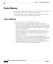
... router. If the power is lost or the router is stored on the Cisco 1700 router is turned off, this guide. The Cisco 1700 router stores a working storage and contains the dynamic configuration information. The Flash memory on mini-Flash modules. The Flash memory structure can load a new level of the operating system in every router in...
... router. If the power is lost or the router is stored on the Cisco 1700 router is turned off, this guide. The Cisco 1700 router stores a working storage and contains the dynamic configuration information. The Flash memory on mini-Flash modules. The Flash memory structure can load a new level of the operating system in every router in...
Hardware Installation Guide
Page 29
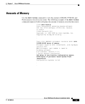
...32 Bridging software. Processor board ID 0000 (1314672220), with 12288K/4096K bytes of memory. Chapter 1 Cisco 1700 Router Overview Amounts of Memory Use the show version command to view the amount of DRAM, NVRAM, and Flash memory stored in this router. 1700# show version command output in bold text displays... the amount of memory stored in your router. Compiled Tue 26-May-98 19:58 by cisco Systems, Inc. X.25 software, Version 3.0.0. 1 Serial ...
...32 Bridging software. Processor board ID 0000 (1314672220), with 12288K/4096K bytes of memory. Chapter 1 Cisco 1700 Router Overview Amounts of Memory Use the show version command to view the amount of DRAM, NVRAM, and Flash memory stored in this router. 1700# show version command output in bold text displays... the amount of memory stored in your router. Compiled Tue 26-May-98 19:58 by cisco Systems, Inc. X.25 software, Version 3.0.0. 1 Serial ...

Hardware Installation Guide
Page 51
...-BNOR2SY56I-M), Experimental Version 12.0(19980725:020859) [aiyagari-devtest_0724 100] Copyright (c) 1986-1998 by power-on Running default software cisco 1720 (MPC860) processor (revision 0x00) with hardware revision 0000 M860 processor: part number 0, mask 32 Bridging software. ...(sync/async) network interface(s) 32K bytes of non-volatile configuration memory. 4096K bytes of processor board System flash (Read/Write) Configuration register is usually 0x2102 or 0x102. It is 0x0 Step 5 Step 6 Record the setting of memory. Cisco 1700 Router Hardware Installation Guide 3-3
...-BNOR2SY56I-M), Experimental Version 12.0(19980725:020859) [aiyagari-devtest_0724 100] Copyright (c) 1986-1998 by power-on Running default software cisco 1720 (MPC860) processor (revision 0x00) with hardware revision 0000 M860 processor: part number 0, mask 32 Bridging software. ...(sync/async) network interface(s) 32K bytes of non-volatile configuration memory. 4096K bytes of processor board System flash (Read/Write) Configuration register is usually 0x2102 or 0x102. It is 0x0 Step 5 Step 6 Record the setting of memory. Cisco 1700 Router Hardware Installation Guide 3-3
Hardware Installation Guide
Page 52
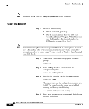
To send a break in Flash memory, and displays the following : • If break is enabled, go to Step 3. Enter no in response to the prompts until the following prompt: rommon 2> Enter ... Router Step 1 Do one of the following : --- Within 60 seconds, press the Break key. System Configuration Dialog --- Go to Step 2. • If break is displayed: Cisco 1700 Router Hardware Installation Guide 3-4 78-5405-03 The terminal displays the ROM monitor prompt. If your keyboard does not have a key labeled Break.
To send a break in Flash memory, and displays the following : • If break is enabled, go to Step 3. Enter no in response to the prompts until the following prompt: rommon 2> Enter ... Router Step 1 Do one of the following : --- Within 60 seconds, press the Break key. System Configuration Dialog --- Go to Step 2. • If break is displayed: Cisco 1700 Router Hardware Installation Guide 3-4 78-5405-03 The terminal displays the ROM monitor prompt. If your keyboard does not have a key labeled Break.
Hardware Installation Guide
Page 67
Do not directly touch the backplane with your Cisco 1700 router and includes the following sections: • Opening the Chassis • Locating Memory • Installing a Mini-Flash Module • Installing a DIMM • Closing the Chassis Warning During this procedure, wear grounding wrist straps to avoid ESD damage to install or upgrade memory in your hand or any metal tool, or you could shock yourself. 78-5405-03 Cisco 1700 Router Hardware Installation Guide C-1 APPENDIX C Installing and Upgrading Router Memory This chapter describes how to the router.
Do not directly touch the backplane with your Cisco 1700 router and includes the following sections: • Opening the Chassis • Locating Memory • Installing a Mini-Flash Module • Installing a DIMM • Closing the Chassis Warning During this procedure, wear grounding wrist straps to avoid ESD damage to install or upgrade memory in your hand or any metal tool, or you could shock yourself. 78-5405-03 Cisco 1700 Router Hardware Installation Guide C-1 APPENDIX C Installing and Upgrading Router Memory This chapter describes how to the router.
Hardware Installation Guide
Page 70
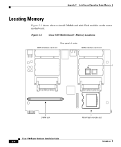
Appendix C Installing and Upgrading Router Memory Locating Memory Figure C-2 shows where to install DIMMs and mini-Flash modules on the router motherboard. Figure C-2 Cisco 1700 Motherboard-Memory Locations Rear panel of router WAN interface card slot WAN interface card slot B 12610 DIMM slot Cisco 1700 Router Hardware Installation Guide C-4 Mini-Flash module slot 78-5405-03
Appendix C Installing and Upgrading Router Memory Locating Memory Figure C-2 shows where to install DIMMs and mini-Flash modules on the router motherboard. Figure C-2 Cisco 1700 Motherboard-Memory Locations Rear panel of router WAN interface card slot WAN interface card slot B 12610 DIMM slot Cisco 1700 Router Hardware Installation Guide C-4 Mini-Flash module slot 78-5405-03
Hardware Installation Guide
Page 71
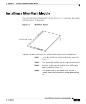
... hear a clicking sound and the module is firmly inserted in the slot. 78-5405-03 Cisco 1700 Router Hardware Installation Guide C-5 Figure C-3 Mini-Flash Module Notched edge 12612 Take the following steps to increase the amount of Flash memory in the router. Step 3 Insert the module into the module slot at a 45-degree angle...
... hear a clicking sound and the module is firmly inserted in the slot. 78-5405-03 Cisco 1700 Router Hardware Installation Guide C-5 Figure C-3 Mini-Flash Module Notched edge 12612 Take the following steps to increase the amount of Flash memory in the router. Step 3 Insert the module into the module slot at a 45-degree angle...
Hardware Installation Guide
Page 72
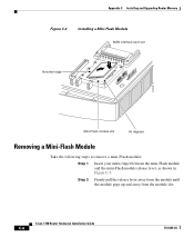
Appendix C Installing and Upgrading Router Memory Figure C-4 Installing a Mini-Flash Module WAN interface card slot Notched edge 12613 Mini-Flash module slot 45 degrees Removing a Mini-Flash Module Take the following steps to remove a mini-Flash module: Step 1 Insert your index finger between the mini-Flash module and the mini-Flash module release lever, as shown in Figure C-5. Cisco 1700 Router Hardware Installation Guide C-6 78-5405-03 Step 2 Firmly pull the release lever away from the module until the module pops up and away from the module slot.
Appendix C Installing and Upgrading Router Memory Figure C-4 Installing a Mini-Flash Module WAN interface card slot Notched edge 12613 Mini-Flash module slot 45 degrees Removing a Mini-Flash Module Take the following steps to remove a mini-Flash module: Step 1 Insert your index finger between the mini-Flash module and the mini-Flash module release lever, as shown in Figure C-5. Cisco 1700 Router Hardware Installation Guide C-6 78-5405-03 Step 2 Firmly pull the release lever away from the module until the module pops up and away from the module slot.

Hardware Installation Guide
Page 73
... to increase the amount of the DIMM are inserted over the bars inside the DIMM slot, as in Figure C-6. 78-5405-03 Cisco 1700 Router Hardware Installation Guide C-7 Step 1 Locate the DIMM slot on the router motherboard. Step 2 Remove any existing DIMM by ... sure that the notches on the edge of dynamic random-access memory (DRAM) in the router. Appendix C Installing and Upgrading Router Memory Figure C-5 Removing a Mini-Flash Module 12614 Mini-Flash module release lever Installing a DIMM You can install a dual inline memory module (DIMM) to install a DIMM on the motherboard, shown...
... to increase the amount of the DIMM are inserted over the bars inside the DIMM slot, as in Figure C-6. 78-5405-03 Cisco 1700 Router Hardware Installation Guide C-7 Step 1 Locate the DIMM slot on the router motherboard. Step 2 Remove any existing DIMM by ... sure that the notches on the edge of dynamic random-access memory (DRAM) in the router. Appendix C Installing and Upgrading Router Memory Figure C-5 Removing a Mini-Flash Module 12614 Mini-Flash module release lever Installing a DIMM You can install a dual inline memory module (DIMM) to install a DIMM on the motherboard, shown...
Hardware Installation Guide
Page 85
...on router C-4 front panel illustration 1-2 LEDs description 1-6 to 1-7 illustration 1-6 H hub connecting to 2-3 description 1-10 I installing DIMM C-7 equipment you provide 1-10 Flash memory C-5 preparing for 2-1 verifying using LEDs 2-4, 2-10 wall-mounting 2-4 78-5405-03 Index WAN interface cards 2-4 Integrated Services Digital Network See ISDN BRI ISDN See...D-2 point-to-point service D-2 provisioning D-3 to D-4 SPID configuring D-4 definition D-4 switch types D-2 isdn spid command D-5 isdn switch-type command D-2 K Kensington-compatible 1-3 Cisco 1700 Router Hardware Installation Guide IN-3
...on router C-4 front panel illustration 1-2 LEDs description 1-6 to 1-7 illustration 1-6 H hub connecting to 2-3 description 1-10 I installing DIMM C-7 equipment you provide 1-10 Flash memory C-5 preparing for 2-1 verifying using LEDs 2-4, 2-10 wall-mounting 2-4 78-5405-03 Index WAN interface cards 2-4 Integrated Services Digital Network See ISDN BRI ISDN See...D-2 point-to-point service D-2 provisioning D-3 to D-4 SPID configuring D-4 definition D-4 switch types D-2 isdn spid command D-5 isdn switch-type command D-2 K Kensington-compatible 1-3 Cisco 1700 Router Hardware Installation Guide IN-3

Hardware Installation Guide
Page 86
... 1-6 to 1-7 illustration 1-6 OK LED diagnostics 3-7 rear panel description 1-4 illustration 1-4 using to verify installation 2-10 M memory description 1-8 DIMM installing C-7 locating on router C-4 displaying amounts 1-9 DRAM description 1-8 Flash description 1-8 installing C-5 locating on router C-4 NVRAM description 1-8 show version command 1-9 modem connecting to router 2-12 description ...11 connecting to router 2-11 terminal emulation settings 2-11 pinouts console cable B-3 Ethernet cable B-2 power, troubleshooting 3-9 IN-4 Cisco 1700 Router Hardware Installation Guide 78-5405-03
... 1-6 to 1-7 illustration 1-6 OK LED diagnostics 3-7 rear panel description 1-4 illustration 1-4 using to verify installation 2-10 M memory description 1-8 DIMM installing C-7 locating on router C-4 displaying amounts 1-9 DRAM description 1-8 Flash description 1-8 installing C-5 locating on router C-4 NVRAM description 1-8 show version command 1-9 modem connecting to router 2-12 description ...11 connecting to router 2-11 terminal emulation settings 2-11 pinouts console cable B-3 Ethernet cable B-2 power, troubleshooting 3-9 IN-4 Cisco 1700 Router Hardware Installation Guide 78-5405-03

