
User Guide
Page 6
The ports will be supported in the drive. Cisco 2811 and Cisco 2821 Integrated Services Router FIPS 140-2 Non Proprietary Security Policy 6 OL-8663-01 Cisco 2811 and Cisco 2821 Routers Table 4 Cisco 2811 FIPS 140-2 Logical Interfaces Router Physical Interface 10/100 Ethernet LAN Ports HWIC Ports Console Port Auxiliary... LED Compact Flash LED Console Port Auxiliary Port Main Power Plug Redundant Power Supply Plug FIPS 140-2 Logical Interface Data Input Interface Data Output Interface Control Input Interface Status Output Interface Power Interface There are two USB ports but they are not...
The ports will be supported in the drive. Cisco 2811 and Cisco 2821 Integrated Services Router FIPS 140-2 Non Proprietary Security Policy 6 OL-8663-01 Cisco 2811 and Cisco 2821 Routers Table 4 Cisco 2811 FIPS 140-2 Logical Interfaces Router Physical Interface 10/100 Ethernet LAN Ports HWIC Ports Console Port Auxiliary... LED Compact Flash LED Console Port Auxiliary Port Main Power Plug Redundant Power Supply Plug FIPS 140-2 Logical Interface Data Input Interface Data Output Interface Control Input Interface Status Output Interface Power Interface There are two USB ports but they are not...
User Guide
Page 11
...Cisco 2821 Routers Table 8 Cisco 2821 FIPS 140-2 Logical Interfaces (Continued) 10/100 Ethernet LAN Port LEDs AIM LEDs PVDM LEDs Power LED Activity LEDs Auxiliary LED Compact Flash LED Console Port Auxiliary Port Main Power Plug Redundant Power Supply Plug Status Output Interface Power Interface There are two USB ports but they are two main roles in Cisco 2811 and Cisco 2821... is correct, the User is considered an internal memory module. OL-8663-01 Cisco 2811 and Cisco 2821 Integrated Services Router FIPS 140-2 Non Proprietary Security Policy 11 Tamper evident seal will be supported in...
...Cisco 2821 Routers Table 8 Cisco 2821 FIPS 140-2 Logical Interfaces (Continued) 10/100 Ethernet LAN Port LEDs AIM LEDs PVDM LEDs Power LED Activity LEDs Auxiliary LED Compact Flash LED Console Port Auxiliary Port Main Power Plug Redundant Power Supply Plug Status Output Interface Power Interface There are two USB ports but they are two main roles in Cisco 2811 and Cisco 2821... is correct, the User is considered an internal memory module. OL-8663-01 Cisco 2811 and Cisco 2821 Integrated Services Router FIPS 140-2 Non Proprietary Security Policy 11 Tamper evident seal will be supported in...

Quick Start Guide
Page 3
... ports. and 36 ports of IP phone power output. • In Cisco 2821 routers, the network module slot adds support for reference: Company product purchased from Company telephone number Product model number Product serial number Maintenance contract number 2 Overview The Cisco 2800 series integrated services routers include the Cisco 2801, Cisco 2811, Cisco 2821, and Cisco 2851 routers. The EVM slot supports additional voice...
... ports. and 36 ports of IP phone power output. • In Cisco 2821 routers, the network module slot adds support for reference: Company product purchased from Company telephone number Product model number Product serial number Maintenance contract number 2 Overview The Cisco 2800 series integrated services routers include the Cisco 2801, Cisco 2811, Cisco 2821, and Cisco 2851 routers. The EVM slot supports additional voice...
Quick Start Guide
Page 12
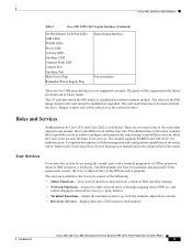
...on the front. To comply with modules and interface cards. Statement 1 You can also be hazardous. Installing the Router Note Cisco 2800 series routers are not designed to a general-purpose outlet could be mounted on a wall or other flat surface. Incorrectly ... Cisco 2800 series hardware installation documentation at the AC power service equipment (see the data sheet for electromagnetic compatibility and safety, an external Surge Protective Device (SPD) is open, or both. The telecommunications lines must be installed and maintained by service personnel as power supplies,...
...on the front. To comply with modules and interface cards. Statement 1 You can also be hazardous. Installing the Router Note Cisco 2800 series routers are not designed to a general-purpose outlet could be mounted on a wall or other flat surface. Incorrectly ... Cisco 2800 series hardware installation documentation at the AC power service equipment (see the data sheet for electromagnetic compatibility and safety, an external Surge Protective Device (SPD) is open, or both. The telecommunications lines must be installed and maintained by service personnel as power supplies,...
Quick Start Guide
Page 21
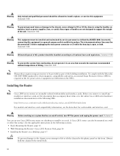
...DC Wiring Requirements for the power connections. A Cisco 2800 series integrated services router with national and local wiring regulations. Install only in this section for proper wiring. Statement 1025 Note The DC-input power supply does not apply to DC power. Both sources must be ...circuit (overcurrent) protection. If backup power is required, see the "Connecting the Router to DC Power If your router has a DC-input power supply, follow the directions in accordance with a DC-input power supply requires copper wire for Cisco 2821 and Cisco 2851 Routers DC Input 24-36 VDC, ...
...DC Wiring Requirements for the power connections. A Cisco 2800 series integrated services router with national and local wiring regulations. Install only in this section for proper wiring. Statement 1025 Note The DC-input power supply does not apply to DC power. Both sources must be ...circuit (overcurrent) protection. If backup power is required, see the "Connecting the Router to DC Power If your router has a DC-input power supply, follow the directions in accordance with a DC-input power supply requires copper wire for Cisco 2821 and Cisco 2851 Routers DC Input 24-36 VDC, ...

Quick Start Guide
Page 22
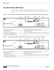
... wire. Wire the DC power supply as shown in the OFF position. Statement 239 Warning An exposed wire lead from the DC circuit. Wiring Procedure for DC Input To connect the router to a DC power source, perform the following procedures, ensure that power is ground to ground, ...the following steps: Step 1 Remove power from a DC-input power source can conduct harmful levels of the DC-input power source wire extends from the terminal block. Connect each wire to the terminal block, starting with upturned lugs. Save the covers for Cisco 2800 Series Routers (Typical) -DC, input A...
... wire. Wire the DC power supply as shown in the OFF position. Statement 239 Warning An exposed wire lead from the DC circuit. Wiring Procedure for DC Input To connect the router to a DC power source, perform the following procedures, ensure that power is ground to ground, ...the following steps: Step 1 Remove power from a DC-input power source can conduct harmful levels of the DC-input power source wire extends from the terminal block. Connect each wire to the terminal block, starting with upturned lugs. Save the covers for Cisco 2800 Series Routers (Typical) -DC, input A...

Quick Start Guide
Page 24
... This is allowed only if Va equals Vb (within 0.25 volts). fuses to open, resulting in lack of the dual input DC power supply's internal A- Both sources must be the same polarity (with common positive terminals, if source A and source B voltages are within 0.25...A input or the B input. Approved Scenarios and Scenarios Not Approved for Dual DC Power Supply Configuration You can cause one source to the B input. Figure 21 Connecting to Cisco 2811, Cisco 2821, and Cisco 2851 series integrated services routers. or B- Do not connect -DC grounded and +DC grounded dual sources to One...
... This is allowed only if Va equals Vb (within 0.25 volts). fuses to open, resulting in lack of the dual input DC power supply's internal A- Both sources must be the same polarity (with common positive terminals, if source A and source B voltages are within 0.25...A input or the B input. Approved Scenarios and Scenarios Not Approved for Dual DC Power Supply Configuration You can cause one source to the B input. Figure 21 Connecting to Cisco 2811, Cisco 2821, and Cisco 2851 series integrated services routers. or B- Do not connect -DC grounded and +DC grounded dual sources to One...
User Guide
Page 3
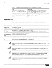
...for example passwords, appear in angle brackets in contexts where italics are located internally within the router, such as memory modules, AIMs, PVDMs, and power supplies. Note Means reader take note. Conventions These documents use the conventions listed in Table 2 to... the paragraph. Conventions Table 1 Hardware Documentation for Cisco 2800 Series Routers (Continued) Topic Installing and Upgrading Internal Modules in Cisco 2800 Series Routers Removing and Installing CompactFlash Memory Cards in Cisco 2800 Series Routers Description Describes how to system prompts appear in square...
...for example passwords, appear in angle brackets in contexts where italics are located internally within the router, such as memory modules, AIMs, PVDMs, and power supplies. Note Means reader take note. Conventions These documents use the conventions listed in Table 2 to... the paragraph. Conventions Table 1 Hardware Documentation for Cisco 2800 Series Routers (Continued) Topic Installing and Upgrading Internal Modules in Cisco 2800 Series Routers Removing and Installing CompactFlash Memory Cards in Cisco 2800 Series Routers Description Describes how to system prompts appear in square...
User Guide
Page 21
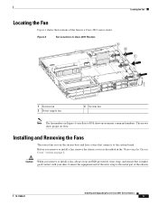
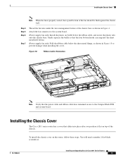
The arrows show environment command numbers. Installing and Removing the Fans The router fans rest on page 2. Caution When you remove or install a fan, remove the chassis cover...Connect the equipment end of the wrist strap to the metal part of the fans in a Cisco 2811 series router. Figure 4 Fan Locations in Cisco 2811 Routers 3 2 1 271118 1 System fan 3 Power supply fan 2 System fan Note The fan numbers in Figure 4 correllate to the system board. Before... 4 shows the locations of the chassis. 78-17850-01 Installing and Upgrading Fans in Cisco 2811 Series Routers 5
The arrows show environment command numbers. Installing and Removing the Fans The router fans rest on page 2. Caution When you remove or install a fan, remove the chassis cover...Connect the equipment end of the wrist strap to the metal part of the fans in a Cisco 2811 series router. Figure 4 Fan Locations in Cisco 2811 Routers 3 2 1 271118 1 System fan 3 Power supply fan 2 System fan Note The fan numbers in Figure 4 correllate to the system board. Before... 4 shows the locations of the chassis. 78-17850-01 Installing and Upgrading Fans in Cisco 2811 Series Routers 5
User Guide
Page 24
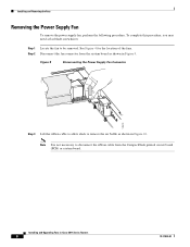
... complete this procedure, you may need a flat-blade screwdriver. Step 1 Locate the fan to remove the air baffle as shown in Cisco 2811 Series Routers 8 78-17850-01 Figure 9 Disconnecting the Power Supply Fan Connector 170510 Step 3 Lift the ribbon cable to allow slack to be removed. See Figure 4 for the location of the... fan connector from the CompactFlash printed circuit board (PCB) or system board. Installing and Upgrading Fans in Figure 9. Installing and Removing the Fans Removing the Power Supply Fan To remove the power supply fan, perform the following procedure.
... complete this procedure, you may need a flat-blade screwdriver. Step 1 Locate the fan to remove the air baffle as shown in Cisco 2811 Series Routers 8 78-17850-01 Figure 9 Disconnecting the Power Supply Fan Connector 170510 Step 3 Lift the ribbon cable to allow slack to be removed. See Figure 4 for the location of the... fan connector from the CompactFlash printed circuit board (PCB) or system board. Installing and Upgrading Fans in Figure 9. Installing and Removing the Fans Removing the Power Supply Fan To remove the power supply fan, perform the following procedure.
User Guide
Page 27
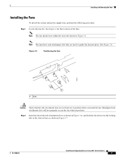
... Fan 170515 1 1 Tabs Caution Verify that are not bent out of the fans. Note The fan should seat within the four tabs shown in Cisco 2811 Series Routers 11 See Figure 4 for the location of position when you instal the fan. Note The fans have side attachment slots that the side attachment... side attachment slots will not properly secure the fan when in position. Installing and Removing the Fans Installing the Fans To install the system and power supply fans, perform the following procedure: Step 1 Locate the fan slot.
... Fan 170515 1 1 Tabs Caution Verify that are not bent out of the fans. Note The fan should seat within the four tabs shown in Cisco 2811 Series Routers 11 See Figure 4 for the location of position when you instal the fan. Note The fans have side attachment slots that the side attachment... side attachment slots will not properly secure the fan when in position. Installing and Removing the Fans Installing the Fans To install the system and power supply fans, perform the following procedure: Step 1 Locate the fan slot.
User Guide
Page 29
...Install the plastic air baffle below the sheet metal flange, as shown in Cisco 2811 Series Routers 13 Installing the Chassis Cover The Cisco 2811 series router has a cover that slides into the sheet metal hold-downs. (Power supply fan only) Fold the ribbon cable below the ribbon cable, and secure .... Figure 18 Ribbon Cable Orientation 170546 Note Verify that the four bottom hooks can snap into place after you position it flat on the router, follow these steps. You will need a number 2 flat-blade screwdriver. 78-17850-01 Installing and Upgrading Fans in Figure 6. Installing ...
...Install the plastic air baffle below the sheet metal flange, as shown in Cisco 2811 Series Routers 13 Installing the Chassis Cover The Cisco 2811 series router has a cover that slides into the sheet metal hold-downs. (Power supply fan only) Fold the ribbon cable below the ribbon cable, and secure .... Figure 18 Ribbon Cable Orientation 170546 Note Verify that the four bottom hooks can snap into place after you position it flat on the router, follow these steps. You will need a number 2 flat-blade screwdriver. 78-17850-01 Installing and Upgrading Fans in Figure 6. Installing ...
User Guide
Page 37
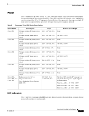
... chassis power supply is installed. With Cisco 2811: -48 VDC, 160 W With Cisco 2821: -48 VDC, 240 W With Cisco 2851: -48 VDC, 360 W LED Indicators Table 5 and Table 6 summarize the LED indicators that are equipped for operation using either AC or DC input power by installation of Cisco 2800 Series Power Options Router Model Cisco 2801 Cisco 2811 Cisco 2821 Cisco 2851 Cisco 2811, Cisco 2821, and Cisco 2851 Power...
... chassis power supply is installed. With Cisco 2811: -48 VDC, 160 W With Cisco 2821: -48 VDC, 240 W With Cisco 2851: -48 VDC, 360 W LED Indicators Table 5 and Table 6 summarize the LED indicators that are equipped for operation using either AC or DC input power by installation of Cisco 2800 Series Power Options Router Model Cisco 2801 Cisco 2811 Cisco 2821 Cisco 2851 Cisco 2811, Cisco 2821, and Cisco 2851 Power...
User Guide
Page 38
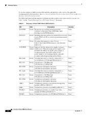
... the software is functional. This LED blinks while booting or in the "Troubleshooting Cisco 2800 Series Routers" document. When the inline power supply is not installed, the LED is on). If the power supply is not working properly, the LED is green. Front Green On indicates presence ...Mbps link. Front Green On indicates full-duplex operation. Front Green On indicates presence of an advanced integration module (AIM) in PVDM slot 1. Front Green On when the router is correctly connected to a local Ethernet LAN through Ethernet port 1. Off indicates a 10-Mbps link....
... the software is functional. This LED blinks while booting or in the "Troubleshooting Cisco 2800 Series Routers" document. When the inline power supply is not installed, the LED is on). If the power supply is not working properly, the LED is green. Front Green On indicates presence ...Mbps link. Front Green On indicates full-duplex operation. Front Green On indicates presence of an advanced integration module (AIM) in PVDM slot 1. Front Green On when the router is correctly connected to a local Ethernet LAN through Ethernet port 1. Off indicates a 10-Mbps link....
User Guide
Page 40
... with the inline power supply, for the router, and is not installed in ambient temperatures above 32oC. The Cisco 2811 router has three fans that operate at a slower speed to verify the validity of router air intake and exhaust...servicing. Caution Your chassis installation must allow unrestricted airflow for the router. They operate at high speed in ambient temperatures above 25 degree C and with ambient temperatures consistently above 40oC. They operate at the highest speed in ambient temperatures above 40oC. In the Cisco 2811, Cisco 2821, and Cisco 2851 routers...
... with the inline power supply, for the router, and is not installed in ambient temperatures above 32oC. The Cisco 2811 router has three fans that operate at a slower speed to verify the validity of router air intake and exhaust...servicing. Caution Your chassis installation must allow unrestricted airflow for the router. They operate at high speed in ambient temperatures above 25 degree C and with ambient temperatures consistently above 40oC. They operate at the highest speed in ambient temperatures above 40oC. In the Cisco 2811, Cisco 2821, and Cisco 2851 routers...
User Guide
Page 42
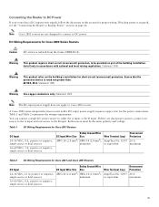
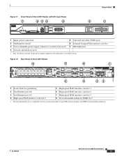
... switch 6 External CompactFlash memory card slot 3 Cisco redundant power supply connector (covered if not used) 7 LED indicators 4 Console and auxiliary ports Overview of a Cisco 2811 router. Figure 12 shows the rear panel of Cisco 2800 Series Routers 12 OL-5783-01 Chassis Views Figure 8 3 Back Panel of the Cisco 2801 Router 2 1 95905 95551 1 Input power connector 2 On/Off switch 3 Chassis...
... switch 6 External CompactFlash memory card slot 3 Cisco redundant power supply connector (covered if not used) 7 LED indicators 4 Console and auxiliary ports Overview of a Cisco 2811 router. Figure 12 shows the rear panel of Cisco 2800 Series Routers 12 OL-5783-01 Chassis Views Figure 8 3 Back Panel of the Cisco 2801 Router 2 1 95905 95551 1 Input power connector 2 On/Off switch 3 Chassis...
User Guide
Page 43
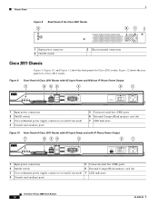
... 5 Universal serial bus (USB) ports 6 External CompactFlash memory card slot 3 Cisco redundant power supply connector (covered if not used) 7 LED indicators 4 Console and auxiliary ports 1. Figure 12 Rear Panel of Cisco 2800 Series Routers 13 95552 Chassis Views Figure 11 Front Panel of Cisco 2811 Router with Cisco network modules of type NM (network module) and NME (network...
... 5 Universal serial bus (USB) ports 6 External CompactFlash memory card slot 3 Cisco redundant power supply connector (covered if not used) 7 LED indicators 4 Console and auxiliary ports 1. Figure 12 Rear Panel of Cisco 2800 Series Routers 13 95552 Chassis Views Figure 11 Front Panel of Cisco 2811 Router with Cisco network modules of type NM (network module) and NME (network...
User Guide
Page 44
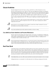
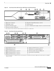
... 3 Console and auxiliary ports 4 Universal serial bus (USB) ports 5 External CompactFlash memory card slot 6 LED indicators 7 Cisco redundant power supply connector (covered if not used) Figure 14 Front Panel of Cisco 2821 and Cisco 2851 Routers with AC Input Power and IP Phone Power Output 7 6 5 43 2 1 OPTIONAL RPS INPUT 12V 18A -48V 8A SYS AUX/ SYS 1 PWR PWR ACT...
... 3 Console and auxiliary ports 4 Universal serial bus (USB) ports 5 External CompactFlash memory card slot 6 LED indicators 7 Cisco redundant power supply connector (covered if not used) Figure 14 Front Panel of Cisco 2821 and Cisco 2851 Routers with AC Input Power and IP Phone Power Output 7 6 5 43 2 1 OPTIONAL RPS INPUT 12V 18A -48V 8A SYS AUX/ SYS 1 PWR PWR ACT...
User Guide
Page 45
... 3 Console and auxiliary ports 4 Universal serial bus (USB) ports 5 External CompactFlash memory card slot 6 LED indicators 7 Cisco redundant power supply connector (covered if not used) 1. 95555 Chassis Views Figure 15 Front Panel of Cisco 2821 and Cisco 2851 Routers with Cisco network modules of type NM (network module), NME (network module enhanced), and NME-X (enhanced extended). 95572 OL...
... 3 Console and auxiliary ports 4 Universal serial bus (USB) ports 5 External CompactFlash memory card slot 6 LED indicators 7 Cisco redundant power supply connector (covered if not used) 1. 95555 Chassis Views Figure 15 Front Panel of Cisco 2821 and Cisco 2851 Routers with Cisco network modules of type NM (network module), NME (network module enhanced), and NME-X (enhanced extended). 95572 OL...
User Guide
Page 48
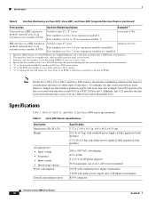
Specifications Table 8 Interface Numbering on Cisco 2811, Cisco 2821, and Cisco 2851 Integrated Services Routers (continued) Port Location Interface Numbering Scheme Examples1, 2 Voice port in a BRI expansion module (internal slot) in an extension voice....9 lb (4.9 kg) with standard power supply if fully populated with modules 13.71 lb (6.2 kg) with inline power supply if fully populated with modules 100 to 240 VAC, autoranging 47 to specify the async line. Table 9 Cisco 2801 Router Specifications Description Dimensions (H x W x D) Weight AC input power • Input voltage • ...
Specifications Table 8 Interface Numbering on Cisco 2811, Cisco 2821, and Cisco 2851 Integrated Services Routers (continued) Port Location Interface Numbering Scheme Examples1, 2 Voice port in a BRI expansion module (internal slot) in an extension voice....9 lb (4.9 kg) with standard power supply if fully populated with modules 13.71 lb (6.2 kg) with inline power supply if fully populated with modules 100 to 240 VAC, autoranging 47 to specify the async line. Table 9 Cisco 2801 Router Specifications Description Dimensions (H x W x D) Weight AC input power • Input voltage • ...


