Hardware Installation Guide
Page 6
...12 RPS LED 1-13 Port LEDs and Modes 1-14 Module Slot LEDs 1-19 Rear-Panel Description 1-19 Power Connectors 1-21 Internal Power Supply Connector 1-21 DC Power Connector 1-21 Cisco... RPS Connector 1-22 Console Port 1-23 2 C H A P T E R Installation 2-1 Preparing for Installation 2-1 Warnings 2-1 EMC Regulatory Statements 2-4 U.S.A. 2-4 Taiwan 2-4 Japan 2-5 Korea 2-5 Hungary 2-6 Installation Guidelines 2-6 Verifying Package Contents 2-7 Installing the Switch on a Table or Shelf 2-9 Installing the Switch in a Rack 2-9 Removing Screws from the Switch 2-11 Attaching the Brackets to a Catalyst...
...12 RPS LED 1-13 Port LEDs and Modes 1-14 Module Slot LEDs 1-19 Rear-Panel Description 1-19 Power Connectors 1-21 Internal Power Supply Connector 1-21 DC Power Connector 1-21 Cisco... RPS Connector 1-22 Console Port 1-23 2 C H A P T E R Installation 2-1 Preparing for Installation 2-1 Warnings 2-1 EMC Regulatory Statements 2-4 U.S.A. 2-4 Taiwan 2-4 Japan 2-5 Korea 2-5 Hungary 2-6 Installation Guidelines 2-6 Verifying Package Contents 2-7 Installing the Switch on a Table or Shelf 2-9 Installing the Switch in a Rack 2-9 Removing Screws from the Switch 2-11 Attaching the Brackets to a Catalyst...

Hardware Installation Guide
Page 7
...18 Attaching the Optional Cable Guide 2-19 Installing the Switch on a Wall 2-20 Attaching the Brackets to the Switch 2-21 Mounting the Switch to a Wall 2-22 Powering On the Switch and Running POST 2-24 Connecting to DC Power 2-25 Preparing for Installation 2-25 Grounding the Switch 2-26 Wiring the DC-Input Power Source 2-29... Correcting Module POST Failures 3-2 Diagnosing Problems 3-3 Technical Specifications A-1 Connectors and Cable Specifications B-1 Connector Specifications B-1 10/100 Ports B-1 100BASE-FX Ports B-2 Contents 78-6461-04 Catalyst 2900 Series XL Hardware Installation Guide vii
...18 Attaching the Optional Cable Guide 2-19 Installing the Switch on a Wall 2-20 Attaching the Brackets to the Switch 2-21 Mounting the Switch to a Wall 2-22 Powering On the Switch and Running POST 2-24 Connecting to DC Power 2-25 Preparing for Installation 2-25 Grounding the Switch 2-26 Wiring the DC-Input Power Source 2-29... Correcting Module POST Failures 3-2 Diagnosing Problems 3-3 Technical Specifications A-1 Connectors and Cable Specifications B-1 Connector Specifications B-1 10/100 Ports B-1 100BASE-FX Ports B-2 Contents 78-6461-04 Catalyst 2900 Series XL Hardware Installation Guide vii
Hardware Installation Guide
Page 9
INDEX Class 1 Laser Product Warning C-22 Laser Beam Exposure Warning C-23 No On/Off Switch Warning C-24 Chassis Warning-Rack-Mounting and Servicing C-25 Reinforced Insulation Warning C-29 LAN Connections Only Warning C-30 No Field-Replaceable Units Warning C-31 Installation ... Equipment Warning C-36 Ground Connection Warning C-37 Qualified Personnel Warning C-38 DC Power Disconnection Warning C-39 Exposed Wire Lead Warning C-41 Contents 78-6461-04 Catalyst 2900 Series XL Hardware Installation Guide ix
INDEX Class 1 Laser Product Warning C-22 Laser Beam Exposure Warning C-23 No On/Off Switch Warning C-24 Chassis Warning-Rack-Mounting and Servicing C-25 Reinforced Insulation Warning C-29 LAN Connections Only Warning C-30 No Field-Replaceable Units Warning C-31 Installation ... Equipment Warning C-36 Ground Connection Warning C-37 Qualified Personnel Warning C-38 DC Power Disconnection Warning C-39 Exposed Wire Lead Warning C-41 Contents 78-6461-04 Catalyst 2900 Series XL Hardware Installation Guide ix
Hardware Installation Guide
Page 11
... a wall. Chapter 2, "Installation," provides the procedures for installing and configuring a Catalyst 2900 series XL switch. It describes the physical and performance characteristics of Catalyst 2900 series XL switches. Preface Audience This guide is organized into the following chapters: Chapter 1, "Product Overview," summarizes the switch features and describes the ports, the standards they support, and the...
... a wall. Chapter 2, "Installation," provides the procedures for installing and configuring a Catalyst 2900 series XL switch. It describes the physical and performance characteristics of Catalyst 2900 series XL switches. Preface Audience This guide is organized into the following chapters: Chapter 1, "Product Overview," summarizes the switch features and describes the ports, the standards they support, and the...
Hardware Installation Guide
Page 12
... translations in various languages of data. Notes, cautions, and warnings use these conventions: • Commands and keywords are in italic. Catalyst 2900 Series XL Hardware Installation Guide xii 78-6461-04 Conventions This guide uses the following conventions and symbols: Note Means reader take ... in boldface screen font. • Nonprinting characters, such as passwords or tabs, are in boldface. • Arguments for the switches and the regulatory agency approvals. Caution Means reader be used to connect to materials not contained in this situation, you supply values are...
... translations in various languages of data. Notes, cautions, and warnings use these conventions: • Commands and keywords are in italic. Catalyst 2900 Series XL Hardware Installation Guide xii 78-6461-04 Conventions This guide uses the following conventions and symbols: Note Means reader take ... in boldface screen font. • Nonprinting characters, such as passwords or tabs, are in boldface. • Arguments for the switches and the regulatory agency approvals. Caution Means reader be used to connect to materials not contained in this situation, you supply values are...

Hardware Installation Guide
Page 15
... sites and from the telephone numbers listed in the "Obtaining Documentation" section on page xvi. • Release Notes for the Catalyst 2900 Series XL and Catalyst 3500 Series XL Switches (not orderable but is available on Cisco.com) Note Switch requirements and procedures for initial configurations and software upgrades tend to the release notes on...
... sites and from the telephone numbers listed in the "Obtaining Documentation" section on page xvi. • Release Notes for the Catalyst 2900 Series XL and Catalyst 3500 Series XL Switches (not orderable but is available on Cisco.com) Note Switch requirements and procedures for initial configurations and software upgrades tend to the release notes on...
Hardware Installation Guide
Page 16
... online help (available only from the switch CMS software) • Catalyst 2900 Series XL Hardware Installation Guide (order number DOC-786461=) • Catalyst 3500 Series XL Hardware Installation Guide (order number DOC-786456=) • Catalyst 2900 Series XL Modules Installation Guide (order...1000BASE-T Gigabit Interface Converter Installation Note (not orderable but is available on Cisco.com) • Catalyst GigaStack Gigabit Interface Converter Hardware Installation Guide (order number DOC-786460=) • Cisco LRE CPE Hardware Installation Guide (order number DOC-7811469=) • ...
... online help (available only from the switch CMS software) • Catalyst 2900 Series XL Hardware Installation Guide (order number DOC-786461=) • Catalyst 3500 Series XL Hardware Installation Guide (order number DOC-786456=) • Catalyst 2900 Series XL Modules Installation Guide (order...1000BASE-T Gigabit Interface Converter Installation Note (not orderable but is available on Cisco.com) • Catalyst GigaStack Gigabit Interface Converter Hardware Installation Guide (order number DOC-786460=) • Cisco LRE CPE Hardware Installation Guide (order number DOC-7811469=) • ...
Hardware Installation Guide
Page 21
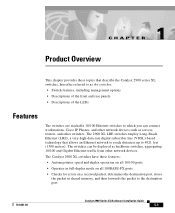
... rear panels • Descriptions of the LEDs Features The switches are stackable 10/100 Ethernet switches to which you can be deployed as servers, routers, and other network devices. The Catalyst 2900 XL switches have these topics that allows an Ethernet network to reach distances... shared memory, and then forwards the packet to the destination port 78-6461-04 Catalyst 2900 Series XL Hardware Installation Guide 1-1 The switches can connect workstations, Cisco IP Phones, and other network devices such as backbone switches, aggregating 10/100 and Gigabit Ethernet traffic from other...
... rear panels • Descriptions of the LEDs Features The switches are stackable 10/100 Ethernet switches to which you can be deployed as servers, routers, and other network devices. The Catalyst 2900 XL switches have these topics that allows an Ethernet network to reach distances... shared memory, and then forwards the packet to the destination port 78-6461-04 Catalyst 2900 Series XL Hardware Installation Guide 1-1 The switches can connect workstations, Cisco IP Phones, and other network devices such as backbone switches, aggregating 10/100 and Gigabit Ethernet traffic from other...
Hardware Installation Guide
Page 22
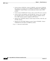
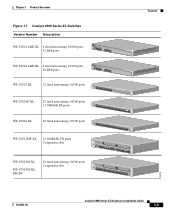
...converter • On the Catalyst 2912 LRE XL and 2924 LRE XL switches, up to 24 LRE ports through one RJ-21 connector and hot swapping capability with the Cisco LRE customer premises equipment (CPE) devices • Supports up to 2048 MAC addresses on the Catalyst 2924 XL, 2924C XL,... and 2912 XL switches • Supports up to 8192 MAC addresses on the Catalyst 2924M XL, Catalyst 2924M XL DC and Catalyst 2912MF XL switches Figure 1-1 shows ...
...converter • On the Catalyst 2912 LRE XL and 2924 LRE XL switches, up to 24 LRE ports through one RJ-21 connector and hot swapping capability with the Cisco LRE customer premises equipment (CPE) devices • Supports up to 2048 MAC addresses on the Catalyst 2924 XL, 2924C XL,... and 2912 XL switches • Supports up to 8192 MAC addresses on the Catalyst 2924M XL, Catalyst 2924M XL DC and Catalyst 2912MF XL switches Figure 1-1 shows ...
Hardware Installation Guide
Page 23
Chapter 1 Product Overview Figure 1-1 Catalyst 2900 Series XL Switches Version Number Description WS-C2912-LRE-XL 4 fixed autosensing 10/100 ports INPUT OUTPUT PWR PWR RESET TEMP FAN 9X 10X 11X 12X 12 LRE ports Cisco RPS 300 WS-C2924-LRE-XL 4 fixed autosensing 10/100 ports 24 LRE ports INPUT OUTPUT PWR PWR RESET... TEMP FAN 9X 10X 11X 12X Cisco RPS 300 WS-C2912-XL 12 fixed autosensing 10/100 ports MODE 1X 2X 3X 4X 5X 6X 7X 8X 9X 10X 10BaseT/100BASE-TX 11X 12X Catalyst 2900 SERIES XL WS-C2924C-XL 22 fixed autosensing 10/100 ports...
Chapter 1 Product Overview Figure 1-1 Catalyst 2900 Series XL Switches Version Number Description WS-C2912-LRE-XL 4 fixed autosensing 10/100 ports INPUT OUTPUT PWR PWR RESET TEMP FAN 9X 10X 11X 12X 12 LRE ports Cisco RPS 300 WS-C2924-LRE-XL 4 fixed autosensing 10/100 ports 24 LRE ports INPUT OUTPUT PWR PWR RESET... TEMP FAN 9X 10X 11X 12X Cisco RPS 300 WS-C2912-XL 12 fixed autosensing 10/100 ports MODE 1X 2X 3X 4X 5X 6X 7X 8X 9X 10X 10BaseT/100BASE-TX 11X 12X Catalyst 2900 SERIES XL WS-C2924C-XL 22 fixed autosensing 10/100 ports...

Hardware Installation Guide
Page 24
... Using CMS, you can fully configure and monitor the switch and switch cluster members from a remote management station. • Simple network management protocol (SNMP)-SNMP provides a means to the Catalyst 2900 Series XL and Catalyst 3500 Series XL Software Configuration Guide. You can fully ...configure and monitor a standalone switch, a specific cluster member, or an entire switch cluster. You can access the CLI either by connecting ...
... Using CMS, you can fully configure and monitor the switch and switch cluster members from a remote management station. • Simple network management protocol (SNMP)-SNMP provides a means to the Catalyst 2900 Series XL and Catalyst 3500 Series XL Software Configuration Guide. You can fully ...configure and monitor a standalone switch, a specific cluster member, or an entire switch cluster. You can access the CLI either by connecting ...
Hardware Installation Guide
Page 26
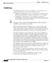
...duplex, 10 Mbps, or 100 Mbps. The 10/100 ports on the Catalyst 3524-PWR XL switch, refer to 328 feet (100 meters) away: • 10BASE-T-compatible devices, such as workstations, Cisco IP Phones, and hubs through standard RJ-45 connectors and Category 3, 4, ...; 100BASE-TX-compatible devices, such as high-speed workstations, Cisco IP Phones, servers, hubs, routers, and other switches through , twisted-pair cable. When connecting the switch to operate in Appendix B, "Connectors and Cable Specifications." Catalyst 2900 Series XL Hardware Installation Guide 1-6 78-6461-04 Unlike...
...duplex, 10 Mbps, or 100 Mbps. The 10/100 ports on the Catalyst 3524-PWR XL switch, refer to 328 feet (100 meters) away: • 10BASE-T-compatible devices, such as workstations, Cisco IP Phones, and hubs through standard RJ-45 connectors and Category 3, 4, ...; 100BASE-TX-compatible devices, such as high-speed workstations, Cisco IP Phones, servers, hubs, routers, and other switches through , twisted-pair cable. When connecting the switch to operate in Appendix B, "Connectors and Cable Specifications." Catalyst 2900 Series XL Hardware Installation Guide 1-6 78-6461-04 Unlike...
Hardware Installation Guide
Page 27
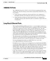
... on the same Catalyst 2900 LRE XL switch, and you can hot swap the CPE devices without powering down the switch or disrupting the other telephone services are configured for each CPE device can reach speeds of up to 15 Mbps (full duplex) and distances of up to 24 Cisco LRE customer premises...100BASE-FX ports use the same cabling as LRE traffic, the LRE port must be connected to the patch panel through a private branch exchange (PBX) switch, a Cisco LRE 48 POTS Splitter can be used. Long-Reach Ethernet Ports The Long-Reach Ethernet (LRE) ports (Figure 1-4) use one RJ-21 connector to ...
... on the same Catalyst 2900 LRE XL switch, and you can hot swap the CPE devices without powering down the switch or disrupting the other telephone services are configured for each CPE device can reach speeds of up to 15 Mbps (full duplex) and distances of up to 24 Cisco LRE customer premises...100BASE-FX ports use the same cabling as LRE traffic, the LRE port must be connected to the patch panel through a private branch exchange (PBX) switch, a Cisco LRE 48 POTS Splitter can be used. Long-Reach Ethernet Ports The Long-Reach Ethernet (LRE) ports (Figure 1-4) use one RJ-21 connector to ...

Hardware Installation Guide
Page 28
...Slots The module slots (see Figure 1-2) are designed to share lines with LRE signals. Due to the proprietary nature of digital PBX switches, some digital PBX switch services use frequencies above 700 kHz do not work when sharing a line with analog, Integrated Services Digital Network (ISDN), and digital...does not have a PBX, a homologated POTS splitter is required to directly connect to the Installation Notes for the Catalyst 2900 XL hot-swappable modules. For more information about the Cisco LRE 48 POTS Splitter (PS-1M-LRE-48), refer to the PSTN. Note If a connection to a ...
...Slots The module slots (see Figure 1-2) are designed to share lines with LRE signals. Due to the proprietary nature of digital PBX switches, some digital PBX switch services use frequencies above 700 kHz do not work when sharing a line with analog, Integrated Services Digital Network (ISDN), and digital...does not have a PBX, a homologated POTS splitter is required to directly connect to the Installation Notes for the Catalyst 2900 XL hot-swappable modules. For more information about the Cisco LRE 48 POTS Splitter (PS-1M-LRE-48), refer to the PSTN. Note If a connection to a ...
Hardware Installation Guide
Page 29
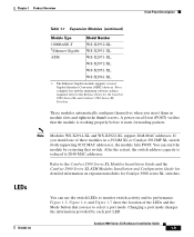
...automatically configure themselves when you insert them in a 2924M XL or Catalyst 2912MF XL switch (both supporting 8192 MAC addresses), the module fails POST. You can use to the Release Notes for Catalyst 2900 series XL switches. Figure 1-5, Figure 1-6, and Figure 1-7 show the location of these...and the minimum software release required, refer to select a port mode. A power-on expansion modules for the Catalyst 2900 Series XL and Catalyst 3500 Series XL Switches. Changing a port mode changes the information provided by restarting that you install one of the LEDs and the ...
...automatically configure themselves when you insert them in a 2924M XL or Catalyst 2912MF XL switch (both supporting 8192 MAC addresses), the module fails POST. You can use to the Release Notes for Catalyst 2900 series XL switches. Figure 1-5, Figure 1-6, and Figure 1-7 show the location of these...and the minimum software release required, refer to select a port mode. A power-on expansion modules for the Catalyst 2900 Series XL and Catalyst 3500 Series XL Switches. Changing a port mode changes the information provided by restarting that you install one of the LEDs and the ...

Hardware Installation Guide
Page 30
... LEDs 10/100 port LEDs System LED Port mode LEDs MODE 1X 2X 3X 4X 5X 6X 7X Mode RPS button LED 47288 1-10 Catalyst 2900 Series XL Hardware Installation Guide 78-6461-04 Front-Panel Description Chapter 1 Product Overview All of the LEDs described in this section except... the utilization meter (UTL) are visible on the Cluster Management Suite (CMS) window and, if the switch is a cluster member, on the CMS Cluster Manager window. The Catalyst 2900 Series XL and Catalyst 3500 Series XL Software Configuration Guide describes how to use CMS to manage standalone or individual...
... LEDs 10/100 port LEDs System LED Port mode LEDs MODE 1X 2X 3X 4X 5X 6X 7X Mode RPS button LED 47288 1-10 Catalyst 2900 Series XL Hardware Installation Guide 78-6461-04 Front-Panel Description Chapter 1 Product Overview All of the LEDs described in this section except... the utilization meter (UTL) are visible on the Cluster Management Suite (CMS) window and, if the switch is a cluster member, on the CMS Cluster Manager window. The Catalyst 2900 Series XL and Catalyst 3500 Series XL Software Configuration Guide describes how to use CMS to manage standalone or individual...
Hardware Installation Guide
Page 32
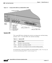
... is not powered up. For information on the System LED colors during POST, see the "Powering On the Switch and Running POST" section on page 2-24. 1-12 Catalyst 2900 Series XL Hardware Installation Guide 78-6461-04 System is receiving power but is receiving power and functioning properly.... Front-Panel Description Figure 1-7 Catalyst 2912 LRE XL and 2924 LRE XL LEDs 10/100 port LEDs Chapter 1 Product...
... is not powered up. For information on the System LED colors during POST, see the "Powering On the Switch and Running POST" section on page 2-24. 1-12 Catalyst 2900 Series XL Hardware Installation Guide 78-6461-04 System is receiving power but is receiving power and functioning properly.... Front-Panel Description Figure 1-7 Catalyst 2912 LRE XL and 2924 LRE XL LEDs 10/100 port LEDs Chapter 1 Product...
Hardware Installation Guide
Page 33
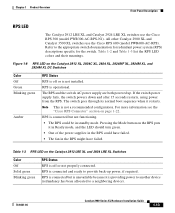
... recommended configuration. RPS is connected but not functioning. • The RPS could have failed. All other Catalyst 2900 XL and Catalyst 3500 XL switches use the Cisco RPS 300 (model PWR300-AC-RPS-N1). RPS is providing power to another device (redundancy has been ...allocated to the appropriate switch documentation for redundant power system (RPS) descriptions specific for the switch. Chapter 1 Product Overview Front-Panel Description RPS LED The Catalyst 2912 LRE XL and Catalyst 2924 LRE XL switches use the Cisco RPS 600 (model PWR600-AC-RPS). ...
... recommended configuration. RPS is connected but not functioning. • The RPS could have failed. All other Catalyst 2900 XL and Catalyst 3500 XL switches use the Cisco RPS 300 (model PWR300-AC-RPS-N1). RPS is providing power to another device (redundancy has been ...allocated to the appropriate switch documentation for redundant power system (RPS) descriptions specific for the switch. Chapter 1 Product Overview Front-Panel Description RPS LED The Catalyst 2912 LRE XL and Catalyst 2924 LRE XL switches use the Cisco RPS 600 (model PWR600-AC-RPS). ...

Hardware Installation Guide
Page 34
...the individual ports. If it does not, the RPS fan could have a port LED. Contact Cisco Systems. The internal power supply in a switch has failed, and the RPS is in standby mode or in use by the switch. (See Figure 1-8.) The port duplex mode: full duplex or half duplex, and default modes:... list the port LED colors. Press the Standby/Active button on the Catalyst 2912 XL, 2924C XL, 2924 XL, 2924MF XL, 2924M XL, and 2924M XL DC Switches Mode LED STAT UTL FDUP 100 Port Mode Port status Switch utilization Port duplex mode Port speed Description The port status. Front-Panel Description...
...the individual ports. If it does not, the RPS fan could have a port LED. Contact Cisco Systems. The internal power supply in a switch has failed, and the RPS is in standby mode or in use by the switch. (See Figure 1-8.) The port duplex mode: full duplex or half duplex, and default modes:... list the port LED colors. Press the Standby/Active button on the Catalyst 2912 XL, 2924C XL, 2924 XL, 2924MF XL, 2924M XL, and 2924M XL DC Switches Mode LED STAT UTL FDUP 100 Port Mode Port status Switch utilization Port duplex mode Port speed Description The port status. Front-Panel Description...

Hardware Installation Guide
Page 35
...Reach Ethernet (LRE) link status of the 10/100 or 100BASE-FX switch ports or the Ethernet link status on the remote CPE. The default setting is active, the 10/100 switch ports on the Catalyst 2912 LRE XL and Catalyst 2924 LRE XL switches. Ethernet link status of the LRE ports on the... Catalyst 2912 LRE XL and Catalyst 2924 LRE XL continue to show Ethernet link status. Default mode on these...
...Reach Ethernet (LRE) link status of the 10/100 or 100BASE-FX switch ports or the Ethernet link status on the remote CPE. The default setting is active, the 10/100 switch ports on the Catalyst 2912 LRE XL and Catalyst 2924 LRE XL switches. Ethernet link status of the LRE ports on the... Catalyst 2912 LRE XL and Catalyst 2924 LRE XL continue to show Ethernet link status. Default mode on these...


