Hardware Installation Guide
Page 6
...12 RPS LED 1-13 Port LEDs and Modes 1-14 Module Slot LEDs 1-19 Rear-Panel Description 1-19 Power Connectors 1-21 Internal Power Supply Connector 1-21 DC Power Connector 1-21 Cisco ...RPS Connector 1-22 Console Port 1-23 2 C H A P T E R Installation 2-1 Preparing for Installation 2-1 Warnings 2-1 EMC Regulatory Statements 2-4 U.S.A. 2-4 Taiwan 2-4 Japan 2-5 Korea 2-5 Hungary 2-6 Installation Guidelines 2-6 Verifying Package Contents 2-7 Installing the Switch on a Table or Shelf 2-9 Installing the Switch in a Rack 2-9 Removing Screws from the Switch 2-11 Attaching the Brackets to a Catalyst...
...12 RPS LED 1-13 Port LEDs and Modes 1-14 Module Slot LEDs 1-19 Rear-Panel Description 1-19 Power Connectors 1-21 Internal Power Supply Connector 1-21 DC Power Connector 1-21 Cisco ...RPS Connector 1-22 Console Port 1-23 2 C H A P T E R Installation 2-1 Preparing for Installation 2-1 Warnings 2-1 EMC Regulatory Statements 2-4 U.S.A. 2-4 Taiwan 2-4 Japan 2-5 Korea 2-5 Hungary 2-6 Installation Guidelines 2-6 Verifying Package Contents 2-7 Installing the Switch on a Table or Shelf 2-9 Installing the Switch in a Rack 2-9 Removing Screws from the Switch 2-11 Attaching the Brackets to a Catalyst...

Hardware Installation Guide
Page 7
...Switch on a Wall 2-20 Attaching the Brackets to the Switch 2-21 Mounting the Switch to a Wall 2-22 Powering On the Switch and Running POST 2-24 Connecting to DC Power 2-25 Preparing for Installation 2-25 Grounding the Switch... 2-26 Wiring the DC-Input Power Source 2-29 Connecting to a 10/100 Port 2-35 Connecting to a 100BASE-FX Port 2-37 Connecting to an LRE Port 2-38 Connecting to a Module... Port 2-42 Connecting to the Console Port 2-42 Where to Go Next 2-43 Troubleshooting 3-1 Understanding POST Results 3-1 Correcting Module POST Failures 3-2 Diagnosing Problems...
...Switch on a Wall 2-20 Attaching the Brackets to the Switch 2-21 Mounting the Switch to a Wall 2-22 Powering On the Switch and Running POST 2-24 Connecting to DC Power 2-25 Preparing for Installation 2-25 Grounding the Switch... 2-26 Wiring the DC-Input Power Source 2-29 Connecting to a 10/100 Port 2-35 Connecting to a 100BASE-FX Port 2-37 Connecting to an LRE Port 2-38 Connecting to a Module... Port 2-42 Connecting to the Console Port 2-42 Where to Go Next 2-43 Troubleshooting 3-1 Understanding POST Results 3-1 Correcting Module POST Failures 3-2 Diagnosing Problems...
Hardware Installation Guide
Page 16
... help (available only from the switch CMS software) • Catalyst 2900 Series XL Hardware Installation Guide (order number DOC-786461=) • Catalyst 3500 Series XL Hardware Installation Guide (order number DOC-786456=) • Catalyst 2900 Series XL Modules Installation Guide (order number DOC-CAT2900-IG=) • Catalyst 2900 Series XL ATM Modules Installation and Configuration Guide (order...
... help (available only from the switch CMS software) • Catalyst 2900 Series XL Hardware Installation Guide (order number DOC-786461=) • Catalyst 3500 Series XL Hardware Installation Guide (order number DOC-786456=) • Catalyst 2900 Series XL Modules Installation Guide (order number DOC-CAT2900-IG=) • Catalyst 2900 Series XL ATM Modules Installation and Configuration Guide (order...
Hardware Installation Guide
Page 22
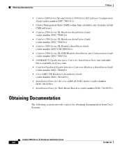
... On the Catalyst 2924M XL, Catalyst 2912MF XL, and Catalyst 2924M XL DC switches, two module slots for 10BASE-T/100BASE-TX, 1000BASE-X, 1000BASE-T, Gigabit Ethernet, and asynchronous transfer mode (ATM) modules • On the Catalyst 2924M XL DC switch, a direct current (DC) power converter • On the Catalyst 2912 LRE...the Cisco LRE customer premises equipment (CPE) devices • Supports up to 2048 MAC addresses on the Catalyst 2924 XL, 2924C XL, and 2912 XL switches • Supports up to 8192 MAC addresses on the Catalyst 2924M XL, Catalyst 2924M XL DC and Catalyst 2912MF XL switches ...
... On the Catalyst 2924M XL, Catalyst 2912MF XL, and Catalyst 2924M XL DC switches, two module slots for 10BASE-T/100BASE-TX, 1000BASE-X, 1000BASE-T, Gigabit Ethernet, and asynchronous transfer mode (ATM) modules • On the Catalyst 2924M XL DC switch, a direct current (DC) power converter • On the Catalyst 2912 LRE...the Cisco LRE customer premises equipment (CPE) devices • Supports up to 2048 MAC addresses on the Catalyst 2924 XL, 2924C XL, and 2912 XL switches • Supports up to 8192 MAC addresses on the Catalyst 2924M XL, Catalyst 2924M XL DC and Catalyst 2912MF XL switches ...

Hardware Installation Guide
Page 24
... twelve 100BASE-FX ports (See Figure 1-3), two module slots (see Figure 1-3), and up to monitor and control the switch and switch cluster members. The switch supports a comprehensive set of MIB extensions and four Remote Monitoring (RMON) groups. CMS is enhanced to the Catalyst 2900 Series XL and Catalyst 3500 Series XL Software Configuration Guide. and port...
... twelve 100BASE-FX ports (See Figure 1-3), two module slots (see Figure 1-3), and up to monitor and control the switch and switch cluster members. The switch supports a comprehensive set of MIB extensions and four Remote Monitoring (RMON) groups. CMS is enhanced to the Catalyst 2900 Series XL and Catalyst 3500 Series XL Software Configuration Guide. and port...
Hardware Installation Guide
Page 25
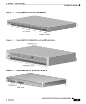
... 21X 22X Catalyst10209B0AS0ES-FEXRIES XL 23 24 10/100 ports 100BASE-FX ports Figure 1-3 Catalyst 2900 XL 100BASE-FX ports and Module Slots Expansion slots 47286 12 1 MODE 2 3 Catalyst 2900 SERIES XL 4 5 100BASE-FX 6 7 8 9 10 11 12 100BASE-FX ports Figure 1-4 Catalyst 2900 LRE XL 10/100 and LRE Ports INPUT OUTPUT PWR PWR RESET TEMP...
... 21X 22X Catalyst10209B0AS0ES-FEXRIES XL 23 24 10/100 ports 100BASE-FX ports Figure 1-3 Catalyst 2900 XL 100BASE-FX ports and Module Slots Expansion slots 47286 12 1 MODE 2 3 Catalyst 2900 SERIES XL 4 5 100BASE-FX 6 7 8 9 10 11 12 100BASE-FX ports Figure 1-4 Catalyst 2900 LRE XL 10/100 and LRE Ports INPUT OUTPUT PWR PWR RESET TEMP...

Hardware Installation Guide
Page 28
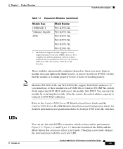
...connected to digital PBX switches that use the 0 to the Installation Notes for the Catalyst 2900 XL hot-swappable modules. Each module port is internally switched to the patch panel. For more information about the Cisco LRE 48 POTS Splitter... (PS-1M-LRE-48), refer to 700 kHz frequency range. For more information about homologated POTS splitters, contact your Cisco sales representative. Module Slots The module...
...connected to digital PBX switches that use the 0 to the Installation Notes for the Catalyst 2900 XL hot-swappable modules. Each module port is internally switched to the patch panel. For more information about the Cisco LRE 48 POTS Splitter... (PS-1M-LRE-48), refer to 700 kHz frequency range. For more information about homologated POTS splitters, contact your Cisco sales representative. Module Slots The module...
Hardware Installation Guide
Page 29
... release required, refer to monitor switch activity and its performance. A power-on expansion modules for Catalyst 2900 series XL switches. Refer to the Catalyst 2900 Series XL Modules Installation Guide and the Catalyst 2900 Series XL ATM Modules Installation and Configuration Guide for the Catalyst 2900 Series XL and Catalyst 3500 Series XL Switches. These modules automatically configure themselves when you install...
... release required, refer to monitor switch activity and its performance. A power-on expansion modules for Catalyst 2900 series XL switches. Refer to the Catalyst 2900 Series XL Modules Installation Guide and the Catalyst 2900 Series XL ATM Modules Installation and Configuration Guide for the Catalyst 2900 Series XL and Catalyst 3500 Series XL Switches. These modules automatically configure themselves when you install...

Hardware Installation Guide
Page 34
...of the 10/100, 100BASE-FX, and LRE ports and module slots have failed. The current bandwidth in a fault condition. Front-Panel Description Chapter 1 Product Overview Table 1-3 RPS LED on the Catalyst 2912 LRE XL and 2924 LRE XL Switches (continued) Color Solid amber Blinking amber RPS Status The ...RPS is providing power to the switch (redundancy has been allocated to this device). Contact Cisco Systems. The internal power supply in a switch has failed, and the RPS is in standby mode or in use by the switch. (See Figure 1-8.) The port duplex mode: full duplex...
...of the 10/100, 100BASE-FX, and LRE ports and module slots have failed. The current bandwidth in a fault condition. Front-Panel Description Chapter 1 Product Overview Table 1-3 RPS LED on the Catalyst 2912 LRE XL and 2924 LRE XL Switches (continued) Color Solid amber Blinking amber RPS Status The ...RPS is providing power to the switch (redundancy has been allocated to this device). Contact Cisco Systems. The internal power supply in a switch has failed, and the RPS is in standby mode or in use by the switch. (See Figure 1-8.) The port duplex mode: full duplex...
Hardware Installation Guide
Page 39
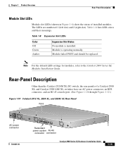
... panels of installed modules. Chapter 1 Product Overview Rear-Panel Description Module Slot LEDs Module slot LEDs (shown in Figure 1-6) show the status of a Catalyst 2900 XL and Catalyst 2900 LRE XL switches have an AC power connector, an RPS connector, and an RJ-45 console port. (See Figure 1-10 through Figure 1-12.) Figure 1-10 Catalyst 2912 XL, 2924...
... panels of installed modules. Chapter 1 Product Overview Rear-Panel Description Module Slot LEDs Module slot LEDs (shown in Figure 1-6) show the status of a Catalyst 2900 XL and Catalyst 2900 LRE XL switches have an AC power connector, an RPS connector, and an RJ-45 console port. (See Figure 1-10 through Figure 1-12.) Figure 1-10 Catalyst 2912 XL, 2924...
Hardware Installation Guide
Page 42
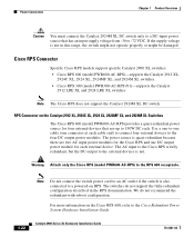
...output power module for four external devices that has an input supply voltage from -36 to -72 VDC. The switches do not recommend the redundant-with-reboot configuration. If the supply voltage is not. Cisco RPS Connector Specific Cisco RPS models support specific Catalyst 2900 XL switches: • Cisco RPS ...are two AC input power modules for the Cisco RPS and one connector at each cable end) to connect four external devices to the four DC output power modules. Power Connectors Chapter 1 Product Overview Caution You must connect the Catalyst 2924M XL DC switch only to a DC-...
...output power module for four external devices that has an input supply voltage from -36 to -72 VDC. The switches do not recommend the redundant-with-reboot configuration. If the supply voltage is not. Cisco RPS Connector Specific Cisco RPS models support specific Catalyst 2900 XL switches: • Cisco RPS ...are two AC input power modules for the Cisco RPS and one connector at each cable end) to connect four external devices to the four DC output power modules. Power Connectors Chapter 1 Product Overview Caution You must connect the Catalyst 2924M XL DC switch only to a DC-...

Hardware Installation Guide
Page 45
... ATM Modules Installation and Configuration Guide for Installation Warnings These warnings are translated into several languages in the order that they are presented: • Pre-installation information and guidelines • Installation procedures • Power-on procedures • Connection procedures • Where to go next Note Refer to install your Catalyst 2900 XL switch...
... ATM Modules Installation and Configuration Guide for Installation Warnings These warnings are translated into several languages in the order that they are presented: • Pre-installation information and guidelines • Installation procedures • Power-on procedures • Connection procedures • Where to go next Note Refer to install your Catalyst 2900 XL switch...

Hardware Installation Guide
Page 48
...-RPS) to the RPS receptacle. Warning Attach only the Cisco RPS (model PWR300-AC-RPS-N1) to the RPS receptacle. EMC Regulatory Statements U.S.A. This is in a residential environment, it may cause radio frequency interference. Catalyst 2900 Series XL Hardware Installation Guide 2-4 78-6461-04 ...Warning Avoid exposure to the laser beam. When used in the front matter of the 100BASE-FX single-mode supervisor engine module. Under such circumstances, the user may be...
...-RPS) to the RPS receptacle. Warning Attach only the Cisco RPS (model PWR300-AC-RPS-N1) to the RPS receptacle. EMC Regulatory Statements U.S.A. This is in a residential environment, it may cause radio frequency interference. Catalyst 2900 Series XL Hardware Installation Guide 2-4 78-6461-04 ...Warning Avoid exposure to the laser beam. When used in the front matter of the 100BASE-FX single-mode supervisor engine module. Under such circumstances, the user may be...

Hardware Installation Guide
Page 51
... all packing materials to Find the Catalyst 2900 XL and Catalyst 3500 XL Documentation flyer • Cisco Documentation CD-ROM • AC power cord 78-6461-04 Catalyst 2900 Series XL Hardware Installation Guide 2-7 Note If the switch is installed in a closed or ...8226; Operating environment is within reach of the expansion modules, refer to the modules documentation in Appendix A, "Technical Specifications." • Airflow around the switch and through the vents is shipped with these conditions: - Your Catalyst 2900 XL switch is unrestricted. • Temperature around it might be...
... all packing materials to Find the Catalyst 2900 XL and Catalyst 3500 XL Documentation flyer • Cisco Documentation CD-ROM • AC power cord 78-6461-04 Catalyst 2900 Series XL Hardware Installation Guide 2-7 Note If the switch is installed in a closed or ...8226; Operating environment is within reach of the expansion modules, refer to the modules documentation in Appendix A, "Technical Specifications." • Airflow around the switch and through the vents is shipped with these conditions: - Your Catalyst 2900 XL switch is unrestricted. • Temperature around it might be...
Hardware Installation Guide
Page 81
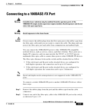
... to 2 kilometers. Connect one end of the 100BASE-FX single-mode supervisor engine module. These ports use a duplex SC connector, and you are ready to another 100BASE-FX device, follow . • If the switch port and the port on the attached device are configured for half-duplex operation, ... the attached device follow these ports to other 100BASE-FX-compatible network devices, such as shown in Figure 2-29. 78-6461-04 Catalyst 2900 Series XL Hardware Installation Guide 2-37 Chapter 2 Installation Connecting to a 100BASE-FX Port Connecting to the laser beam. Avoid exposure and...
... to 2 kilometers. Connect one end of the 100BASE-FX single-mode supervisor engine module. These ports use a duplex SC connector, and you are ready to another 100BASE-FX device, follow . • If the switch port and the port on the attached device are configured for half-duplex operation, ... the attached device follow these ports to other 100BASE-FX-compatible network devices, such as shown in Figure 2-29. 78-6461-04 Catalyst 2900 Series XL Hardware Installation Guide 2-37 Chapter 2 Installation Connecting to a 100BASE-FX Port Connecting to the laser beam. Avoid exposure and...
Hardware Installation Guide
Page 86
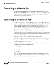
... a kit (part number ACS-DSBUASYN=) containing that adapter from Cisco. The terminal-emulation software-frequently a PC application such as Hyperterminal or Procomm Plus-makes communication between the switch and your PC- Connecting to the Console Port Use the supplied...switch, you want to connect the switch console port to a terminal. You can change the port baud rate to the Catalyst 2900 Series XL Modules Installation Guide and the Catalyst 2900 Series XL ATM Modules Installation and Configuration Guide. Connecting to a Module Port Chapter 2 Installation Connecting to a Module...
... a kit (part number ACS-DSBUASYN=) containing that adapter from Cisco. The terminal-emulation software-frequently a PC application such as Hyperterminal or Procomm Plus-makes communication between the switch and your PC- Connecting to the Console Port Use the supplied...switch, you want to connect the switch console port to a terminal. You can change the port baud rate to the Catalyst 2900 Series XL Modules Installation Guide and the Catalyst 2900 Series XL ATM Modules Installation and Configuration Guide. Connecting to a Module Port Chapter 2 Installation Connecting to a Module...
Hardware Installation Guide
Page 90
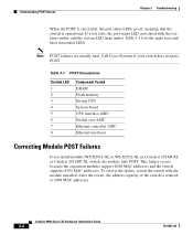
... Cisco Systems if your switch does not pass POST. Table 3-1 POST Descriptions Switch LED 1 2 3 4 5 6 7 8 Component Tested DRAM Flash memory Switch CPU System board CPU interface ASIC Switch core ASIC Ethernet controller ASIC Ethernet interfaces Correcting Module POST Failures If you install modules WS-X2914-XL or WS-X2922-XL in a Catalyst 2924M XL or Catalyst 2912MF XL switch, the module fails...
... Cisco Systems if your switch does not pass POST. Table 3-1 POST Descriptions Switch LED 1 2 3 4 5 6 7 8 Component Tested DRAM Flash memory Switch CPU System board CPU interface ASIC Switch core ASIC Ethernet controller ASIC Ethernet interfaces Correcting Module POST Failures If you install modules WS-X2914-XL or WS-X2922-XL in a Catalyst 2924M XL or Catalyst 2912MF XL switch, the module fails...

Hardware Installation Guide
Page 93
...• The cable is wired incorrectly. • STP checking for the LED to exceed rate or reach selected by the Catalyst 2900 LRE XL switch. Corrupted software. Tighten the thumb screws on . Telephone cable loose or not connected properly. Telephone cable defective. Cable trunking ... Incorrect baud rate. Cisco LRE CPE not communicating with a tested good cable. • Wait 30 seconds for possible loops. • For the correct pinouts and the proper application of crossover or straight-through cables, see which test failed. Amber Module Slot LED. LRE LED...
...• The cable is wired incorrectly. • STP checking for the LED to exceed rate or reach selected by the Catalyst 2900 LRE XL switch. Corrupted software. Tighten the thumb screws on . Telephone cable loose or not connected properly. Telephone cable defective. Cable trunking ... Incorrect baud rate. Cisco LRE CPE not communicating with a tested good cable. • Wait 30 seconds for possible loops. • For the correct pinouts and the proper application of crossover or straight-through cables, see which test failed. Amber Module Slot LED. LRE LED...

Hardware Installation Guide
Page 99
For switches that support modules (Catalyst 2912MF XL and 2924M XL), also refer to the Catalyst 2900 Series XL Modules Installation Guide and the Catalyst 2900 Series XL ATM Modules Installation Guide for the Catalyst 2900 series switches. A A P P E N D I X Technical Specifications Table A-1, Table A-2, Table A-3, and Table A-5 list the technical specifications for additional specifications. Table A-6 lists the agency approvals for EMI and safety. 78-6461-04 Catalyst 2900 Series XL Hardware Installation Guide A-1
For switches that support modules (Catalyst 2912MF XL and 2924M XL), also refer to the Catalyst 2900 Series XL Modules Installation Guide and the Catalyst 2900 Series XL ATM Modules Installation Guide for the Catalyst 2900 series switches. A A P P E N D I X Technical Specifications Table A-1, Table A-2, Table A-3, and Table A-5 list the technical specifications for additional specifications. Table A-6 lists the agency approvals for EMI and safety. 78-6461-04 Catalyst 2900 Series XL Hardware Installation Guide A-1
Hardware Installation Guide
Page 100
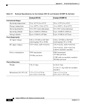
...Technical Specifications Table A-1 Technical Specifications for the Catalyst 2912 XL and Catalyst 2912MF XL Switches Environmental Ranges Operating temperature Storage temperature Operating humidity Operating altitude Storage altitude Power Requirements AC input voltage DC input voltages Catalyst 2912 XL 32 to 113°F (0 ... +12V @0.75A with two modules installed 90W (maximum) 307 Btus per hour 170W with two modules installed 580 Btus per hour 14 lb (6.3 kg) 15.5 lb (7.1 kg) with two modules installed 3.46 x 17.5 x 12 in. (8.8 x 44.5 x 30.5 cm) Catalyst 2900 Series XL Hardware Installation...
...Technical Specifications Table A-1 Technical Specifications for the Catalyst 2912 XL and Catalyst 2912MF XL Switches Environmental Ranges Operating temperature Storage temperature Operating humidity Operating altitude Storage altitude Power Requirements AC input voltage DC input voltages Catalyst 2912 XL 32 to 113°F (0 ... +12V @0.75A with two modules installed 90W (maximum) 307 Btus per hour 170W with two modules installed 580 Btus per hour 14 lb (6.3 kg) 15.5 lb (7.1 kg) with two modules installed 3.46 x 17.5 x 12 in. (8.8 x 44.5 x 30.5 cm) Catalyst 2900 Series XL Hardware Installation...