
Installation Guide
Page 7
...Switch 2-10 Attaching the Brackets to the Switch 2-11 Mounting the Switch in a Rack 2-13 Attaching the Optional Cable Guide 2-13 Installing the Switch on a Wall 2-15 Attaching the Brackets to the Switch 2-15 Attaching the Switch to a Wall 2-16 Installing the Switch on a Table or Shelf 2-17 Powering On the Switch... Module Port 2-21 Connecting to a GigaStack GBIC Module Port 2-22 Connecting a PC or Terminal to the Console Port 2-23 Assigning Switch Information 2-24 Using the Setup Program 2-25 Using BOOTP 2-29 Default Configuration Settings 2-29 Where to Go Next 2-31 Troubleshooting 3-1 ...
...Switch 2-10 Attaching the Brackets to the Switch 2-11 Mounting the Switch in a Rack 2-13 Attaching the Optional Cable Guide 2-13 Installing the Switch on a Wall 2-15 Attaching the Brackets to the Switch 2-15 Attaching the Switch to a Wall 2-16 Installing the Switch on a Table or Shelf 2-17 Powering On the Switch... Module Port 2-21 Connecting to a GigaStack GBIC Module Port 2-22 Connecting a PC or Terminal to the Console Port 2-23 Assigning Switch Information 2-24 Using the Setup Program 2-25 Using BOOTP 2-29 Default Configuration Settings 2-29 Where to Go Next 2-31 Troubleshooting 3-1 ...
Installation Guide
Page 8
...) C-2 Attaching the Cisco RPS (model PWR300-AC-RPS-N1) C-4 Service Personnel Warning C-5 Qualified Personnel Warning C-7 Installation Instructions Warning C-9 Jewelry Removal Warning C-10 Stacking the Chassis Warning C-13 Main Disconnecting Device C-15 Overtemperature Warning C-16 TN Power Warning C-19 Ground Connection Warning C-20 Circuit Breaker (15A) Warning C-21 Catalyst 3500 Series XL Hardware Installation...
...) C-2 Attaching the Cisco RPS (model PWR300-AC-RPS-N1) C-4 Service Personnel Warning C-5 Qualified Personnel Warning C-7 Installation Instructions Warning C-9 Jewelry Removal Warning C-10 Stacking the Chassis Warning C-13 Main Disconnecting Device C-15 Overtemperature Warning C-16 TN Power Warning C-19 Ground Connection Warning C-20 Circuit Breaker (15A) Warning C-21 Catalyst 3500 Series XL Hardware Installation...

Installation Guide
Page 12
... 1, "Product Overview," is in boldface screen font. • Nonprinting characters, such as passwords or tabs, are in angle brackets (< >). Catalyst 3500 Series XL Hardware Installation Guide xii 78-6456-04 Examples of the switch. Appendix B, "Connector and Cable Specifications," describes the connectors, cables, and adapters that might arise when you supply values are installing the...
... 1, "Product Overview," is in boldface screen font. • Nonprinting characters, such as passwords or tabs, are in angle brackets (< >). Catalyst 3500 Series XL Hardware Installation Guide xii 78-6456-04 Examples of the switch. Appendix B, "Connector and Cable Specifications," describes the connectors, cables, and adapters that might arise when you supply values are installing the...
Installation Guide
Page 18
... change configuration settings and to display switch information. Online help also provides detailed information about Catalyst 3500 series XL switches and related products, refer to the following publications: • Quick Start: Catalyst 3500 Series XL Cabling and Setup • Cisco IOS Desktop Switching Software Configuration Guide • Cisco IOS Desktop Switching Command Reference (online only) • Cisco Cluster Management Suite online help...
... change configuration settings and to display switch information. Online help also provides detailed information about Catalyst 3500 series XL switches and related products, refer to the following publications: • Quick Start: Catalyst 3500 Series XL Cabling and Setup • Cisco IOS Desktop Switching Software Configuration Guide • Cisco IOS Desktop Switching Command Reference (online only) • Cisco Cluster Management Suite online help...

Installation Guide
Page 31
... such as workstations, Cisco IP Phones, and hubs through standard RJ-45 connectors and Category 3, 4, or 5 cabling 78-6456-04 Catalyst 3500 Series XL Hardware Installation Guide 1-7 The 10/100 switch ports can connect, up to a distance of the pair (port 1) is above the second member (port 2). Chapter 1 Product Overview Figure 1-5 Catalyst 3524-PWR XL Switch Front-Panel Description 30291...
... such as workstations, Cisco IP Phones, and hubs through standard RJ-45 connectors and Category 3, 4, or 5 cabling 78-6456-04 Catalyst 3500 Series XL Hardware Installation Guide 1-7 The 10/100 switch ports can connect, up to a distance of the pair (port 1) is above the second member (port 2). Chapter 1 Product Overview Figure 1-5 Catalyst 3524-PWR XL Switch Front-Panel Description 30291...
Installation Guide
Page 32
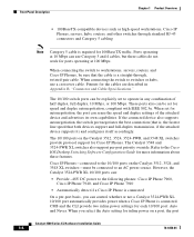
... Phones. When connecting the switch to the following phones: Cisco IP Phone 7960, Cisco IP Phone 7940, and Cisco IP Phone 7910 • Automatically detect if a Cisco IP Phone is a straight-through standard RJ-45 connectors and Category 5 cabling Note Category 5 cable is connected. The 10/100 ports on the Catalyst 3512, 3524, 3524-PWR, and 3548 XL switches provide protocol support for...
... Phones. When connecting the switch to the following phones: Cisco IP Phone 7960, Cisco IP Phone 7940, and Cisco IP Phone 7910 • Automatically detect if a Cisco IP Phone is a straight-through standard RJ-45 connectors and Category 5 cabling Note Category 5 cable is connected. The 10/100 ports on the Catalyst 3512, 3524, 3524-PWR, and 3548 XL switches provide protocol support for...
Installation Guide
Page 33
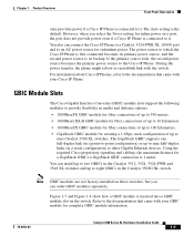
...the required Cisco proprietary signaling and cabling, the maximum distance for a GigaStack GBIC-to-GigaStack GBIC connection is the default. Note GBIC modules are not factory-installed on these switches, but you select the Never setting for creating a 1-Gbps stack configuration of up to the Cisco IP ...primary power source, and the second power source is connected to the documentation that came with the switch. However, when you can connect the Cisco IP Phone to a Catalyst 3524-PWR XL 10/100 port and to other Gigabit Ethernet devices. During the power transfer, the phone might ...
...the required Cisco proprietary signaling and cabling, the maximum distance for a GigaStack GBIC-to-GigaStack GBIC connection is the default. Note GBIC modules are not factory-installed on these switches, but you select the Never setting for creating a 1-Gbps stack configuration of up to the Cisco IP ...primary power source, and the second power source is connected to the documentation that came with the switch. However, when you can connect the Cisco IP Phone to a Catalyst 3524-PWR XL 10/100 port and to other Gigabit Ethernet devices. During the power transfer, the phone might ...
Installation Guide
Page 47
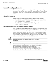
...powered-on RPS. Cisco RPS Connector Specific Cisco RPS models support specific Catalyst 3500 XL switches: • Cisco RPS 600 (model PWR600-AC-RPS)-Supports the Catalyst 3512, 3524, 3548, and 3508 XL switches • Cisco RPS 300 (model PWR300-AC-RPS)-Supports the Catalyst 3524-PWR XL switch RPS Connector on the Cisco RPS 600, refer... 240 VAC. For more information on the Catalyst 3508, 3512, 3524, and 3548 XL Switches The Cisco RPS 600 (model PWR600-AC-RPS) provides a quasi-redundant power source for the Cisco RPS and one connector at each cable end) to connect four external devices to ...
...powered-on RPS. Cisco RPS Connector Specific Cisco RPS models support specific Catalyst 3500 XL switches: • Cisco RPS 600 (model PWR600-AC-RPS)-Supports the Catalyst 3512, 3524, 3548, and 3508 XL switches • Cisco RPS 300 (model PWR300-AC-RPS)-Supports the Catalyst 3524-PWR XL switch RPS Connector on the Cisco RPS 600, refer... 240 VAC. For more information on the Catalyst 3508, 3512, 3524, and 3548 XL Switches The Cisco RPS 600 (model PWR600-AC-RPS) provides a quasi-redundant power source for the Cisco RPS and one connector at each cable end) to connect four external devices to ...
Installation Guide
Page 48
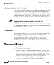
... Guide and the online help for up to create, monitor, and configure a cluster of switches or an individual switch. Management Options Chapter 1 Product Overview RPS Connector on the Catalyst 3524-PWR XL Switch The Cisco RPS 300 (model PWR300-AC-RPS) has two output levels: -48V and 12V with ...application to the RPS receptacle. For console port and adapter pinout information, see the "Cable and Adapter Specifications" section on the Cisco RPS 300, refer to a PC by means of the switches has experienced power failure and automatically sends power to a terminal. You use the Cluster...
... Guide and the online help for up to create, monitor, and configure a cluster of switches or an individual switch. Management Options Chapter 1 Product Overview RPS Connector on the Catalyst 3524-PWR XL Switch The Cisco RPS 300 (model PWR300-AC-RPS) has two output levels: -48V and 12V with ...application to the RPS receptacle. For console port and adapter pinout information, see the "Cable and Adapter Specifications" section on the Cisco RPS 300, refer to a PC by means of the switches has experienced power failure and automatically sends power to a terminal. You use the Cluster...
Installation Guide
Page 55
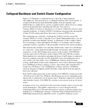
... also is connected. Cisco CallManager controls call -processing server running Cisco SoftPhone software can manage a cluster through , twisted-pair cable with RJ-45 connectors-to the 10/100 inline-power ports on the Catalyst 3524-PWR XL switches and to switches other than the Catalyst 3524-PWR XL switches receive power from their PCs. Using Cisco IP Phones, Cisco CallManager software, and Cisco SoftPhone software integrates telephony...
... also is connected. Cisco CallManager controls call -processing server running Cisco SoftPhone software can manage a cluster through , twisted-pair cable with RJ-45 connectors-to the 10/100 inline-power ports on the Catalyst 3524-PWR XL switches and to switches other than the Catalyst 3524-PWR XL switches receive power from their PCs. Using Cisco IP Phones, Cisco CallManager software, and Cisco SoftPhone software integrates telephony...
Installation Guide
Page 62
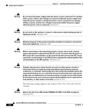
... within the power supply when the power cord is connected. Statement 1072 The following warning applies to the Catalyst 3508, 3512, 3524, and 3548 XL switches: Warning Attach only the Cisco RPS (model PWR600-AC-RPS) to the chassis, ensure that all national laws and regulations. For systems... or disconnect cables during periods of the circuit breaker in a restricted access location and users and service people who are present within the power supply even when the power switch is off and the power cord is connected. Statement 100 Catalyst 3500 Series XL Hardware Installation ...
... within the power supply when the power cord is connected. Statement 1072 The following warning applies to the Catalyst 3508, 3512, 3524, and 3548 XL switches: Warning Attach only the Cisco RPS (model PWR600-AC-RPS) to the chassis, ensure that all national laws and regulations. For systems... or disconnect cables during periods of the circuit breaker in a restricted access location and users and service people who are present within the power supply even when the power switch is off and the power cord is connected. Statement 100 Catalyst 3500 Series XL Hardware Installation ...

Installation Guide
Page 65
... protection distance are up to the document that came with your GBICs. • For the GigaStack GBIC ports, cable lengths from the switch to the connected devices are used and installed properly according to the Hungarian EMC Class A requirements (MSZEN55022). Class ...within the ranges listed in Appendix A, "Technical Specifications." 78-6456-04 Catalyst 3500 Series XL Hardware Installation Guide 2-7 Statement 256 Installation Guidelines When determining where to place the switch, be used . For specific cable lengths, refer to the documents that came with the GigaStack GBIC. &#...
... protection distance are up to the document that came with your GBICs. • For the GigaStack GBIC ports, cable lengths from the switch to the connected devices are used and installed properly according to the Hungarian EMC Class A requirements (MSZEN55022). Class ...within the ranges listed in Appendix A, "Technical Specifications." 78-6456-04 Catalyst 3500 Series XL Hardware Installation Guide 2-7 Statement 256 Installation Guidelines When determining where to place the switch, be used . For specific cable lengths, refer to the documents that came with the GigaStack GBIC. &#...
Installation Guide
Page 66
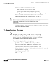
... assembly, the temperature around the unit does not exceed 113°F (45°C). The switch is shipped with the following items: • Quick Start: Catalyst 3500 Series XL Cabling and Setup • This Catalyst 3500 Series XL Hardware Installation Guide • Cisco IOS Desktop Switching Software Configuration Guide • Release Notes for Installation Chapter 2 Installing and Starting Up...
... assembly, the temperature around the unit does not exceed 113°F (45°C). The switch is shipped with the following items: • Quick Start: Catalyst 3500 Series XL Cabling and Setup • This Catalyst 3500 Series XL Hardware Installation Guide • Cisco IOS Desktop Switching Software Configuration Guide • Release Notes for Installation Chapter 2 Installing and Starting Up...

Installation Guide
Page 67
... the mounting brackets • One RJ-45-to-RJ-45 rollover cable • One RJ-45-to-DB-9 female adapter • Cisco Information Packet, containing warranty, safety, and support information Installing the Switch in a Rack Warning To prevent bodily injury when mounting or servicing... this unit in a rack, you must take special precautions to the rack. 78-6456-04 Catalyst 3500 Series XL Hardware Installation ...
... the mounting brackets • One RJ-45-to-RJ-45 rollover cable • One RJ-45-to-DB-9 female adapter • Cisco Information Packet, containing warranty, safety, and support information Installing the Switch in a Rack Warning To prevent bodily injury when mounting or servicing... this unit in a rack, you must take special precautions to the rack. 78-6456-04 Catalyst 3500 Series XL Hardware Installation ...

Installation Guide
Page 68
... 2 Installing and Starting Up the Switch Note The illustrations in the series (Catalyst 3512, 3524, 3524-PWR, and 3548 XL) can be installed as an example. Figure 2-2 shows how to remove the chassis screw from the Switch If you plan to the switch • Mounting the switch in a rack • Attaching the optional cable guide Removing Screws from one side...
... 2 Installing and Starting Up the Switch Note The illustrations in the series (Catalyst 3512, 3524, 3524-PWR, and 3548 XL) can be installed as an example. Figure 2-2 shows how to remove the chassis screw from the Switch If you plan to the switch • Mounting the switch in a rack • Attaching the optional cable guide Removing Screws from one side...

Installation Guide
Page 71
... attaching the cable guides to the switch. Figure 2-5 Mounting the Switch in a Rack 26233 1 SYSTEM 2 3 RPS 4 5 MODE STATUS 6 7 UTIL 8 DUPLX SPEED Phillips machine screws After the switch is connected, the System LED turns amber for installation instructions. If you are attached to the left or right bracket. 78-6456-04 Catalyst 3500 Series XL Hardware Installation...
... attaching the cable guides to the switch. Figure 2-5 Mounting the Switch in a Rack 26233 1 SYSTEM 2 3 RPS 4 5 MODE STATUS 6 7 UTIL 8 DUPLX SPEED Phillips machine screws After the switch is connected, the System LED turns amber for installation instructions. If you are attached to the left or right bracket. 78-6456-04 Catalyst 3500 Series XL Hardware Installation...

Installation Guide
Page 72
... a Rack Chapter 2 Installing and Starting Up the Switch Note The Catalyst 3548 XL switch ships with a special cable guide as shown in Figure 2-7. This cable guide secures up to a 3548 XL Switch SYSTEM RPS 12 1X 34 56 78 9 10 11 12 13 14 15 16 ...34X 48X 2 Cable guide screw 28324 2-14 Catalyst 3500 Series XL Hardware Installation Guide 78-6456-04 Figure 2-6 Attaching the Cable Guide to a 3512, 3524, 3524-PWR, or 3508 XL Switch 1 MODE SYSTEM RPS 2 3 4 5 STATUS UTIL DUPLX SPEED 6 7 8 Cable guide screw Figure 2-7 Attaching the Cable Guide to 48 cables. Use the supplied...
... a Rack Chapter 2 Installing and Starting Up the Switch Note The Catalyst 3548 XL switch ships with a special cable guide as shown in Figure 2-7. This cable guide secures up to a 3548 XL Switch SYSTEM RPS 12 1X 34 56 78 9 10 11 12 13 14 15 16 ...34X 48X 2 Cable guide screw 28324 2-14 Catalyst 3500 Series XL Hardware Installation Guide 78-6456-04 Figure 2-6 Attaching the Cable Guide to a 3512, 3524, 3524-PWR, or 3508 XL Switch 1 MODE SYSTEM RPS 2 3 4 5 STATUS UTIL DUPLX SPEED 6 7 8 Cable guide screw Figure 2-7 Attaching the Cable Guide to 48 cables. Use the supplied...
Installation Guide
Page 74
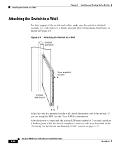
... Cisco RPS documentation. Installing the Switch on page 2-17. 2-16 Catalyst 3500 Series XL Hardware Installation Guide 78-6456-04 After the power is mounted on the wall, attach the power cord to a firmly attached plywood mounting backboard, as shown in the "Powering On the Switch ... 2 Vertical wall-mount 1 STATUS UTIL DUPLEX SPEED SYSTEM RPS MODE 30061 After the switch is connected, the system LED turns amber for 2 seconds, and then it flashes green while the switch completes a series of the switch and cables, make sure the switch is attached securely to a wall stud or to the...
... Cisco RPS documentation. Installing the Switch on page 2-17. 2-16 Catalyst 3500 Series XL Hardware Installation Guide 78-6456-04 After the power is mounted on the wall, attach the power cord to a firmly attached plywood mounting backboard, as shown in the "Powering On the Switch ... 2 Vertical wall-mount 1 STATUS UTIL DUPLEX SPEED SYSTEM RPS MODE 30061 After the switch is connected, the system LED turns amber for 2 seconds, and then it flashes green while the switch completes a series of the switch and cables, make sure the switch is attached securely to a wall stud or to the...
Installation Guide
Page 77
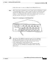
... 56 78 9 10 11 12 11X 12X 22001 Note The Catalyst 3524-PWR XL switch can connect to a Cisco IP Phone through a straight-through Category 5 cable to an RJ-45 connector on page B-4. Pinouts for information about connecting devices to the Catalyst 3524-PWR XL switch. Chapter 2 Installing and Starting Up the Switch Connecting to the 10/100 Ports Follow these steps to...
... 56 78 9 10 11 12 11X 12X 22001 Note The Catalyst 3524-PWR XL switch can connect to a Cisco IP Phone through a straight-through Category 5 cable to an RJ-45 connector on page B-4. Pinouts for information about connecting devices to the Catalyst 3524-PWR XL switch. Chapter 2 Installing and Starting Up the Switch Connecting to the 10/100 Ports Follow these steps to...

Installation Guide
Page 78
... Gigabit Interface Converter Hardware Installation Guide. 2-20 Catalyst 3500 Series XL Hardware Installation Guide 78-6456-04 Connecting to the 1000BaseX ports. Connecting to the GBIC Module Ports Chapter 2 Installing and Starting Up the Switch Step 2 Step 3 Step 4 Connect the other end of the cable to cabling problems. Reconfigure and reboot the connected device if...
... Gigabit Interface Converter Hardware Installation Guide. 2-20 Catalyst 3500 Series XL Hardware Installation Guide 78-6456-04 Connecting to the 1000BaseX ports. Connecting to the GBIC Module Ports Chapter 2 Installing and Starting Up the Switch Step 2 Step 3 Step 4 Connect the other end of the cable to cabling problems. Reconfigure and reboot the connected device if...

