Installation Guide
Page 55
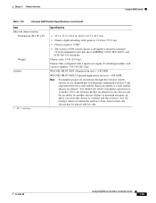
... • Chassis depth including cable guide is 21.64 in. (55.0 cm). • Chassis requires 15 RU1. • The Catalyst 6509 switch chassis is designed to install in which the airflow is from front to fail. You should also allow a minimum separation of 12 ... hot air exhaust on one chassis and the air intake on another chassis. Chapter 1 Product Overview Catalyst 6509 Switch Table 1-12 Catalyst 6509 Switch Specifications (continued) Item Physical characteristics Dimensions (H x W x D) Weight Airflow 1. Chassis only: 55 lb (24.9 kg). Chassis fully configured with 1 supervisor engine, ...
... • Chassis depth including cable guide is 21.64 in. (55.0 cm). • Chassis requires 15 RU1. • The Catalyst 6509 switch chassis is designed to install in which the airflow is from front to fail. You should also allow a minimum separation of 12 ... hot air exhaust on one chassis and the air intake on another chassis. Chapter 1 Product Overview Catalyst 6509 Switch Table 1-12 Catalyst 6509 Switch Specifications (continued) Item Physical characteristics Dimensions (H x W x D) Weight Airflow 1. Chassis only: 55 lb (24.9 kg). Chassis fully configured with 1 supervisor engine, ...
Installation Guide
Page 61
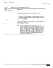
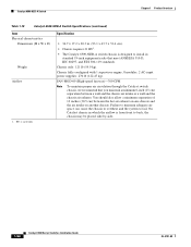
...310-D, IEC 60297, and ETS 300-119 standards. OL-5781-08 Catalyst 6500 Series Switches Installation Guide 1-41 Chapter 1 Product Overview Catalyst 6509-E Switch Table 1-14 Catalyst 6509-E Switch Specifications (continued) Item Physical characteristics Dimensions (H x W x D) Weight Airflow 1. Chassis only: 60 lb (27.3 kg). You should ... which the airflow is designed to install in . (55.0 cm). • Chassis requires 15 RU1. • The Catalyst 6509-E switch chassis is from front to fail. Chassis fully configured with 1 supervisor engine, 8 switching modules, and 2 power ...
...310-D, IEC 60297, and ETS 300-119 standards. OL-5781-08 Catalyst 6500 Series Switches Installation Guide 1-41 Chapter 1 Product Overview Catalyst 6509-E Switch Table 1-14 Catalyst 6509-E Switch Specifications (continued) Item Physical characteristics Dimensions (H x W x D) Weight Airflow 1. Chassis only: 60 lb (27.3 kg). You should ... which the airflow is designed to install in . (55.0 cm). • Chassis requires 15 RU1. • The Catalyst 6509-E switch chassis is from front to fail. Chassis fully configured with 1 supervisor engine, 8 switching modules, and 2 power ...
Installation Guide
Page 68
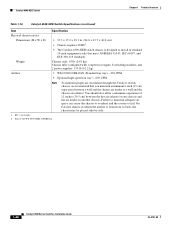
... system to back, the chassis may be placed side-by-side. 1. RU = rack units. 2. Weight Chassis only: 55 lb (24.9 kg). On Catalyst chassis in standard 19-inch equipment racks that you maintain a minimum 6-inch (15 cm) separation between... the hot air exhaust on one chassis and the air intake on another chassis. Catalyst 6509-NEB Switch Chapter 1 Product Overview Table 1-16 Catalyst 6509-NEB Switch Specifications (continued) Item Specification Physical characteristics Dimensions (H x W x D) • 33.3 x 17.2 x 18.1 in. ...
... system to back, the chassis may be placed side-by-side. 1. RU = rack units. 2. Weight Chassis only: 55 lb (24.9 kg). On Catalyst chassis in standard 19-inch equipment racks that you maintain a minimum 6-inch (15 cm) separation between... the hot air exhaust on one chassis and the air intake on another chassis. Catalyst 6509-NEB Switch Chapter 1 Product Overview Table 1-16 Catalyst 6509-NEB Switch Specifications (continued) Item Specification Physical characteristics Dimensions (H x W x D) • 33.3 x 17.2 x 18.1 in. ...
Installation Guide
Page 74
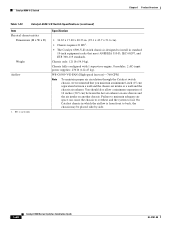
...8226; 36.7 x 17.2 x 20.3 in. (93.1 x 43.7 x 51.6 cm). • Chassis requires 21 RU1. • The Catalyst 6509-NEB-A switch chassis is designed to install in which the airflow is from front to fail. Failure to maintain adequate air space can cause the...maintain proper air circulation through the Catalyst switch chassis, we recommend that meet ANSI/EIA 310-D, IEC 60297, and ETS 300-119 standards. Catalyst 6509-NEB-A Switch Chapter 1 Product Overview Table 1-18 Catalyst 6509-NEB-A Switch Specifications (continued) Item Physical characteristics Dimensions (H x W x D) Weight Airflow 1.
...8226; 36.7 x 17.2 x 20.3 in. (93.1 x 43.7 x 51.6 cm). • Chassis requires 21 RU1. • The Catalyst 6509-NEB-A switch chassis is designed to install in which the airflow is from front to fail. Failure to maintain adequate air space can cause the...maintain proper air circulation through the Catalyst switch chassis, we recommend that meet ANSI/EIA 310-D, IEC 60297, and ETS 300-119 standards. Catalyst 6509-NEB-A Switch Chapter 1 Product Overview Table 1-18 Catalyst 6509-NEB-A Switch Specifications (continued) Item Physical characteristics Dimensions (H x W x D) Weight Airflow 1.
Installation Guide
Page 80
... chassis, we recommend that meet ANSI/EIA 310-D, IEC 60297, and ETS 300-119 standards. Catalyst 6509-V-E Switch Chapter 1 Product Overview Table 1-20 Catalyst 6509-V-E Switch Specifications (continued) Item Physical characteristics Dimensions (H x W x D) Weight Airflow 1. Failure to maintain adequate air space can cause the chassis to overheat and the system to back, the chassis may be...
... chassis, we recommend that meet ANSI/EIA 310-D, IEC 60297, and ETS 300-119 standards. Catalyst 6509-V-E Switch Chapter 1 Product Overview Table 1-20 Catalyst 6509-V-E Switch Specifications (continued) Item Physical characteristics Dimensions (H x W x D) Weight Airflow 1. Failure to maintain adequate air space can cause the chassis to overheat and the system to back, the chassis may be...
Installation Guide
Page 141
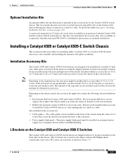
... installed on your own. Two cable guides can be prethreaded to install the Catalyst 6509-E chassis as part of the chassis. Installation Accessory Kits The Catalyst 6509 and Catalyst 6509-E switch chassis are secured to secure the chassis in the rack enclosure. This kit can be installed on the... front of the chassis using the same sets of screws that are used to support the weight of the chassis ...
... installed on your own. Two cable guides can be prethreaded to install the Catalyst 6509-E chassis as part of the chassis. Installation Accessory Kits The Catalyst 6509 and Catalyst 6509-E switch chassis are secured to secure the chassis in the rack enclosure. This kit can be installed on the... front of the chassis using the same sets of screws that are used to support the weight of the chassis ...
Installation Guide
Page 142
... left and right. The shelf kit supports the weight of installation. You need to identify them as an alternative method of the chassis while you install the chassis in the rack. Installing a Catalyst 6509 or Catalyst 6509-E Switch Chassis Chapter 3 Installing the Switch Note... Catalyst 6500 Series Switches Installation Guide OL-5781-08 The procedure for both the Catalyst 6509 and the Catalyst 6509-E switch chassis. Note The L brackets for the Catalyst 6509 and the Catalyst 6509-E switches are stamped with an L and an R to install this kit first before you install and secure ...
... left and right. The shelf kit supports the weight of installation. You need to identify them as an alternative method of the chassis while you install the chassis in the rack. Installing a Catalyst 6509 or Catalyst 6509-E Switch Chassis Chapter 3 Installing the Switch Note... Catalyst 6500 Series Switches Installation Guide OL-5781-08 The procedure for both the Catalyst 6509 and the Catalyst 6509-E switch chassis. Note The L brackets for the Catalyst 6509 and the Catalyst 6509-E switches are stamped with an L and an R to install this kit first before you install and secure ...
Installation Guide
Page 146
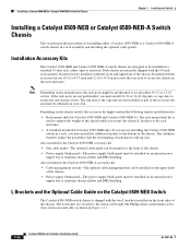
... optional cable management kit can be mounted to the front of the chassis. Installation Accessory Kits The Catalyst 6509-NEB and Catalyst 6509-NEB-A switch chassis are used to support the weight of the chassis while you must install 10-32 or 12-24 clip nuts or cage nuts to...the accessory kit might be installed on an unused power supply bay to accept either a Catalyst 6509-NEB or a Catalyst 6509-NEB-A switch chassis in the rack enclosure. The clip nuts or the cage nuts are secured to secure the chassis in a rack assembly and installing the optional cable guides. Also included in a...
... optional cable management kit can be mounted to the front of the chassis. Installation Accessory Kits The Catalyst 6509-NEB and Catalyst 6509-NEB-A switch chassis are used to support the weight of the chassis while you must install 10-32 or 12-24 clip nuts or cage nuts to...the accessory kit might be installed on an unused power supply bay to accept either a Catalyst 6509-NEB or a Catalyst 6509-NEB-A switch chassis in the rack enclosure. The clip nuts or the cage nuts are secured to secure the chassis in a rack assembly and installing the optional cable guides. Also included in a...
Installation Guide
Page 148
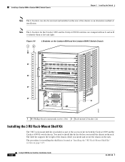
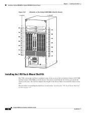
... shelf kit supports the weight of the accessory kit for installing the shelf kit is included as part of the chassis while you install the chassis in the rack. Chapter 3 Installing the Switch L Brackets on page 3-47. The procedure for both the Catalyst 6509-NEB and the Catalyst 6509-NEB-A switch chassis. ... 3 RU Rack-Mount Shelf Kit The 3 RU rack-mount shelf kit is located in the "Installing the 3 RU Rack-Mount Shelf Kit" section on the Catalyst 6509-NEB-A Switch Chassis L bracket 79896 WS-X6548-GE-TX 1 11 13 23 25 35 37 47 2 12 14 24 26 36 38 48 STATUS 1 2 3 4 5 6 ...
... shelf kit supports the weight of the accessory kit for installing the shelf kit is included as part of the chassis while you install the chassis in the rack. Chapter 3 Installing the Switch L Brackets on page 3-47. The procedure for both the Catalyst 6509-NEB and the Catalyst 6509-NEB-A switch chassis. ... 3 RU Rack-Mount Shelf Kit The 3 RU rack-mount shelf kit is located in the "Installing the 3 RU Rack-Mount Shelf Kit" section on the Catalyst 6509-NEB-A Switch Chassis L bracket 79896 WS-X6548-GE-TX 1 11 13 23 25 35 37 47 2 12 14 24 26 36 38 48 STATUS 1 2 3 4 5 6 ...
Installation Guide
Page 156
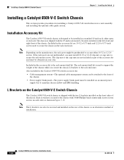
... nuts are not included as an alternative method of the chassis. L Brackets on the Catalyst 6509-V-E Switch Chassis The Catalyst 6509-V-E switch chassis is shipped with the two L brackets installed on an unused power supply bay to secure the rack-mount screws. If the rack posts are 10-32 x 0.75-inch and... 12-24 x 0.75-inch screws used to support the weight of the chassis. • Power supply ...
... nuts are not included as an alternative method of the chassis. L Brackets on the Catalyst 6509-V-E Switch Chassis The Catalyst 6509-V-E switch chassis is shipped with the two L brackets installed on an unused power supply bay to secure the rack-mount screws. If the rack posts are 10-32 x 0.75-inch and... 12-24 x 0.75-inch screws used to support the weight of the chassis. • Power supply ...

Installation Guide
Page 157
The procedure for the Catalyst 6509-V-E switch chassis. The shelf kit supports the weight of the accessory kit for installing the shelf kit is included as part of the chassis while you install the chassis in the rack. Installing a Catalyst 6509-V-E Switch Chassis L Brackets on page 3-47. You need to install this kit first before you...
The procedure for the Catalyst 6509-V-E switch chassis. The shelf kit supports the weight of the accessory kit for installing the shelf kit is included as part of the chassis while you install the chassis in the rack. Installing a Catalyst 6509-V-E Switch Chassis L Brackets on page 3-47. You need to install this kit first before you...
Installation Guide
Page 167
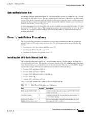
...directly to the rack and help support the weight of the chassis to placed on page 3-50 A center rack-mount kit for 23-inch, telco-style racks is included in multiple Catalyst 6500 series chassis accessory kits. Table 3-3 ...This section describes how to secure them together. The following chassis: • Catalyst 6506 and Catalyst 6506-E • Catalyst 6509 and Catalyst 6509-E • Catalyst 6509-NEB and Catalyst 6509-NEB-A • Catalyst 6509-V-E • Catalyst 6513 and Catalyst 6513-E Table 3-3 lists and describes the contents of the Catalyst 6500 series switch accessory ...
...directly to the rack and help support the weight of the chassis to placed on page 3-50 A center rack-mount kit for 23-inch, telco-style racks is included in multiple Catalyst 6500 series chassis accessory kits. Table 3-3 ...This section describes how to secure them together. The following chassis: • Catalyst 6506 and Catalyst 6506-E • Catalyst 6509 and Catalyst 6509-E • Catalyst 6509-NEB and Catalyst 6509-NEB-A • Catalyst 6509-V-E • Catalyst 6513 and Catalyst 6513-E Table 3-3 lists and describes the contents of the Catalyst 6500 series switch accessory ...
Installation Guide
Page 170
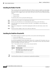
... in the installation kit. Secure the rubber foot to the chassis with the following chassis: • Catalyst 6506-E • Catalyst 6509-E To install the rubber feet kit, perform the following chassis: • Catalyst 6509-NEB switch • Catalyst 6513 switch and Catalyst 6513-E switch If you... must install stabilizer brackets to the bottom of the chassis and support the weight of the...
... in the installation kit. Secure the rubber foot to the chassis with the following chassis: • Catalyst 6506-E • Catalyst 6509-E To install the rubber feet kit, perform the following chassis: • Catalyst 6509-NEB switch • Catalyst 6513 switch and Catalyst 6513-E switch If you... must install stabilizer brackets to the bottom of the chassis and support the weight of the...
Installation Guide
Page 346
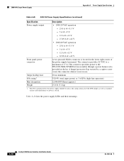
... power) or 3.6 KVA (high-line operation) Heat dissipation 12,046 BTU/hour (approx.) Weight 15.8 lb (7.2 kg) 1. The connector provides 42 VDC at a maximum of the power...switch. A hinged protective flap secured by a captive screw covers the connector when it is located in the lower right corner of 17 A. A-38 Catalyst 6500 Series Switches Installation Guide... OL-5781-08 The kVA rating listed for the power supply should be used as the sizing criteria for both UPS outputs as well as standard circuits and transformers to the WS-6509...
... power) or 3.6 KVA (high-line operation) Heat dissipation 12,046 BTU/hour (approx.) Weight 15.8 lb (7.2 kg) 1. The connector provides 42 VDC at a maximum of the power...switch. A hinged protective flap secured by a captive screw covers the connector when it is located in the lower right corner of 17 A. A-38 Catalyst 6500 Series Switches Installation Guide... OL-5781-08 The kVA rating listed for the power supply should be used as the sizing criteria for both UPS outputs as well as standard circuits and transformers to the WS-6509...
Installation Guide
Page 360
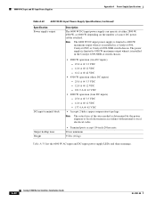
... VDC - 12.0 A @ 12 VDC - 137.4 A @ 42 VDC • Accepts 2-hole copper compression-type lugs. A-52 Catalyst 6500 Series Switches Installation Guide OL-5781-08 Output holdup time Weight • Terminal posts accept 1/4-inch-20 hex nuts. 20 ms minimum 35 lbs (16 kg) Table A-35 list the 6000...4000 W maximum output when it is installed in the Catalyst 6509-NEB-A switch chassis. Note The 6000 W DC-input power supply is limited to 4500 W maximum output when it is installed in a Catalyst 6506, Catalyst 6509, or Catalyst 6509-NEB switch chassis. Note The actual size of source DC...
... VDC - 12.0 A @ 12 VDC - 137.4 A @ 42 VDC • Accepts 2-hole copper compression-type lugs. A-52 Catalyst 6500 Series Switches Installation Guide OL-5781-08 Output holdup time Weight • Terminal posts accept 1/4-inch-20 hex nuts. 20 ms minimum 35 lbs (16 kg) Table A-35 list the 6000...4000 W maximum output when it is installed in the Catalyst 6509-NEB-A switch chassis. Note The 6000 W DC-input power supply is limited to 4500 W maximum output when it is installed in a Catalyst 6506, Catalyst 6509, or Catalyst 6509-NEB switch chassis. Note The actual size of source DC...

Installation Guide
Page 454
... installing 4-3, 4-9, 4-15 specifications A-8 A accessory kit console port cable B-32 contents 3-5, B-32 IN-2 Catalyst 6500 Series Switches Installation Guide repacking C-1 AC-input PEM installing 4-78 removing 4-76 AC-input power cords ... E-4 weight (caution) 4-10 acoustic noise Catalyst 6503-E switches 1-12 Catalyst 6503 switches 1-6 Catalyst 6504-E switches 1-17 Catalyst 6506-E switches 1-28 Catalyst 6506 switches 1-22 Catalyst 6509-E switches 1-40 Catalyst 6509-NEB-A switches 1-53 Catalyst 6509-NEB switches 1-47 Catalyst 6509 switches 1-34 Catalyst 6509-V-E switches 1-59 Catalyst 6513-E...
... installing 4-3, 4-9, 4-15 specifications A-8 A accessory kit console port cable B-32 contents 3-5, B-32 IN-2 Catalyst 6500 Series Switches Installation Guide repacking C-1 AC-input PEM installing 4-78 removing 4-76 AC-input power cords ... E-4 weight (caution) 4-10 acoustic noise Catalyst 6503-E switches 1-12 Catalyst 6503 switches 1-6 Catalyst 6504-E switches 1-17 Catalyst 6506-E switches 1-28 Catalyst 6506 switches 1-22 Catalyst 6509-E switches 1-40 Catalyst 6509-NEB-A switches 1-53 Catalyst 6509-NEB switches 1-47 Catalyst 6509 switches 1-34 Catalyst 6509-V-E switches 1-59 Catalyst 6513-E...
Installation Guide
Page 457
... description 1-52 installation procedure, DC-input 4-15 shock and vibration specifications 1-53 specifications 1-53 supervisor engines 1-50 weight 1-54 Catalyst 6509-NEB switches acoustic noise 1-47 airflow 1-48 airflow (figure) 2-11 environmental specifications 1-47 fan trays 1-45 features...characteristics 1-35 power supplies 1-33 repacking the switch C-1 shock and vibration specifications 1-34 specifications 1-34 supervisor engines 1-31 Catalyst 6509-V-E switches acoustic noise 1-59 airflow 1-60 dimensions, chassis 1-60 environmental specifications 1-59 fan trays 1-57 features table 1-56...
... description 1-52 installation procedure, DC-input 4-15 shock and vibration specifications 1-53 specifications 1-53 supervisor engines 1-50 weight 1-54 Catalyst 6509-NEB switches acoustic noise 1-47 airflow 1-48 airflow (figure) 2-11 environmental specifications 1-47 fan trays 1-45 features...characteristics 1-35 power supplies 1-33 repacking the switch C-1 shock and vibration specifications 1-34 specifications 1-34 supervisor engines 1-31 Catalyst 6509-V-E switches acoustic noise 1-59 airflow 1-60 dimensions, chassis 1-60 environmental specifications 1-59 fan trays 1-57 features table 1-56...
Installation Guide
Page 459
... and replacing 4-9 troubleshooting E-4 weight (caution) 4-20 DC-input power supply installing 4-18, 4-81 differential mode delay See DMD dimensions, chassis Catalyst 6503-E switches 1-12 Catalyst 6503 switches 1-7 Catalyst 6504-E switches 1-17 Catalyst 6506-E switches 1-29 Catalyst 6506 switches 1-23 Catalyst 6509-E switches 1-41 Catalyst 6509-NEB-A switches 1-54 Catalyst 6509-NEB switches 1-48 Catalyst 6509 switches 1-35 Catalyst 6509-V-E switches 1-60 Catalyst 6513-E switches 1-73 Catalyst 6513 switches 1-67 DMD...
... and replacing 4-9 troubleshooting E-4 weight (caution) 4-20 DC-input power supply installing 4-18, 4-81 differential mode delay See DMD dimensions, chassis Catalyst 6503-E switches 1-12 Catalyst 6503 switches 1-7 Catalyst 6504-E switches 1-17 Catalyst 6506-E switches 1-29 Catalyst 6506 switches 1-23 Catalyst 6509-E switches 1-41 Catalyst 6509-NEB-A switches 1-54 Catalyst 6509-NEB switches 1-48 Catalyst 6509 switches 1-35 Catalyst 6509-V-E switches 1-60 Catalyst 6513-E switches 1-73 Catalyst 6513 switches 1-67 DMD...

Installation Guide
Page 464
... supported on B-17 R/O WDM XENPAK transceivers description B-18 modules supported on B-18 weight Catalyst 6503-E switches 1-12 Catalyst 6503 switches 1-7 Catalyst 6504-E switches 1-17 Catalyst 6506-E switches 1-29 Catalyst 6506 switches 1-23 Catalyst 6509-E switches 1-41 Catalyst 6509-NEB-A switches 1-54 Catalyst 6509-NEB switches 1-48 Catalyst 6509 switches 1-35 Catalyst 6509-V-E switches 1-60 Catalyst 6513-E switches 1-73 Catalyst 6513 switches 1-67 X X2 transceivers B-13 to B-16 cabling specifications B-14...
... supported on B-17 R/O WDM XENPAK transceivers description B-18 modules supported on B-18 weight Catalyst 6503-E switches 1-12 Catalyst 6503 switches 1-7 Catalyst 6504-E switches 1-17 Catalyst 6506-E switches 1-29 Catalyst 6506 switches 1-23 Catalyst 6509-E switches 1-41 Catalyst 6509-NEB-A switches 1-54 Catalyst 6509-NEB switches 1-48 Catalyst 6509 switches 1-35 Catalyst 6509-V-E switches 1-60 Catalyst 6513-E switches 1-73 Catalyst 6513 switches 1-67 X X2 transceivers B-13 to B-16 cabling specifications B-14...