Installation Guide
Page 8
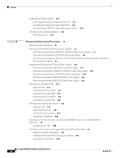
... the AC-Input PEM 4-78 Removing the DC-Input PEM 4-78 Installing the DC-Input PEM 4-80 Removing and Installing the Fan Tray 4-82 Required Tools 4-82 Removing the Fan Tray 4-83 Installing the Fan Assembly 4-92 Checking the Installation 4-92 Installing the Air Filter Assembly on a Catalyst 6509-NEB-A Switch or a Catalyst 6509-V-E (Optional...
... the AC-Input PEM 4-78 Removing the DC-Input PEM 4-78 Installing the DC-Input PEM 4-80 Removing and Installing the Fan Tray 4-82 Required Tools 4-82 Removing the Fan Tray 4-83 Installing the Fan Assembly 4-92 Checking the Installation 4-92 Installing the Air Filter Assembly on a Catalyst 6509-NEB-A Switch or a Catalyst 6509-V-E (Optional...
Installation Guide
Page 22
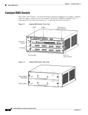
Catalyst 6503 Switch Chapter 1 Product Overview Catalyst 6503 Switch The Catalyst 6503 switch is NEBS L3 compliant. Figure 1-1 Catalyst 6503 Switch-Front View PEM 1 PEM 2 ESD ground strap connection 91239 Supervisor Engine Modules WS-SUP32-GE-3B STATUSSYSTEMACTIVE PWRMGMTRESET CATALYST 6500 SUPERVISOR ENGINE 32 CONSOLE WS-X6516-GE-T X 1 2 EJECT ... supporting redundant power supplies, redundant supervisor engines, and slots for up to bottom) Figure 1-2 Catalyst 6503 Switch-Rear View 63031 Power supply 2 (redundant) Power supply 1 INPUT FAN OUTPUT OK OK FAIL INPUT FAN OUTPUT...
Catalyst 6503 Switch Chapter 1 Product Overview Catalyst 6503 Switch The Catalyst 6503 switch is NEBS L3 compliant. Figure 1-1 Catalyst 6503 Switch-Front View PEM 1 PEM 2 ESD ground strap connection 91239 Supervisor Engine Modules WS-SUP32-GE-3B STATUSSYSTEMACTIVE PWRMGMTRESET CATALYST 6500 SUPERVISOR ENGINE 32 CONSOLE WS-X6516-GE-T X 1 2 EJECT ... supporting redundant power supplies, redundant supervisor engines, and slots for up to bottom) Figure 1-2 Catalyst 6503 Switch-Rear View 63031 Power supply 2 (redundant) Power supply 1 INPUT FAN OUTPUT OK OK FAIL INPUT FAN OUTPUT...
Installation Guide
Page 25
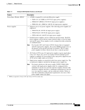
... one supervisor engine. The second power supply is required for 950 W AC-input power supplies). - Chapter 1 Product Overview Catalyst 6503 Switch Table 1-1 Catalyst 6503 Switch Features (continued) Feature Power Entry Module (PEM)1 Power supplies Description • A PEM is installed in the lower power supply bay. Power supplies can cause a false power supply output fail signal. 1. OL...
... one supervisor engine. The second power supply is required for 950 W AC-input power supplies). - Chapter 1 Product Overview Catalyst 6503 Switch Table 1-1 Catalyst 6503 Switch Features (continued) Feature Power Entry Module (PEM)1 Power supplies Description • A PEM is installed in the lower power supply bay. Power supplies can cause a false power supply output fail signal. 1. OL...
Installation Guide
Page 27
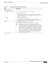
... 21.75 in. (17.78 x 44.12 x 55.25 cm). • Chassis requires 4 RU1. • The Catalyst 6503 switch chassis is designed to install in which the airflow is from front to fail. On Catalyst chassis in standard 19-inch equipment racks that meet ANSI/EIA 310-D, IEC 60297, and ETS 300...1 supervisor engine, 2 modules, 2 AC-input PEMs, and 2 AC-input power supplies: 85.4 lb (38.7 kg). • FAN-MOD-3 (Standard fan tray)-170 CFM • FAN-MOD-3HS (Optional high-speed fan tray)-270 CFM Note To maintain proper air circulation through the Catalyst switch chassis, we recommend that you maintain...
... 21.75 in. (17.78 x 44.12 x 55.25 cm). • Chassis requires 4 RU1. • The Catalyst 6503 switch chassis is designed to install in which the airflow is from front to fail. On Catalyst chassis in standard 19-inch equipment racks that meet ANSI/EIA 310-D, IEC 60297, and ETS 300...1 supervisor engine, 2 modules, 2 AC-input PEMs, and 2 AC-input power supplies: 85.4 lb (38.7 kg). • FAN-MOD-3 (Standard fan tray)-170 CFM • FAN-MOD-3HS (Optional high-speed fan tray)-270 CFM Note To maintain proper air circulation through the Catalyst switch chassis, we recommend that you maintain...
Installation Guide
Page 28
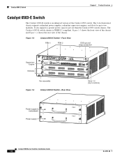
... OK OK FAIL INPUT FAN OUTPUT OK OK FAIL Catalyst 6500 Series Switches Installation Guide 1-8 OL-5781-08 Catalyst 6503-E Switch Chapter 1 Product Overview Catalyst 6503-E Switch The Catalyst 6503-E switch is NEBS L3 compliant. The Catalyst 6503-E switch chassis is an enhanced version of the chassis. Figure 1-3 Catalyst 6503-E Switch-Front View PEM 1 PEM 2 ESD ground strap connection 91239 Supervisor Engine Modules...
... OK OK FAIL INPUT FAN OUTPUT OK OK FAIL Catalyst 6500 Series Switches Installation Guide 1-8 OL-5781-08 Catalyst 6503-E Switch Chapter 1 Product Overview Catalyst 6503-E Switch The Catalyst 6503-E switch is NEBS L3 compliant. The Catalyst 6503-E switch chassis is an enhanced version of the chassis. Figure 1-3 Catalyst 6503-E Switch-Front View PEM 1 PEM 2 ESD ground strap connection 91239 Supervisor Engine Modules...
Installation Guide
Page 30
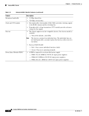
...power supplies). - you must replace the fan tray in the event of a fan failure. PEM-15A-AC (PEM for 1400 W AC-input power supplies). 1-10 Catalyst 6500 Series Switches Installation Guide OL-5781-08 WS-C6503-E-FAN-282 CFM Note The fan tray...or more individual fans have failed. - Green-Fan tray is operating normally. • A PEM is available: - PEM-DC/3 (PEM for each installed power supply. - Catalyst 6503-E Switch Chapter 1 Product Overview Table 1-3 Catalyst 6503-E Switch Features (continued) Feature Backplane bandwidth Clock and VTT module Fan tray Description • ...
...power supplies). - you must replace the fan tray in the event of a fan failure. PEM-15A-AC (PEM for 1400 W AC-input power supplies). 1-10 Catalyst 6500 Series Switches Installation Guide OL-5781-08 WS-C6503-E-FAN-282 CFM Note The fan tray...or more individual fans have failed. - Green-Fan tray is operating normally. • A PEM is available: - PEM-DC/3 (PEM for each installed power supply. - Catalyst 6503-E Switch Chapter 1 Product Overview Table 1-3 Catalyst 6503-E Switch Features (continued) Feature Backplane bandwidth Clock and VTT module Fan tray Description • ...
Installation Guide
Page 31
... air temperature sensors that are equipped with single power supplies must have a minimum configuration of the Catalyst 6503-E switch chassis. PEMs are supported: - PWR-950-DC (950 W DC-input power supply). - Failure to 55°C) Note The Catalyst 6500 series switches are triggered at 104°F (40°C) generating a minor alarm and at 131...
... air temperature sensors that are equipped with single power supplies must have a minimum configuration of the Catalyst 6503-E switch chassis. PEMs are supported: - PWR-950-DC (950 W DC-input power supply). - Failure to 55°C) Note The Catalyst 6500 series switches are triggered at 104°F (40°C) generating a minor alarm and at 131...
Installation Guide
Page 32
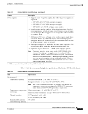
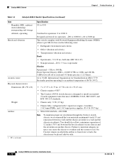
... switch complies with Network Equipment Building Systems (NEBS) (Zone 4 per axis (1.12 Grms). 64 to 76 dB. Catalyst 6503-E Switch Chapter 1 Product Overview Table 1-4 Catalyst 6503-E Switch Specifications (continued) Item Humidity (RH), ambient (noncondensing) nonoperating and storage Altitude, operating Shock and vibration Acoustic noise...with 1 supervisor engine, 2 modules, 2 AC-input PEMs, and 2 AC-input power supplies: 85.4 lb (38.7 kg). • WS-C6503-E-FAN-282 CFM Note To maintain proper air circulation through the Catalyst switch chassis, we recommend that you maintain a minimum ...
... switch complies with Network Equipment Building Systems (NEBS) (Zone 4 per axis (1.12 Grms). 64 to 76 dB. Catalyst 6503-E Switch Chapter 1 Product Overview Table 1-4 Catalyst 6503-E Switch Specifications (continued) Item Humidity (RH), ambient (noncondensing) nonoperating and storage Altitude, operating Shock and vibration Acoustic noise...with 1 supervisor engine, 2 modules, 2 AC-input PEMs, and 2 AC-input power supplies: 85.4 lb (38.7 kg). • WS-C6503-E-FAN-282 CFM Note To maintain proper air circulation through the Catalyst switch chassis, we recommend that you maintain a minimum ...
Installation Guide
Page 131
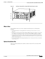
...information on page 3-52. • Installing and connecting the Power Entry Modules (PEMs) and the power supplies to Chapter 4 for either the Catalyst 6503 or the Catalyst 6503-E switch chassis. See "Attaching the Interface Cables" section on page 3-84. ...the chassis and verifying the installation. Go to source power. Chapter 3 Installing the Switch Installing a Catalyst 6503 or Catalyst 6503-E Switch Chassis Figure 3-3 Installing a Catalyst 6503 or Catalyst 6503-E Switch Chassis in a Rack 63181 WS-X6K-SUP2-2GE STATUS SYSTEMCONSOLPEWR MGRMETSET SUPERVISOR2 CONSOLE CONSOLE PORT...
...information on page 3-52. • Installing and connecting the Power Entry Modules (PEMs) and the power supplies to Chapter 4 for either the Catalyst 6503 or the Catalyst 6503-E switch chassis. See "Attaching the Interface Cables" section on page 3-84. ...the chassis and verifying the installation. Go to source power. Chapter 3 Installing the Switch Installing a Catalyst 6503 or Catalyst 6503-E Switch Chassis Figure 3-3 Installing a Catalyst 6503 or Catalyst 6503-E Switch Chassis in a Rack 63181 WS-X6K-SUP2-2GE STATUS SYSTEMCONSOLPEWR MGRMETSET SUPERVISOR2 CONSOLE CONSOLE PORT...
Installation Guide
Page 172
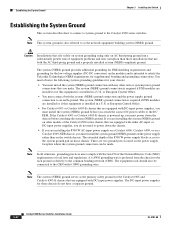
... ground) on the power supply rather than those chassis. The DC-input power supplies for supplemental bonding and grounding connections. If the Catalyst 6503 or Catalyst 6503-E chassis is installed in a U.S. or European Central Office. • You must comply with either AC-input or DC-input power... the modules and is also referred to satisfy the Telcordia Technologies NEBS requirements for these chassis do not need to the DC PEM. The system (NEBS) ground provides additional grounding for EMI shielding requirements and grounding for the low voltage supplies (DC-DC ...
... ground) on the power supply rather than those chassis. The DC-input power supplies for supplemental bonding and grounding connections. If the Catalyst 6503 or Catalyst 6503-E chassis is installed in a U.S. or European Central Office. • You must comply with either AC-input or DC-input power... the modules and is also referred to satisfy the Telcordia Technologies NEBS requirements for these chassis do not need to the DC PEM. The system (NEBS) ground provides additional grounding for EMI shielding requirements and grounding for the low voltage supplies (DC-DC ...
Installation Guide
Page 173
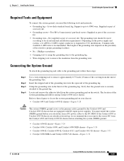
installations. Commercially available 6 AWG wire is securely attached to the DC PEM. Connecting the System Ground To attach the grounding lug and cable to the grounding pad, follow these figures to remove the insulation from the end... wire. Verify that the ground wire is recommended. Crimp the grounding wire in the barrel of the system grounding pad differs among Catalyst 6500 series chassis. If the Catalyst 6503 or Catalyst 6503-E chassis are equipped with DC-input power supplies. Supports up , we recommend that are already powered up to remove approximately 0.75 ...
installations. Commercially available 6 AWG wire is securely attached to the DC PEM. Connecting the System Ground To attach the grounding lug and cable to the grounding pad, follow these figures to remove the insulation from the end... wire. Verify that the ground wire is recommended. Crimp the grounding wire in the barrel of the system grounding pad differs among Catalyst 6500 series chassis. If the Catalyst 6503 or Catalyst 6503-E chassis are equipped with DC-input power supplies. Supports up , we recommend that are already powered up to remove approximately 0.75 ...
Installation Guide
Page 207
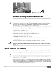
... module and scans the system for the Catalyst 6500 series field-replaceable units (FRUs): • Online Insertion and Removal, page 4-1 • Removing and Installing the AC-Input Power Supplies, page 4-2 • Removing and Installing the DC-Input Power Supplies, page 4-15 • Removing and Installing PEMs, page 4-75 • Removing and Installing...
... module and scans the system for the Catalyst 6500 series field-replaceable units (FRUs): • Online Insertion and Removal, page 4-1 • Removing and Installing the AC-Input Power Supplies, page 4-2 • Removing and Installing the DC-Input Power Supplies, page 4-15 • Removing and Installing PEMs, page 4-75 • Removing and Installing...
Installation Guide
Page 209
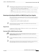
... "Removing and Installing PEMs" section on the power supply. Removing a 950 W or 1400 W AC-Input Power Supply Warning Hazardous voltage or energy is present on the backplane when the system is divided into the following power supply restrictions exist for the Catalyst 6503 and the Catalyst 6503-E switches. OL-5781-08 Catalyst 6500 Series Switches Installation...
... "Removing and Installing PEMs" section on the power supply. Removing a 950 W or 1400 W AC-Input Power Supply Warning Hazardous voltage or energy is present on the backplane when the system is divided into the following power supply restrictions exist for the Catalyst 6503 and the Catalyst 6503-E switches. OL-5781-08 Catalyst 6500 Series Switches Installation...

Installation Guide
Page 210
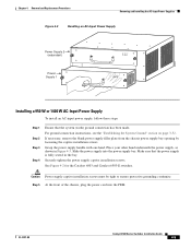
...Cisco part number 800-16727-01 for the Catalyst 6503 and 6503-E switches. Grasp the power supply handle with the captive installation screws. Do not touch the metal prongs embedded in Figure 4-3, and slide the power supply completely out of the chassis. Figure 4-1 Catalyst 6503 and Catalyst 6503-E Switches-PEM Location PEM 1 PEM... screws Catalyst 6500 Series Switches Installation Guide 4-4 63191 OL-5781-08 Remove the power cord from the power source. See Figure 4-2 for the Catalyst 6503 and Catalyst 6503-E switches) over the opening, and secure it is to the PEM.
...Cisco part number 800-16727-01 for the Catalyst 6503 and 6503-E switches. Grasp the power supply handle with the captive installation screws. Do not touch the metal prongs embedded in Figure 4-3, and slide the power supply completely out of the chassis. Figure 4-1 Catalyst 6503 and Catalyst 6503-E Switches-PEM Location PEM 1 PEM... screws Catalyst 6500 Series Switches Installation Guide 4-4 63191 OL-5781-08 Remove the power cord from the power source. See Figure 4-2 for the Catalyst 6503 and Catalyst 6503-E switches) over the opening, and secure it is to the PEM.
Installation Guide
Page 211
Securely tighten the power supply captive installation screws. OL-5781-08 Catalyst 6500 Series Switches Installation Guide 4-5 Place your other hand underneath the power supply, as shown in the bay. See Figure 4-2 for the Catalyst 6503 and Catalyst 6503-E switches. Grasp the power supply handle with one hand...filler plate from the chassis power supply bay opening by loosening the captive installation screws. Slide the power supply into the PEM. For ground connection instructions, see the "Establishing the System Ground" section on page 3-52. Caution Power supply captive ...
Securely tighten the power supply captive installation screws. OL-5781-08 Catalyst 6500 Series Switches Installation Guide 4-5 Place your other hand underneath the power supply, as shown in the bay. See Figure 4-2 for the Catalyst 6503 and Catalyst 6503-E switches. Grasp the power supply handle with one hand...filler plate from the chassis power supply bay opening by loosening the captive installation screws. Slide the power supply into the PEM. For ground connection instructions, see the "Establishing the System Ground" section on page 3-52. Caution Power supply captive ...
Installation Guide
Page 212
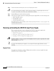
... Replacement Procedures Step 6 Connect the other end of a power source failure, the second source should still be available. Step 7 Step 8 Turn the PEM power switch to remove and install the 2700 W AC-input power supply in the following topics: • Required Tools, page 4-6 • Removing...FAIL LED is operating. Removing and Installing the 2700 W AC-Input Power Supply This section describes how to the On (|) position. Catalyst 6500 Series Switches Installation Guide 4-6 OL-5781-08 Caution In a system with redundant power supplies, you can replace the faulty supply ...
... Replacement Procedures Step 6 Connect the other end of a power source failure, the second source should still be available. Step 7 Step 8 Turn the PEM power switch to remove and install the 2700 W AC-input power supply in the following topics: • Required Tools, page 4-6 • Removing...FAIL LED is operating. Removing and Installing the 2700 W AC-Input Power Supply This section describes how to the On (|) position. Catalyst 6500 Series Switches Installation Guide 4-6 OL-5781-08 Caution In a system with redundant power supplies, you can replace the faulty supply ...

Installation Guide
Page 222
... removing (PEM 1 or PEM 2). Statement 322 Warning Hazardous voltage or energy is present on the backplane when the system is to remain empty, install a blank power supply filler plate (Cisco part number 800-16727-01) over the opening, and secure it with... the captive installation screws. Statement 1034 To remove a DC-input power supply, follow these chassis do not have a separate ground. Place your other hand underneath the power supply, as the primary safety ground for these steps: Step 1 Identify which PEM is removed from the DC circuits. Figure 4-8 Catalyst 6503...
... removing (PEM 1 or PEM 2). Statement 322 Warning Hazardous voltage or energy is present on the backplane when the system is to remain empty, install a blank power supply filler plate (Cisco part number 800-16727-01) over the opening, and secure it with... the captive installation screws. Statement 1034 To remove a DC-input power supply, follow these chassis do not have a separate ground. Place your other hand underneath the power supply, as the primary safety ground for these steps: Step 1 Identify which PEM is removed from the DC circuits. Figure 4-8 Catalyst 6503...
Installation Guide
Page 224
...the following procedures, ensure that power is removed from the circuit breaker switch handle, and restore power by ensuring that the chassis you are secure. Make sure that the power supply front panel LEDs are in Figure 4-10. As an added precaution, place the appropriate safety flag and... Catalyst 6503-E chassis that you are equipped with one hand. Grasp the power supply handle with DC-input power supplies. To ensure that all connections to the DC PEM for the power supply that are working on has the system (NEBS) ground installed. Turn OFF the DC power line circuit...
...the following procedures, ensure that power is removed from the circuit breaker switch handle, and restore power by ensuring that the chassis you are secure. Make sure that the power supply front panel LEDs are in Figure 4-10. As an added precaution, place the appropriate safety flag and... Catalyst 6503-E chassis that you are equipped with one hand. Grasp the power supply handle with DC-input power supplies. To ensure that all connections to the DC PEM for the power supply that are working on has the system (NEBS) ground installed. Turn OFF the DC power line circuit...
Installation Guide
Page 281
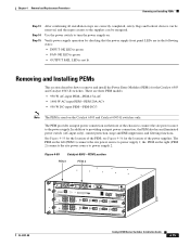
... switch (AC-input only), current protection, surge and EMI suppression, and filtering functions. Figure 4-55 Catalyst 6503-PEM Location PEM 1 PEM 2 OL-5781-08 63191 WS-X6K-SUP2-2GE STATUS SYSTEMCONSOLPEWR MGRMETSET SUPERVISOR2 CONSOLE CONSOLE PORT MODE PCMCIA EJECT...PEM-PEM-15A-AC • 1400 W AC-input PEM-PEM-20A-AC+ • 950 W DC-input PEM-PEM-DC/3 Note The PEM is not lit Removing and Installing PEMs This section describes how to remove and install the Power Entry Modules (PEMs) for the location of the PEM; See Figure 4-55 for the Catalyst 6503 and Catalyst 6503...
... switch (AC-input only), current protection, surge and EMI suppression, and filtering functions. Figure 4-55 Catalyst 6503-PEM Location PEM 1 PEM 2 OL-5781-08 63191 WS-X6K-SUP2-2GE STATUS SYSTEMCONSOLPEWR MGRMETSET SUPERVISOR2 CONSOLE CONSOLE PORT MODE PCMCIA EJECT...PEM-PEM-15A-AC • 1400 W AC-input PEM-PEM-20A-AC+ • 950 W DC-input PEM-PEM-DC/3 Note The PEM is not lit Removing and Installing PEMs This section describes how to remove and install the Power Entry Modules (PEMs) for the location of the PEM; See Figure 4-55 for the Catalyst 6503 and Catalyst 6503...

Installation Guide
Page 282
... switch to remain empty, install a blank PEM filler plate (Cisco part number 800-16719-01) over the opening, and secure it part of the way out of the chassis. Remove the power cord from the power source. Removing and Installing PEMs Chapter 4 Removal and Replacement Procedures Figure 4-56 Catalyst 6503 Switch-Power Supply Location 63031 Power...
... switch to remain empty, install a blank PEM filler plate (Cisco part number 800-16719-01) over the opening, and secure it part of the way out of the chassis. Remove the power cord from the power source. Removing and Installing PEMs Chapter 4 Removal and Replacement Procedures Figure 4-56 Catalyst 6503 Switch-Power Supply Location 63031 Power...