Installation Guide
Page 9
... W Power Supply AC Power Cords A-46 6000 W AC-Input and DC-Input Power Supplies A-46 6000 W Power Supply Specifications A-48 6000 W Power Supply AC Power Cords A-53 8700 W AC-Input Power Supply A-54 8700 W Power Supply Specifications A-55 Remote Power Cycling Feature A-60 8700 W Power Supply AC Power Cords A-62 AC Power Cord Illustrations A-63 Power Supply Redundancy A-73 Transceivers, Module Connectors, and Cable Specifications B-1 Pluggable Transceivers B-1 Catalyst...
... W Power Supply AC Power Cords A-46 6000 W AC-Input and DC-Input Power Supplies A-46 6000 W Power Supply Specifications A-48 6000 W Power Supply AC Power Cords A-53 8700 W AC-Input Power Supply A-54 8700 W Power Supply Specifications A-55 Remote Power Cycling Feature A-60 8700 W Power Supply AC Power Cords A-62 AC Power Cord Illustrations A-63 Power Supply Redundancy A-73 Transceivers, Module Connectors, and Cable Specifications B-1 Pluggable Transceivers B-1 Catalyst...
Installation Guide
Page 11
... Installation Describes things you need to install your site before installing the Catalyst 6500 series switch. Power Supply Specifications Provides illustrations and specification tables for removing and installing chassis Replacement Procedures components. Preparing for the supported AC power cords. OL-5781-08 Catalyst 6500 Series Switches Installation Guide xi Organization This publication is organized, and...
... Installation Describes things you need to install your site before installing the Catalyst 6500 series switch. Power Supply Specifications Provides illustrations and specification tables for removing and installing chassis Replacement Procedures components. Preparing for the supported AC power cords. OL-5781-08 Catalyst 6500 Series Switches Installation Guide xi Organization This publication is organized, and...

Installation Guide
Page 112
...problems are properly seated. Medium Best grounding practices must be followed as closely as possible. Note In all I/O cables and power cords are not anticipated, but installing a best practice grounding system is always recommended. The equipment rack should be followed as much ... installations. Site Requirements Chapter 2 Preparing for the future. This installation has a history of malfunction due to the module. 2-18 Catalyst 6500 Series Switches Installation Guide OL-5781-08 A 6 AWG grounding wire is not subject to natural environmental noise or man-made ...
...problems are properly seated. Medium Best grounding practices must be followed as closely as possible. Note In all I/O cables and power cords are not anticipated, but installing a best practice grounding system is always recommended. The equipment rack should be followed as much ... installations. Site Requirements Chapter 2 Preparing for the future. This installation has a history of malfunction due to the module. 2-18 Catalyst 6500 Series Switches Installation Guide OL-5781-08 A 6 AWG grounding wire is not subject to natural environmental noise or man-made ...

Installation Guide
Page 113
...Cisco Technical Assistance Center: - The product does not operate correctly when you are not sure of the type of power source indicated on electrical equipment, follow your power company for site modifications. You have been provided with one or more power cables with your chassis power supply that power is damaged. - OL-5781-08 Catalyst...usage instructions. • Install the product in your work area, such as damp floors, ungrounded power extension cables, frayed or damaged power cords, and missing safety grounds. • If an electrical accident occurs, proceed as follows: - ...
...Cisco Technical Assistance Center: - The product does not operate correctly when you are not sure of the type of power source indicated on electrical equipment, follow your power company for site modifications. You have been provided with one or more power cables with your chassis power supply that power is damaged. - OL-5781-08 Catalyst...usage instructions. • Install the product in your work area, such as damp floors, ungrounded power extension cables, frayed or damaged power cords, and missing safety grounds. • If an electrical accident occurs, proceed as follows: - ...

Installation Guide
Page 116
... operating with the Catalyst 6500 series switch power supplies which use power factor correction (PFC). The grounding conductors that use an uninterruptible power supply (UPS) to protect against power failures at the service equipment. Power Connection Guidelines for AC-Powered Systems This section .... The 1300 W, 1400 W, 2500 W, 2700 W, and 3000 W power supplies require a 20 A circuit. - The 4000 W power supply requires a 30 A circuit. - The 4000 W AC-input power supply power cords are using a 200/240 VAC power source in North America, the circuit must be protected by a two-...
... operating with the Catalyst 6500 series switch power supplies which use power factor correction (PFC). The grounding conductors that use an uninterruptible power supply (UPS) to protect against power failures at the service equipment. Power Connection Guidelines for AC-Powered Systems This section .... The 1300 W, 1400 W, 2500 W, 2700 W, and 3000 W power supplies require a 20 A circuit. - The 4000 W power supply requires a 30 A circuit. - The 4000 W AC-input power supply power cords are using a 200/240 VAC power source in North America, the circuit must be protected by a two-...

Installation Guide
Page 210
.... Disconnect the power cord from the power connection on the PEM for the Catalyst 6503 and 6503-E switches. Grasp the power supply handle with the captive installation screws. If the power supply bay is to remain empty, install a blank power supply filler plate (Cisco part number 800-16727-01 for the Catalyst 6503 and Catalyst 6503-E switches) over the opening, and secure it is still...
.... Disconnect the power cord from the power connection on the PEM for the Catalyst 6503 and 6503-E switches. Grasp the power supply handle with the captive installation screws. If the power supply bay is to remain empty, install a blank power supply filler plate (Cisco part number 800-16727-01 for the Catalyst 6503 and Catalyst 6503-E switches) over the opening, and secure it is still...
Installation Guide
Page 211
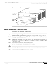
... the front of the chassis, plug the power cord into the power supply bay. Place your other hand underneath the power supply, as shown in the bay. Make sure that the system (earth) ground connection has been made. See Figure 4-2 for the Catalyst 6503 and Catalyst 6503-E switches. Grasp the power supply handle with one hand. For ground connection...
... the front of the chassis, plug the power cord into the power supply bay. Place your other hand underneath the power supply, as shown in the bay. Make sure that the system (earth) ground connection has been made. See Figure 4-2 for the Catalyst 6503 and Catalyst 6503-E switches. Grasp the power supply handle with one hand. For ground connection...
Installation Guide
Page 212
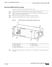
...should still be available. In case of the power cord to an AC-input power source. Removing and Installing the 2700 W AC-Input Power Supply This section describes how to the On (|) position. Use caution when servicing. Catalyst 6500 Series Switches Installation Guide 4-6 OL-5781-... 4-6 • Removing a 2700 W AC-Input Power Supply, page 4-7 • Installing a 2700 W AC-Input Power Supply, page 4-8 Warning Hazardous voltage or energy is operating. Verify the power supply operation by checking that the power supply LEDs are in the Catalyst 6504-E switch. Required Tools You might need a ...
...should still be available. In case of the power cord to an AC-input power source. Removing and Installing the 2700 W AC-Input Power Supply This section describes how to the On (|) position. Use caution when servicing. Catalyst 6500 Series Switches Installation Guide 4-6 OL-5781-... 4-6 • Removing a 2700 W AC-Input Power Supply, page 4-7 • Installing a 2700 W AC-Input Power Supply, page 4-8 Warning Hazardous voltage or energy is operating. Verify the power supply operation by checking that the power supply LEDs are in the Catalyst 6504-E switch. Required Tools You might need a ...
Installation Guide
Page 213
...-08 Catalyst 6500 Series Switches Installation Guide 4-7 Chapter 4 Removal and Replacement Procedures Removing and Installing the AC-Input Power Supplies Removing a 2700 W AC-Input Power Supply To remove a 2700 W AC-input power supply, follow these steps: Step 1 Step 2 Step 3 Step 4 Turn the power switch to the power supply. Disconnect the power cord from the power connection on the power cord while...
...-08 Catalyst 6500 Series Switches Installation Guide 4-7 Chapter 4 Removal and Replacement Procedures Removing and Installing the AC-Input Power Supplies Removing a 2700 W AC-Input Power Supply To remove a 2700 W AC-input power supply, follow these steps: Step 1 Step 2 Step 3 Step 4 Turn the power switch to the power supply. Disconnect the power cord from the power connection on the power cord while...
Installation Guide
Page 215
... than on (|) position. OL-5781-08 Catalyst 6500 Series Switches Installation Guide 4-9 Verify power supply operation by checking that support them. Chapter 4 Removal and Replacement Procedures Removing and Installing the AC-Input Power Supplies Step 6 Plug the power cord into the following states: • INPUT ...OK LED is green • FAN OK LED is green • OUTPUT FAIL LED is operating. Caution In a system with redundant power supplies, you to loosen ...
... than on (|) position. OL-5781-08 Catalyst 6500 Series Switches Installation Guide 4-9 Verify power supply operation by checking that support them. Chapter 4 Removal and Replacement Procedures Removing and Installing the AC-Input Power Supplies Step 6 Plug the power cord into the following states: • INPUT ...OK LED is green • FAN OK LED is green • OUTPUT FAIL LED is operating. Caution In a system with redundant power supplies, you to loosen ...
Installation Guide
Page 216
... the two M4 nuts securing the system ground lug to install and remove power supplies. Remove and set it aside. Catalyst 6500 series AC-input power supplies weigh between 14.5 pounds (6.58 kg) and 29.0 pounds (13.15 kg). 4-10 Catalyst 6500 Series Switches Installation Guide OL-5781-08 Disconnect the power cord from each post. b. Remove...
... the two M4 nuts securing the system ground lug to install and remove power supplies. Remove and set it aside. Catalyst 6500 series AC-input power supplies weigh between 14.5 pounds (6.58 kg) and 29.0 pounds (13.15 kg). 4-10 Catalyst 6500 Series Switches Installation Guide OL-5781-08 Disconnect the power cord from each post. b. Remove...
Installation Guide
Page 219
...4-6.) If you are installing an 8700 W power supply in the bay. Note The AC power cords for the 4000 W power supply are installing an 8700 W power supply in a Catalyst 6506, Catalyst 6509, or Catalyst 6509-NEB chassis, you are hard wired to the power supply. Chapter 4 Removal and Replacement Procedures ...see "Installing the System Ground on an 8700 W Power Supply" section on page 3-59 Plug the power cord into the power supply bay. Step 2 Step 3 Step 4 Step 5 Step 6 Step 7 Step 8 If necessary, remove the blank faceplate (Cisco part number 800-27924-xx) from its shipping packaging....
...4-6.) If you are installing an 8700 W power supply in the bay. Note The AC power cords for the 4000 W power supply are installing an 8700 W power supply in a Catalyst 6506, Catalyst 6509, or Catalyst 6509-NEB chassis, you are hard wired to the power supply. Chapter 4 Removal and Replacement Procedures ...see "Installing the System Ground on an 8700 W Power Supply" section on page 3-59 Plug the power cord into the power supply bay. Step 2 Step 3 Step 4 Step 5 Step 6 Step 7 Step 8 If necessary, remove the blank faceplate (Cisco part number 800-27924-xx) from its shipping packaging....

Installation Guide
Page 220
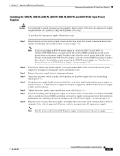
... a chassis with dual power supplies or power supplies with multiple AC inputs, connect each AC power cord to the on (|) position on page E-3 for each AC power cord. Only the LED for a power supply input that has an AC power cord attached will not power up. Turn the power switch to a separate ...input source. Removing and Installing the AC-Input Power Supplies Chapter 4 ...
... a chassis with dual power supplies or power supplies with multiple AC inputs, connect each AC power cord to the on (|) position on page E-3 for each AC power cord. Only the LED for a power supply input that has an AC power cord attached will not power up. Turn the power switch to a separate ...input source. Removing and Installing the AC-Input Power Supplies Chapter 4 ...

Installation Guide
Page 282
... (Cisco part number 800-16719-01) over the opening, and secure it part of the way out of the chassis. Remove the power cord from the power source. Place your other hand underneath the PEM, as shown in the PEM. Removing and Installing PEMs Chapter 4 Removal and Replacement Procedures Figure 4-56 Catalyst 6503 Switch-Power Supply Location 63031 Power...
... (Cisco part number 800-16719-01) over the opening, and secure it part of the way out of the chassis. Remove the power cord from the power source. Place your other hand underneath the PEM, as shown in the PEM. Removing and Installing PEMs Chapter 4 Removal and Replacement Procedures Figure 4-56 Catalyst 6503 Switch-Power Supply Location 63031 Power...
Installation Guide
Page 284
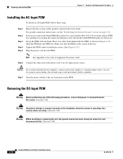
...necessary, remove the blank PEM filler plate (Cisco part number 800-16719-01) from the DC circuit. Slide the PEM into the PEM. Note See Appendix A for future use. Removing the DC-Input PEM Warning Before performing any of a power source failure, the second source will most ...52. Tighten the PEM captive installation screws. (See Figure 4-57.) Plug the power cord into the PEM bay. Statement 1046 4-78 Catalyst 6500 Series Switches Installation Guide OL-5781-08 Place your other end of supported AC power cords. Caution In a system with one hand. Step 6 Connect the other hand ...
...necessary, remove the blank PEM filler plate (Cisco part number 800-16719-01) from the DC circuit. Slide the PEM into the PEM. Note See Appendix A for future use. Removing the DC-Input PEM Warning Before performing any of a power source failure, the second source will most ...52. Tighten the PEM captive installation screws. (See Figure 4-57.) Plug the power cord into the PEM bay. Statement 1046 4-78 Catalyst 6500 Series Switches Installation Guide OL-5781-08 Place your other end of supported AC power cords. Caution In a system with one hand. Step 6 Connect the other hand ...
Installation Guide
Page 309
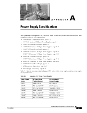
...; 8700 W AC-Input Power Supply, page A-54 • AC Power Cord Illustrations, page A-63 • Power Supply Redundancy, page A-73 Table A-1 lists the currently available Catalyst 6500 series switch power supplies and the power supply description location. A A P P E N D I X Power Supply Specifications This appendix describes the Catalyst 6500 series power supplies and provides their specifications. Table A-1 Catalyst 6500 Series Power Supplies Power Supply Rating 950...
...; 8700 W AC-Input Power Supply, page A-54 • AC Power Cord Illustrations, page A-63 • Power Supply Redundancy, page A-73 Table A-1 lists the currently available Catalyst 6500 series switch power supplies and the power supply description location. A A P P E N D I X Power Supply Specifications This appendix describes the Catalyst 6500 series power supplies and provides their specifications. Table A-1 Catalyst 6500 Series Power Supplies Power Supply Rating 950...
Installation Guide
Page 315
...in the same chassis, which means that power cord 1 can be plugged into phase A and power cord 2 can be plugged into phase B. Appendix A Power Supply Specifications 950 W AC-Input and DC-Input Power Supplies Table A-3 950 W AC-Input Power Supply Specifications (continued) Specification Description Branch circuit... A • For International-Circuits sized to local and national codes • All Catalyst 6500 series AC-input power supplies require single-phase source AC. • All AC power supply inputs are equipped with the hot conductor wired to a source AC phase and the...
...in the same chassis, which means that power cord 1 can be plugged into phase A and power cord 2 can be plugged into phase B. Appendix A Power Supply Specifications 950 W AC-Input and DC-Input Power Supplies Table A-3 950 W AC-Input Power Supply Specifications (continued) Specification Description Branch circuit... A • For International-Circuits sized to local and national codes • All Catalyst 6500 series AC-input power supplies require single-phase source AC. • All AC power supply inputs are equipped with the hot conductor wired to a source AC phase and the...
Installation Guide
Page 317
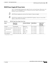
... 10 A, 250 VAC 10 A, 250 VAC 10 A, 250 VAC 10 A, 250 VAC 15 A, 125 VAC 10 A, 250 VAC Power Cord Reference Illustration Figure A-25 Figure A-20 Figure A-21 Figure A-22 Figure A-23 Figure A-24 OL-5781-08 Catalyst 6500 Series Switches Installation Guide A-9 Note All 950 W power supply power cords are 8 feet 2 inches (2.5 meters) in length.
... 10 A, 250 VAC 10 A, 250 VAC 10 A, 250 VAC 10 A, 250 VAC 15 A, 125 VAC 10 A, 250 VAC Power Cord Reference Illustration Figure A-25 Figure A-20 Figure A-21 Figure A-22 Figure A-23 Figure A-24 OL-5781-08 Catalyst 6500 Series Switches Installation Guide A-9 Note All 950 W power supply power cords are 8 feet 2 inches (2.5 meters) in length.
Installation Guide
Page 319
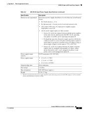
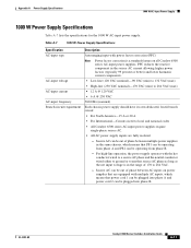
...AC can be out of phase between multiple power supplies in the same chassis, which means that power cord 1 can be plugged into phase A and power cord 2 can be operating from phase A and PS2 can be plugged into phase B. Table A-7 1000 W Power Supply Specifications Specification AC-input type AC-input ...A or 20 A • For International-Circuits sized to local and national codes • All Catalyst 6500 series AC-input power supplies require single-phase source AC. • All AC power supply inputs are equipped with the hot conductor wired to a source AC phase and the neutral conductor...
...AC can be out of phase between multiple power supplies in the same chassis, which means that power cord 1 can be plugged into phase A and power cord 2 can be operating from phase A and PS2 can be plugged into phase B. Table A-7 1000 W Power Supply Specifications Specification AC-input type AC-input ...A or 20 A • For International-Circuits sized to local and national codes • All Catalyst 6500 series AC-input power supplies require single-phase source AC. • All AC power supply inputs are equipped with the hot conductor wired to a source AC phase and the neutral conductor...
Installation Guide
Page 321
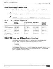
... references to power cord illustrations. Note All 1000 W power supply power cords are 8 feet 2 inches (2.5 meters) in the following Catalyst 6500 series switches: • Catalyst 6506 • Catalyst 6509 • Catalyst 6509-NEB The 1300 W power supply (see Figure A-5 for the 1300 W AC-input power supply and Figure A-6 for the 1000 W AC-input power supply. Table A-9 Locale 1000 W AC-Input Power Supply Power Cords Power Cord Part...
... references to power cord illustrations. Note All 1000 W power supply power cords are 8 feet 2 inches (2.5 meters) in the following Catalyst 6500 series switches: • Catalyst 6506 • Catalyst 6509 • Catalyst 6509-NEB The 1300 W power supply (see Figure A-5 for the 1300 W AC-input power supply and Figure A-6 for the 1000 W AC-input power supply. Table A-9 Locale 1000 W AC-Input Power Supply Power Cords Power Cord Part...
