Installation Guide
Page 8
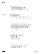
Contents 4 C H A P T E R Attaching the Interface Cables 3-61 Connecting the Supervisor Engine Console Port 3-61 Connecting the Supervisor Engine Uplink Ports 3-63 Using the Catalyst 6509-V-E Cable Management System 3-78 Verifying Switch Chassis Installation 3-84 Online Diagnostics 3-84 Removal and Replacement ...the Fan Tray 4-83 Installing the Fan Assembly 4-92 Checking the Installation 4-92 Installing the Air Filter Assembly on a Catalyst 6509-NEB-A Switch or a Catalyst 6509-V-E (Optional) 4-93 Checking the Air Filter 4-98 Installing the Remote Power Cycling Feature Control Wires (Optional) ...
Contents 4 C H A P T E R Attaching the Interface Cables 3-61 Connecting the Supervisor Engine Console Port 3-61 Connecting the Supervisor Engine Uplink Ports 3-63 Using the Catalyst 6509-V-E Cable Management System 3-78 Verifying Switch Chassis Installation 3-84 Online Diagnostics 3-84 Removal and Replacement ...the Fan Tray 4-83 Installing the Fan Assembly 4-92 Checking the Installation 4-92 Installing the Air Filter Assembly on a Catalyst 6509-NEB-A Switch or a Catalyst 6509-V-E (Optional) 4-93 Checking the Air Filter 4-98 Installing the Remote Power Cycling Feature Control Wires (Optional) ...
Installation Guide
Page 21
..., page 1-67 Note The Catalyst 6000 series switches (Catalyst 6006 switch and Catalyst 6009 switch) are described in a separate publication, the Catalyst 6000 Series Switches Installation Guide. Note Throughout this publication, except where noted, the term supervisor engine is used to refer to Supervisor Engine 2, Supervisor Engine 32, Supervisor Engine 32 PISA, Supervisor Engine 720, and Supervisor Engine 720-10GE.
..., page 1-67 Note The Catalyst 6000 series switches (Catalyst 6006 switch and Catalyst 6009 switch) are described in a separate publication, the Catalyst 6000 Series Switches Installation Guide. Note Throughout this publication, except where noted, the term supervisor engine is used to refer to Supervisor Engine 2, Supervisor Engine 32, Supervisor Engine 32 PISA, Supervisor Engine 720, and Supervisor Engine 720-10GE.
Installation Guide
Page 22
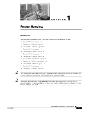
... and Figure 1-2 shows the rear view of the chassis. Figure 1-1 Catalyst 6503 Switch-Front View PEM 1 PEM 2 ESD ground strap connection 91239 Supervisor Engine Modules WS-SUP32-GE-3B STATUSSYSTEMACTIVE PWRMGMTRESET CATALYST 6500 SUPERVISOR ENGINE 32 CONSOLE WS-X6516-GE-T X 1 2 EJECT 3 4 DISK...top to two modules. The chassis is a 3-slot horizontal chassis supporting redundant power supplies, redundant supervisor engines, and slots for up to bottom) Figure 1-2 Catalyst 6503 Switch-Rear View 63031 Power supply 2 (redundant) Power supply 1 INPUT FAN OUTPUT OK OK FAIL...
... and Figure 1-2 shows the rear view of the chassis. Figure 1-1 Catalyst 6503 Switch-Front View PEM 1 PEM 2 ESD ground strap connection 91239 Supervisor Engine Modules WS-SUP32-GE-3B STATUSSYSTEMACTIVE PWRMGMTRESET CATALYST 6500 SUPERVISOR ENGINE 32 CONSOLE WS-X6516-GE-T X 1 2 EJECT 3 4 DISK...top to two modules. The chassis is a 3-slot horizontal chassis supporting redundant power supplies, redundant supervisor engines, and slots for up to bottom) Figure 1-2 Catalyst 6503 Switch-Rear View 63031 Power supply 2 (redundant) Power supply 1 INPUT FAN OUTPUT OK OK FAIL...

Installation Guide
Page 23
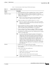
... connections. • Supports up to support the supervisor engines. • Supervisor engines can be installed. Chapter 1 Product Overview Catalyst 6503 Switch Table 1-1 lists the features of the switch. Table 1-1 Catalyst 6503 Switch Features Feature Chassis Supervisor engine Description • Three horizontal slots. Note In systems with redundant supervisor engines, both supervisor engines must have the same daughter card configurations...
... connections. • Supports up to support the supervisor engines. • Supervisor engines can be installed. Chapter 1 Product Overview Catalyst 6503 Switch Table 1-1 lists the features of the switch. Table 1-1 Catalyst 6503 Switch Features Feature Chassis Supervisor engine Description • Three horizontal slots. Note In systems with redundant supervisor engines, both supervisor engines must have the same daughter card configurations...
Installation Guide
Page 24
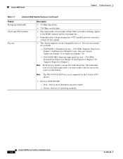
... to the EOBC channel and the switching bus. • Nonreplaceable voltage termination (VTT) module provides reference voltage for Supervisor Engine 32 and Supervisor Engine 720. Supports Supervisor Engine 2. you must replace the fan tray in the Catalyst 6503 chassis. • Fan tray STATUS LED - The individual fans are available: - Note The WS-C6503-E-FAN tray...
... to the EOBC channel and the switching bus. • Nonreplaceable voltage termination (VTT) module provides reference voltage for Supervisor Engine 32 and Supervisor Engine 720. Supports Supervisor Engine 2. you must replace the fan tray in the Catalyst 6503 chassis. • Fan tray STATUS LED - The individual fans are available: - Note The WS-C6503-E-FAN tray...
Installation Guide
Page 25
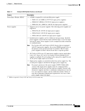
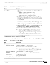
... - PWR-950-AC (950 W AC-input power supply). - Power supplies can be of one fan tray, one supervisor engine, and one supervisor engine. Source AC can be both AC-input, both DC-input, or one AC-input and one or two power supplies...PEM for 950 W AC-input power supplies). - PEM-20A-AC+ (PEM for Catalyst 6503 and Catalyst 6503-E switches only. The DC-input power supplies for each installed power supply. - Chapter 1 Product Overview Catalyst 6503 Switch Table 1-1 Catalyst 6503 Switch Features (continued) Feature Power Entry Module (PEM)1 Power supplies Description • ...
... - PWR-950-AC (950 W AC-input power supply). - Power supplies can be of one fan tray, one supervisor engine, and one supervisor engine. Source AC can be both AC-input, both DC-input, or one AC-input and one or two power supplies...PEM for 950 W AC-input power supplies). - PEM-20A-AC+ (PEM for Catalyst 6503 and Catalyst 6503-E switches only. The DC-input power supplies for each installed power supply. - Chapter 1 Product Overview Catalyst 6503 Switch Table 1-1 Catalyst 6503 Switch Features (continued) Feature Power Entry Module (PEM)1 Power supplies Description • ...
Installation Guide
Page 27
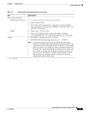
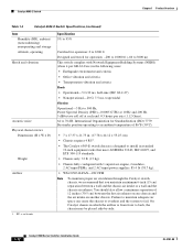
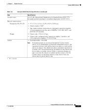
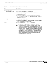
.... (17.78 x 44.12 x 55.25 cm). • Chassis requires 4 RU1. • The Catalyst 6503 switch chassis is from front to fail. Chapter 1 Product Overview Catalyst 6503 Switch Table 1-2 Catalyst 6503 Switch Specifications (continued) Item Physical Characteristics Dimensions (H x W x D) Weight Airflow 1. Failure to maintain adequate air... 310-D, IEC 60297, and ETS 300-119 standards. • Chassis only: 27 lb (12.25 kg). • Chassis fully configured with 1 supervisor engine, 2 modules, 2 AC-input PEMs, and 2 AC-input power supplies: 85.4 lb (38.7 kg). • FAN-MOD-3 (Standard...
.... (17.78 x 44.12 x 55.25 cm). • Chassis requires 4 RU1. • The Catalyst 6503 switch chassis is from front to fail. Chapter 1 Product Overview Catalyst 6503 Switch Table 1-2 Catalyst 6503 Switch Specifications (continued) Item Physical Characteristics Dimensions (H x W x D) Weight Airflow 1. Failure to maintain adequate air... 310-D, IEC 60297, and ETS 300-119 standards. • Chassis only: 27 lb (12.25 kg). • Chassis fully configured with 1 supervisor engine, 2 modules, 2 AC-input PEMs, and 2 AC-input power supplies: 85.4 lb (38.7 kg). • FAN-MOD-3 (Standard...
Installation Guide
Page 28
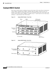
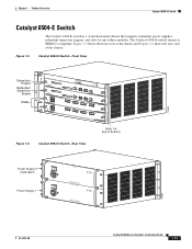
... the chassis and Figure 1-4 shows the rear view of the Catalyst 6503 switch. It also supports a greater power capacity per slot than the Catalyst 6503 switch chassis. The 3-slot horizontal chassis supports redundant power supplies, redundant supervisor engines, and slots for up to bottom) Figure 1-4 Catalyst 6503-E Switch-Rear View 63031 Power supply 2 (redundant) Power supply 1 INPUT...
... the chassis and Figure 1-4 shows the rear view of the Catalyst 6503 switch. It also supports a greater power capacity per slot than the Catalyst 6503 switch chassis. The 3-slot horizontal chassis supports redundant power supplies, redundant supervisor engines, and slots for up to bottom) Figure 1-4 Catalyst 6503-E Switch-Rear View 63031 Power supply 2 (redundant) Power supply 1 INPUT...
Installation Guide
Page 29
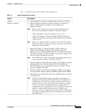
... same model and have a built-in standby mode. OL-5781-08 Catalyst 6500 Series Switches Installation Guide 1-9 Table 1-3 Catalyst 6503-E Switch Features Feature Chassis Supervisor engine Description • Three horizontal slots. Check your software release notes for modules. ...Each supervisor engine must have its own, which means that you install a certain supervisor engine - Require a specific software release level to run the configured features of the Catalyst 6503-E switch chassis. Have chassis slot restrictions -...
... same model and have a built-in standby mode. OL-5781-08 Catalyst 6500 Series Switches Installation Guide 1-9 Table 1-3 Catalyst 6503-E Switch Features Feature Chassis Supervisor engine Description • Three horizontal slots. Check your software release notes for modules. ...Each supervisor engine must have its own, which means that you install a certain supervisor engine - Require a specific software release level to run the configured features of the Catalyst 6503-E switch chassis. Have chassis slot restrictions -...
Installation Guide
Page 31
... unpackaged: -4° to 149°F (-20° to 65°C) Chassis in the upper power supply bay. • Supervisor Engine 2T requires a 1400 W power supply to meet these minimum configuration requirements can be configured in the lower power supply bay...for operation: 32° to 104°F (0° to 40°C) Designed and tested for Catalyst 6503 and Catalyst 6503-E switches only. Chapter 1 Product Overview Catalyst 6503-E Switch Table 1-3 Catalyst 6503-E Switch Features (continued) Feature Description Power supplies • Supports one additional module. The second ...
... unpackaged: -4° to 149°F (-20° to 65°C) Chassis in the upper power supply bay. • Supervisor Engine 2T requires a 1400 W power supply to meet these minimum configuration requirements can be configured in the lower power supply bay...for operation: 32° to 104°F (0° to 40°C) Designed and tested for Catalyst 6503 and Catalyst 6503-E switches only. Chapter 1 Product Overview Catalyst 6503-E Switch Table 1-3 Catalyst 6503-E Switch Features (continued) Feature Description Power supplies • Supports one additional module. The second ...
Installation Guide
Page 32
... may be placed side-by-side. 1-12 Catalyst 6500 Series Switches Installation Guide OL-5781-08 International Organization for operation: -200 to 10000 ft (-60 to 3000 m) This switch complies with 1 supervisor engine, 2 modules, 2 AC-input PEMs,... Chassis fully configured with Network Equipment Building Systems (NEBS) (Zone 4 per axis (1.12 Grms). 64 to fail. Catalyst 6503-E Switch Chapter 1 Product Overview Table 1-4 Catalyst 6503-E Switch Specifications (continued) Item Humidity (RH), ambient (noncondensing) nonoperating and storage Altitude, operating Shock and vibration Acoustic ...
... may be placed side-by-side. 1-12 Catalyst 6500 Series Switches Installation Guide OL-5781-08 International Organization for operation: -200 to 10000 ft (-60 to 3000 m) This switch complies with 1 supervisor engine, 2 modules, 2 AC-input PEMs,... Chassis fully configured with Network Equipment Building Systems (NEBS) (Zone 4 per axis (1.12 Grms). 64 to fail. Catalyst 6503-E Switch Chapter 1 Product Overview Table 1-4 Catalyst 6503-E Switch Specifications (continued) Item Humidity (RH), ambient (noncondensing) nonoperating and storage Altitude, operating Shock and vibration Acoustic ...
Installation Guide
Page 33
... Switches Installation Guide 1-13 Chapter 1 Product Overview Catalyst 6504-E Switch Catalyst 6504-E Switch The Catalyst 6504-E switch is NEBS L3 compliant. Figure 1-5 shows the front view of the chassis and Figure 1-6 shows the rear view of the chassis. Figure 1-5 Catalyst 6504-E Switch-Front View 126559 Supervisor Engine Redundant Supervisor Engine OSMs FAN STATUS STATUS STATUS Figure...
... Switches Installation Guide 1-13 Chapter 1 Product Overview Catalyst 6504-E Switch Catalyst 6504-E Switch The Catalyst 6504-E switch is NEBS L3 compliant. Figure 1-5 shows the front view of the chassis and Figure 1-6 shows the rear view of the chassis. Figure 1-5 Catalyst 6504-E Switch-Front View 126559 Supervisor Engine Redundant Supervisor Engine OSMs FAN STATUS STATUS STATUS Figure...

Installation Guide
Page 34
... and WS-X6500-SFM2 Switch Fabric Modules. • Some Catalyst 6500 series modules may: - Modules Backplane bandwidth • Supervisor Engine 720, Supervisor Engine 720-10GE, and Supervisor Engine 2T have a built-in slot 1 and slot 2. Each supervisor engine must have its own, which means that all supervisor engine resources are installed in switching fabric. Additionally, each...
... and WS-X6500-SFM2 Switch Fabric Modules. • Some Catalyst 6500 series modules may: - Modules Backplane bandwidth • Supervisor Engine 720, Supervisor Engine 720-10GE, and Supervisor Engine 2T have a built-in slot 1 and slot 2. Each supervisor engine must have its own, which means that all supervisor engine resources are installed in switching fabric. Additionally, each...
Installation Guide
Page 35
... can be configured in the lower power supply bay. Systems with a minimum of one fan tray, one supervisor engine, and one hot-swappable fan tray. OL-5781-08 Catalyst 6500 Series Switches Installation Guide 1-15 Green-Fan tray is available: - The second power supply is installed ... W DC-input power supply). • Installed power supplies can be both AC-input, both DC-input, or one AC-input and one supervisor engine. Failure to the EOBC channel and the switching bus. • Nonreplaceable voltage termination (VTT) module provides reference voltage for bus signals. ...
... can be configured in the lower power supply bay. Systems with a minimum of one fan tray, one supervisor engine, and one hot-swappable fan tray. OL-5781-08 Catalyst 6500 Series Switches Installation Guide 1-15 Green-Fan tray is available: - The second power supply is installed ... W DC-input power supply). • Installed power supplies can be both AC-input, both DC-input, or one AC-input and one supervisor engine. Failure to the EOBC channel and the switching bus. • Nonreplaceable voltage termination (VTT) module provides reference voltage for bus signals. ...
Installation Guide
Page 37
... minimum separation of 86°F (30°C). • 8.7 x 17.5 x 21.6 in. (22.09 x 44.45 x 54.86 cm). • Chassis requires 5 RU1. • The Catalyst 6504-E switch chassis is from front to install in which the airflow is designed to back, the chassis may be placed side-by-side. Chapter...meet ANSI/EIA 310-D, IEC 60297, and ETS 300-119 standards. • Chassis only: 27 lb (12.25 kg). • Chassis fully configured with 2 supervisor engines, 2 modules, and 2 AC-input power supplies: 97 lb (43.99 kg). • FAN-MOD-4HS-300 CFM Note To maintain proper air circulation through...
... minimum separation of 86°F (30°C). • 8.7 x 17.5 x 21.6 in. (22.09 x 44.45 x 54.86 cm). • Chassis requires 5 RU1. • The Catalyst 6504-E switch chassis is from front to install in which the airflow is designed to back, the chassis may be placed side-by-side. Chapter...meet ANSI/EIA 310-D, IEC 60297, and ETS 300-119 standards. • Chassis only: 27 lb (12.25 kg). • Chassis fully configured with 2 supervisor engines, 2 modules, and 2 AC-input power supplies: 97 lb (43.99 kg). • FAN-MOD-4HS-300 CFM Note To maintain proper air circulation through...

Installation Guide
Page 38
...-X6408 1 2 3 STATUS 8 PORT GIGABIT ETHERNET LINK LINK WS-X6408 1 2 3 STATUS 8 PORT GIGABIT ETHERNET LINK WS-SUP32-GE-3B STATUSSYSTEMACTIVE PWRMGMTRESET CATALYST 6500 SUPERVISOR ENGINE 32 CONSOLE WS-SUP32-GE-3B STATUSSYSTEMACTIVE PWRMGMTRESET CATALYST 6500 SUPERVISOR ENGINE 32 CONSOLE LINK DISK 0 EJECT DISK 0 EJECT LINK LINK LINK LINK LINK 4 5 6 LINK LINK 4 5 6 LINK LINK 4 5 6 LINK LINK...
...-X6408 1 2 3 STATUS 8 PORT GIGABIT ETHERNET LINK LINK WS-X6408 1 2 3 STATUS 8 PORT GIGABIT ETHERNET LINK WS-SUP32-GE-3B STATUSSYSTEMACTIVE PWRMGMTRESET CATALYST 6500 SUPERVISOR ENGINE 32 CONSOLE WS-SUP32-GE-3B STATUSSYSTEMACTIVE PWRMGMTRESET CATALYST 6500 SUPERVISOR ENGINE 32 CONSOLE LINK DISK 0 EJECT DISK 0 EJECT LINK LINK LINK LINK LINK 4 5 6 LINK LINK 4 5 6 LINK LINK 4 5 6 LINK LINK...
Installation Guide
Page 39
... all require the high-speed fan tray (WS-C6K-6SLOT-FAN2) be used for modules. You must have the resources to support the supervisor engines. - OL-5781-08 Catalyst 6500 Series Switches Installation Guide 1-19 Note Refer to your software release notes for the minimum software release versions required to run the...
... all require the high-speed fan tray (WS-C6K-6SLOT-FAN2) be used for modules. You must have the resources to support the supervisor engines. - OL-5781-08 Catalyst 6500 Series Switches Installation Guide 1-19 Note Refer to your software release notes for the minimum software release versions required to run the...
Installation Guide
Page 40
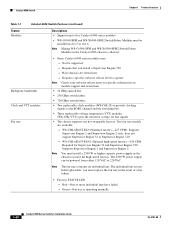
... you must replace the fan tray in the Catalyst 6506 chassis is operating normally. 1-20 Catalyst 6500 Series Switches Installation Guide OL-5781-08 you install a Supervisor Engine 720 - Red-One or more individual fans have failed. - Supports Supervisor Engine 1 and Supervisor Engine 2 only; Supports Supervisor Engine 1 and Supervisor Engine 2. Note The fan trays contains six individual...
... you must replace the fan tray in the Catalyst 6506 chassis is operating normally. 1-20 Catalyst 6500 Series Switches Installation Guide OL-5781-08 you install a Supervisor Engine 720 - Red-One or more individual fans have failed. - Supports Supervisor Engine 1 and Supervisor Engine 2 only; Supports Supervisor Engine 1 and Supervisor Engine 2. Note The fan trays contains six individual...

Installation Guide
Page 41
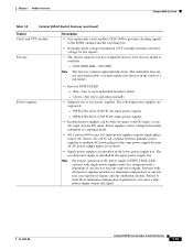
...minimum configuration requirements can be configured with single power supplies must install a 2500 W or higher capacity power supply when using the Supervisor Engine 32 or the Supervisor Engine 720 and the high-speed fan tray. Failure to 4000 W maximum output when installed in the right power supply bay...are supported: - WS-CAC-3000W (3000 W AC-input power supply). - WS-CAC-4000W-US (4000 W AC-input power supply). - OL-5781-08 Catalyst 6500 Series Switches Installation Guide 1-21 WS-CAC-2500W (2500 W AC-input power supply). - WS-CAC-4000W-INT (4000 W AC-input power supply). -...
...minimum configuration requirements can be configured with single power supplies must install a 2500 W or higher capacity power supply when using the Supervisor Engine 32 or the Supervisor Engine 720 and the high-speed fan tray. Failure to 4000 W maximum output when installed in the right power supply bay...are supported: - WS-CAC-3000W (3000 W AC-input power supply). - WS-CAC-4000W-US (4000 W AC-input power supply). - OL-5781-08 Catalyst 6500 Series Switches Installation Guide 1-21 WS-CAC-2500W (2500 W AC-input power supply). - WS-CAC-4000W-INT (4000 W AC-input power supply). -...
Installation Guide
Page 43
... Series Switches Installation Guide 1-23 WS-C6K-6SLOT-FAN2 (Optional high-speed fan tray)-420 CFM. Note To maintain proper air circulation through the Catalyst switch chassis, we recommend that meet ANSI/EIA 310-D, IEC 60297, and ETS 300-119 standards. • Chassis only: 45 lb (20.4 kg). &#...8226; Chassis fully configured with 1 supervisor engine, 5 switching modules, and 2 power supplies: 156.6 lb (71.0 kg). Failure to maintain adequate air space can cause the chassis to overheat and the ...
... Series Switches Installation Guide 1-23 WS-C6K-6SLOT-FAN2 (Optional high-speed fan tray)-420 CFM. Note To maintain proper air circulation through the Catalyst switch chassis, we recommend that meet ANSI/EIA 310-D, IEC 60297, and ETS 300-119 standards. • Chassis only: 45 lb (20.4 kg). &#...8226; Chassis fully configured with 1 supervisor engine, 5 switching modules, and 2 power supplies: 156.6 lb (71.0 kg). Failure to maintain adequate air space can cause the chassis to overheat and the ...