Installation Guide
Page 5
... iii-xii Statement 1071-Warning Definition xiv Related Documentation xix Product Overview 1-1 Catalyst 6503 Switch 1-2 Catalyst 6503-E Switch 1-8 Catalyst 6504-E Switch 1-13 Catalyst 6506 Switch 1-18 Catalyst 6506-E Switch 1-24 Catalyst 6509 Switch 1-30 Catalyst 6509-E Switch 1-36 Catalyst 6509-NEB Switch 1-42 Catalyst 6509-NEB-A Switch 1-49 Catalyst 6509-V-E Switch 1-55 Catalyst 6513 Switch 1-61 Catalyst 6513-E Switch 1-67 Preparing for Installation 2-1 Safety 2-2 Site Requirements 2-2 Temperature 2-3 Air Flow...
... iii-xii Statement 1071-Warning Definition xiv Related Documentation xix Product Overview 1-1 Catalyst 6503 Switch 1-2 Catalyst 6503-E Switch 1-8 Catalyst 6504-E Switch 1-13 Catalyst 6506 Switch 1-18 Catalyst 6506-E Switch 1-24 Catalyst 6509 Switch 1-30 Catalyst 6509-E Switch 1-36 Catalyst 6509-NEB Switch 1-42 Catalyst 6509-NEB-A Switch 1-49 Catalyst 6509-V-E Switch 1-55 Catalyst 6513 Switch 1-61 Catalyst 6513-E Switch 1-67 Preparing for Installation 2-1 Safety 2-2 Site Requirements 2-2 Temperature 2-3 Air Flow...
Installation Guide
Page 7
OL-5781-08 Contents Installing a Catalyst 6509 or Catalyst 6509-E Switch Chassis 3-21 Installation Accessory Kits 3-21 L Brackets on the Catalyst 6509 and Catalyst 6509-E Switches 3-21 Installing the 3 RU Rack-Mount Shelf Kit 3-22 Rack-Mounting the Chassis 3-23 What is Next 3-25 Optional Installation Kits 3-25 Installing a Catalyst 6509-NEB or Catalyst 6509-NEB-A Switch Chassis 3-26 Installation Accessory Kits 3-26...
OL-5781-08 Contents Installing a Catalyst 6509 or Catalyst 6509-E Switch Chassis 3-21 Installation Accessory Kits 3-21 L Brackets on the Catalyst 6509 and Catalyst 6509-E Switches 3-21 Installing the 3 RU Rack-Mount Shelf Kit 3-22 Rack-Mounting the Chassis 3-23 What is Next 3-25 Optional Installation Kits 3-25 Installing a Catalyst 6509-NEB or Catalyst 6509-NEB-A Switch Chassis 3-26 Installation Accessory Kits 3-26...
Installation Guide
Page 8
...Attaching the Interface Cables 3-61 Connecting the Supervisor Engine Console Port 3-61 Connecting the Supervisor Engine Uplink Ports 3-63 Using the Catalyst 6509-V-E Cable Management System 3-78 Verifying Switch Chassis Installation 3-84 Online Diagnostics 3-84 Removal and Replacement Procedures 4-1 Online Insertion and ... Tray 4-83 Installing the Fan Assembly 4-92 Checking the Installation 4-92 Installing the Air Filter Assembly on a Catalyst 6509-NEB-A Switch or a Catalyst 6509-V-E (Optional) 4-93 Checking the Air Filter 4-98 Installing the Remote Power Cycling Feature Control Wires (Optional)...
...Attaching the Interface Cables 3-61 Connecting the Supervisor Engine Console Port 3-61 Connecting the Supervisor Engine Uplink Ports 3-63 Using the Catalyst 6509-V-E Cable Management System 3-78 Verifying Switch Chassis Installation 3-84 Online Diagnostics 3-84 Removal and Replacement Procedures 4-1 Online Insertion and ... Tray 4-83 Installing the Fan Assembly 4-92 Checking the Installation 4-92 Installing the Air Filter Assembly on a Catalyst 6509-NEB-A Switch or a Catalyst 6509-V-E (Optional) 4-93 Checking the Air Filter 4-98 Installing the Remote Power Cycling Feature Control Wires (Optional)...
Installation Guide
Page 21
... these sections: • Catalyst 6503 Switch, page 1-2 • Catalyst 6503-E Switch, page 1-8 • Catalyst 6504-E Switch, page 1-13 • Catalyst 6506 Switch, page 1-18 • Catalyst 6506-E Switch, page 1-24 • Catalyst 6509 Switch, page 1-30 • Catalyst 6509-E Switch, page 1-36 • Catalyst 6509-NEB Switch, page 1-42 • Catalyst 6509-NEB-A Switch, page 1-49 • Catalyst 6509-V-E Switch, page 1-55 • Catalyst 6513 Switch, page 1-61...
... these sections: • Catalyst 6503 Switch, page 1-2 • Catalyst 6503-E Switch, page 1-8 • Catalyst 6504-E Switch, page 1-13 • Catalyst 6506 Switch, page 1-18 • Catalyst 6506-E Switch, page 1-24 • Catalyst 6509 Switch, page 1-30 • Catalyst 6509-E Switch, page 1-36 • Catalyst 6509-NEB Switch, page 1-42 • Catalyst 6509-NEB-A Switch, page 1-49 • Catalyst 6509-V-E Switch, page 1-55 • Catalyst 6513 Switch, page 1-61...
Installation Guide
Page 50
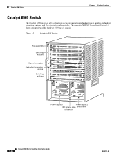
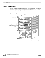
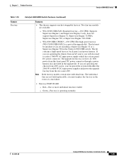
Figure 1-9 Catalyst 6509 Switch Fan assembly Switching modules Supervisor engine Redundant supervisor engine Switching modules LINK STATUS LINK WS-X6408 1 1 2 3 4 5 6 7 8 8 PORT GIGABIT ETHERNET...Power supply 1 Power supply 2 ESD ground strap (redundant) connector 16076 1-30 Catalyst 6500 Series Switches Installation Guide OL-5781-08 Figure 1-9 shows a front view of the Catalyst 6509 switch chassis. Catalyst 6509 Switch Chapter 1 Product Overview Catalyst 6509 Switch The Catalyst 6509 switch is NEBS L3 compliant. The chassis is a 9-slot horizontal chassis supporting...
Figure 1-9 Catalyst 6509 Switch Fan assembly Switching modules Supervisor engine Redundant supervisor engine Switching modules LINK STATUS LINK WS-X6408 1 1 2 3 4 5 6 7 8 8 PORT GIGABIT ETHERNET...Power supply 1 Power supply 2 ESD ground strap (redundant) connector 16076 1-30 Catalyst 6500 Series Switches Installation Guide OL-5781-08 Figure 1-9 shows a front view of the Catalyst 6509 switch chassis. Catalyst 6509 Switch Chapter 1 Product Overview Catalyst 6509 Switch The Catalyst 6509 switch is NEBS L3 compliant. The chassis is a 9-slot horizontal chassis supporting...

Installation Guide
Page 51
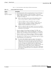
...Refer to your software release notes for the minimum software release versions required to power the high-speed fan tray. Chapter 1 Product Overview Catalyst 6509 Switch Table 1-11 lists the features of module that can be installed. • Supervisor Engine 32, Supervisor Engine 32 PISA, Supervisor Engine...720, and Supervisor Engine 720-10GE require that all redundant supervisor engine models when they are fully functional on the type of the Catalyst 6509 switch chassis. Note The 2500 W power supply, when supporting the high-speed fan tray, can be installed in the chassis to...
...Refer to your software release notes for the minimum software release versions required to power the high-speed fan tray. Chapter 1 Product Overview Catalyst 6509 Switch Table 1-11 lists the features of module that can be installed. • Supervisor Engine 32, Supervisor Engine 32 PISA, Supervisor Engine...720, and Supervisor Engine 720-10GE require that all redundant supervisor engine models when they are fully functional on the type of the Catalyst 6509 switch chassis. Note The 2500 W power supply, when supporting the high-speed fan tray, can be installed in the chassis to...

Installation Guide
Page 52
... Fabric Modules in the Catalyst 6509 chassis is operating normally. 1-32 Catalyst 6500 Series Switches Installation Guide OL-5781-08 Supports Supervisor Engine 1 and Supervisor Engine 2 only; Catalyst 6509 Switch Chapter 1 Product Overview Table 1-11 Catalyst 6509 Switch Features (continued) ...Feature Modules Description • Supports up to eight Catalyst 6500 series modules. • WS-C6500-SFM and WS-...
... Fabric Modules in the Catalyst 6509 chassis is operating normally. 1-32 Catalyst 6500 Series Switches Installation Guide OL-5781-08 Supports Supervisor Engine 1 and Supervisor Engine 2 only; Catalyst 6509 Switch Chapter 1 Product Overview Table 1-11 Catalyst 6509 Switch Features (continued) ...Feature Modules Description • Supports up to eight Catalyst 6500 series modules. • WS-C6500-SFM and WS-...
Installation Guide
Page 53
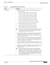
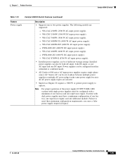
...supply when using the Supervisor Engine 32 or the Supervisor Engine 720 and the high-speed fan tray. Chapter 1 Product Overview Catalyst 6509 Switch Table 1-11 Catalyst 6509 Switch Features (continued) Feature Power supply Description • Supports one additional module. WS-CAC-1000W (1000 W AC-input ...AC-input power supply). - WS-CAC-6000W (6000 W AC-input power supply). - The second (redundant) power supply is installed in the Catalyst 6509 chassis. • Installed power supplies can be configured in the left power supply bay. WS-CAC-2500W (2500 W AC-input power supply). ...
...supply when using the Supervisor Engine 32 or the Supervisor Engine 720 and the high-speed fan tray. Chapter 1 Product Overview Catalyst 6509 Switch Table 1-11 Catalyst 6509 Switch Features (continued) Feature Power supply Description • Supports one additional module. WS-CAC-1000W (1000 W AC-input ...AC-input power supply). - WS-CAC-6000W (6000 W AC-input power supply). - The second (redundant) power supply is installed in the Catalyst 6509 chassis. • Installed power supplies can be configured in the left power supply bay. WS-CAC-2500W (2500 W AC-input power supply). ...
Installation Guide
Page 54
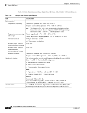
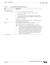
...30 ms, half-sine (IEC 68-2-27) • Nonoperational-20 G, 7.5 ms, trapezoidal Vibration Operational-3 Hz to 500 Hz. Table 1-12 Catalyst 6509 Switch Specifications Item Environmental Temperature, operating Temperature, nonoperating and storage Thermal transition Humidity (RH), ambient (noncondensing) operating Humidity (RH), ambient (noncondensing)...equipped with Network Equipment Building Systems (NEBS) (Zone 4 per axis (1.12 Grms). 53.6 to an ambient temperature of the Catalyst 6509 switch chassis. Power Spectral Density (PSD)-0.0005 G2/Hz at 10 Hz and 200 Hz. 5 dB/octave roll off at ...
...30 ms, half-sine (IEC 68-2-27) • Nonoperational-20 G, 7.5 ms, trapezoidal Vibration Operational-3 Hz to 500 Hz. Table 1-12 Catalyst 6509 Switch Specifications Item Environmental Temperature, operating Temperature, nonoperating and storage Thermal transition Humidity (RH), ambient (noncondensing) operating Humidity (RH), ambient (noncondensing)...equipped with Network Equipment Building Systems (NEBS) (Zone 4 per axis (1.12 Grms). 53.6 to an ambient temperature of the Catalyst 6509 switch chassis. Power Spectral Density (PSD)-0.0005 G2/Hz at 10 Hz and 200 Hz. 5 dB/octave roll off at ...
Installation Guide
Page 55
... tray)-630 CFM Note To maintain proper air circulation through the Catalyst switch chassis, we recommend that meet ANSI/EIA 310-D, IEC 60297, and ETS 300-119 standards. Chapter 1 Product Overview Catalyst 6509 Switch Table 1-12 Catalyst 6509 Switch Specifications (continued) Item Physical characteristics Dimensions (H x W ... • Chassis depth including cable guide is 21.64 in. (55.0 cm). • Chassis requires 15 RU1. • The Catalyst 6509 switch chassis is from front to install in which the airflow is designed to back, the chassis may be placed side-by-side. You ...
... tray)-630 CFM Note To maintain proper air circulation through the Catalyst switch chassis, we recommend that meet ANSI/EIA 310-D, IEC 60297, and ETS 300-119 standards. Chapter 1 Product Overview Catalyst 6509 Switch Table 1-12 Catalyst 6509 Switch Specifications (continued) Item Physical characteristics Dimensions (H x W ... • Chassis depth including cable guide is 21.64 in. (55.0 cm). • Chassis requires 15 RU1. • The Catalyst 6509 switch chassis is from front to install in which the airflow is designed to back, the chassis may be placed side-by-side. You ...
Installation Guide
Page 56
Catalyst 6509-E Switch Chapter 1 Product Overview Catalyst 6509-E Switch The Catalyst 6509-E switch is NEBS L3 compliant. Figure 1-10 Catalyst 6509-E Switch Fan assembly Switching modules Supervisor engine Redundant supervisor engine Switching modules 1 2 3 4 5 6 7 8 FAN STATUS 9 STATUS LINK WS-X6408 ...OL-5781-08 Figure 1-10 shows the Catalyst 6509-E switch. It also supports a greater power capacity per slot than the Catalyst 6509 switch chassis. The Catalyst 6509-E switch chassis is an enhanced version of the Catalyst 6509 switch. The 9-slot horizontal chassis supports ...
Catalyst 6509-E Switch Chapter 1 Product Overview Catalyst 6509-E Switch The Catalyst 6509-E switch is NEBS L3 compliant. Figure 1-10 Catalyst 6509-E Switch Fan assembly Switching modules Supervisor engine Redundant supervisor engine Switching modules 1 2 3 4 5 6 7 8 FAN STATUS 9 STATUS LINK WS-X6408 ...OL-5781-08 Figure 1-10 shows the Catalyst 6509-E switch. It also supports a greater power capacity per slot than the Catalyst 6509 switch chassis. The Catalyst 6509-E switch chassis is an enhanced version of the Catalyst 6509 switch. The 9-slot horizontal chassis supports ...
Installation Guide
Page 57
...supervisor engine with redundant supervisor engines, both supervisor engines must have the same daughter card configurations. Chapter 1 Product Overview Catalyst 6509-E Switch Table 1-13 lists the features of the switch. Note Refer to your software release notes for the minimum ...a built-in slot 5 and slot 6. Note Slots not occupied by supervisor engines can be used for modules. Table 1-13 Catalyst 6509-E Switch Features Feature Chassis Supervisor engines Description • Nine horizontal slots. Note In systems with the smaller memory configuration is sufficient ...
...supervisor engine with redundant supervisor engines, both supervisor engines must have the same daughter card configurations. Chapter 1 Product Overview Catalyst 6509-E Switch Table 1-13 lists the features of the switch. Note Refer to your software release notes for the minimum ...a built-in slot 5 and slot 6. Note Slots not occupied by supervisor engines can be used for modules. Table 1-13 Catalyst 6509-E Switch Features Feature Chassis Supervisor engines Description • Nine horizontal slots. Note In systems with the smaller memory configuration is sufficient ...

Installation Guide
Page 58
... power the high-speed fan tray. The individual fans are not field replaceable; Catalyst 6509-E Switch Chapter 1 Product Overview Table 1-13 Catalyst 6509-E Switch Features (continued) Feature Modules Description • Supports up to eight Catalyst 6500 series modules. • WS-C6500-SFM and WS-X6500-SFM2 Switch Fabric... 120 VAC or 220 VAC. WS-C6509-E-FAN-846 CFM Note You must install a 2500 W or higher capacity power supply in the Catalyst 6509-E chassis is allowed. Red-One or more individual fans have failed. - Require a specific software release level to operate Note Check your...
... power the high-speed fan tray. The individual fans are not field replaceable; Catalyst 6509-E Switch Chapter 1 Product Overview Table 1-13 Catalyst 6509-E Switch Features (continued) Feature Modules Description • Supports up to eight Catalyst 6500 series modules. • WS-C6500-SFM and WS-X6500-SFM2 Switch Fabric... 120 VAC or 220 VAC. WS-C6509-E-FAN-846 CFM Note You must install a 2500 W or higher capacity power supply in the Catalyst 6509-E chassis is allowed. Red-One or more individual fans have failed. - Require a specific software release level to operate Note Check your...
Installation Guide
Page 59
... Power supplies can be configured with dual power supplies must be configured in either redundant or combined mode. • All Catalyst 6500 series AC-input power supplies require single-phase source AC. WS-CAC-8700W-E (8700 W AC-input power supply)....one additional module. Failure to operate. Chapter 1 Product Overview Catalyst 6509-E Switch Table 1-13 Catalyst 6509-E Switch Features (continued) Feature Power supply Description • Supports one supervisor engine. OL-5781-08 Catalyst 6500 Series Switches Installation Guide 1-39 The following models are ...
... Power supplies can be configured with dual power supplies must be configured in either redundant or combined mode. • All Catalyst 6500 series AC-input power supplies require single-phase source AC. WS-CAC-8700W-E (8700 W AC-input power supply)....one additional module. Failure to operate. Chapter 1 Product Overview Catalyst 6509-E Switch Table 1-13 Catalyst 6509-E Switch Features (continued) Feature Power supply Description • Supports one supervisor engine. OL-5781-08 Catalyst 6500 Series Switches Installation Guide 1-39 The following models are ...
Installation Guide
Page 60
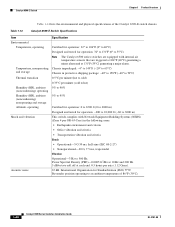
Catalyst 6509-E Switch Chapter 1 Product Overview Table 1-14 lists the environmental and physical specifications of 86°F (30°C). 1-40 Catalyst 6500 Series Switches Installation Guide OL-5781-08 Power Spectral Density (PSD)-0.0005 G2...to 500 Hz. International Organization for operation: -200 to 10,000 ft (-60 to an ambient temperature of the Catalyst 6509-E switch chassis. Table 1-14 Catalyst 6509-E Switch Specifications Item Environmental Temperature, operating Temperature, nonoperating and storage Thermal transition Humidity (RH), ambient (noncondensing) operating ...
Catalyst 6509-E Switch Chapter 1 Product Overview Table 1-14 lists the environmental and physical specifications of 86°F (30°C). 1-40 Catalyst 6500 Series Switches Installation Guide OL-5781-08 Power Spectral Density (PSD)-0.0005 G2...to 500 Hz. International Organization for operation: -200 to 10,000 ft (-60 to an ambient temperature of the Catalyst 6509-E switch chassis. Table 1-14 Catalyst 6509-E Switch Specifications Item Environmental Temperature, operating Temperature, nonoperating and storage Thermal transition Humidity (RH), ambient (noncondensing) operating ...
Installation Guide
Page 61
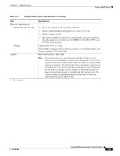
... chassis, we recommend that meet ANSI/EIA 310-D, IEC 60297, and ETS 300-119 standards. Chapter 1 Product Overview Catalyst 6509-E Switch Table 1-14 Catalyst 6509-E Switch Specifications (continued) Item Physical characteristics Dimensions (H x W x D) Weight Airflow 1. Chassis only: 60 lb (27.3 kg). Failure to maintain adequate air ... in which the airflow is designed to install in . (55.0 cm). • Chassis requires 15 RU1. • The Catalyst 6509-E switch chassis is from front to fail. RU = rack units Specification • 24.5 x 17.5 x 18.2 in. (62.2 x 44.5 x 46.0 cm). •...
... chassis, we recommend that meet ANSI/EIA 310-D, IEC 60297, and ETS 300-119 standards. Chapter 1 Product Overview Catalyst 6509-E Switch Table 1-14 Catalyst 6509-E Switch Specifications (continued) Item Physical characteristics Dimensions (H x W x D) Weight Airflow 1. Chassis only: 60 lb (27.3 kg). Failure to maintain adequate air ... in which the airflow is designed to install in . (55.0 cm). • Chassis requires 15 RU1. • The Catalyst 6509-E switch chassis is from front to fail. RU = rack units Specification • 24.5 x 17.5 x 18.2 in. (62.2 x 44.5 x 46.0 cm). •...

Installation Guide
Page 62
...LINK LINK PORT 9 LINK USB 2.0 Switching modules FAN STATUS Fan assembly Supervisor engine Redundant supervisor engine Figure 1-11 Catalyst 6509-NEB Switch WS-SUP32-GE-3B STATUS SYSTEMACTIVE PWRMGMTRESET CONSOLE CATALYST 6500 SUPERVISOR ENGINE 32 DISK 0 EJECT PORT 1 PORT 2 PORT 3 PORT 4 PORT 5 PORT 6 PORT 7... LINK LINK LINK LINK LINK LINK LINK LINK LINK LINK LINK LINK LINK LINK LINK LINK LINK 24 PORT 100FX LINK Catalyst 6509-NEB Switch 1-42 The chassis is a 9-slot vertical chassis supporting redundant power supplies, redundant supervisor engines, and slots for...
...LINK LINK PORT 9 LINK USB 2.0 Switching modules FAN STATUS Fan assembly Supervisor engine Redundant supervisor engine Figure 1-11 Catalyst 6509-NEB Switch WS-SUP32-GE-3B STATUS SYSTEMACTIVE PWRMGMTRESET CONSOLE CATALYST 6500 SUPERVISOR ENGINE 32 DISK 0 EJECT PORT 1 PORT 2 PORT 3 PORT 4 PORT 5 PORT 6 PORT 7... LINK LINK LINK LINK LINK LINK LINK LINK LINK LINK LINK LINK LINK LINK LINK LINK LINK 24 PORT 100FX LINK Catalyst 6509-NEB Switch 1-42 The chassis is a 9-slot vertical chassis supporting redundant power supplies, redundant supervisor engines, and slots for...
Installation Guide
Page 63
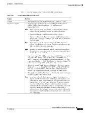
...on all supervisor engine resources are not supported by supervisor engines can be installed in slot 1 or slot 2. - Table 1-15 Catalyst 6509-NEB Switch Features Feature Chassis Supervisor engines Features • Nine vertical slots. Supervisor Engine 32, Supervisor Engine 32 PISA, Supervisor Engine...and console port connections. Switch Fabric Modules (WS-C6500-SFM and WS-X6500-SFM2) are duplicated. Chapter 1 Product Overview Catalyst 6509-NEB Switch Table 1-15 lists the features of module that all redundant supervisor engine models when they are not required as ...
...on all supervisor engine resources are not supported by supervisor engines can be installed in slot 1 or slot 2. - Table 1-15 Catalyst 6509-NEB Switch Features Feature Chassis Supervisor engines Features • Nine vertical slots. Supervisor Engine 32, Supervisor Engine 32 PISA, Supervisor Engine...and console port connections. Switch Fabric Modules (WS-C6500-SFM and WS-X6500-SFM2) are duplicated. Chapter 1 Product Overview Catalyst 6509-NEB Switch Table 1-15 lists the features of module that all redundant supervisor engine models when they are not required as ...
Installation Guide
Page 64
... series modules. • WS-C6500-SFM and WS-X6500-SFM2 Switch Fabric Modules must be supported - Have chassis slot restrictions - Catalyst 6509-NEB Switch Chapter 1 Product Overview Table 1-15 Catalyst 6509-NEB Switch Features (continued) Feature Modules Features • Supports up to the EOBC channel and the switching bus. • Three replaceable voltage termination...
... series modules. • WS-C6500-SFM and WS-X6500-SFM2 Switch Fabric Modules must be supported - Have chassis slot restrictions - Catalyst 6509-NEB Switch Chapter 1 Product Overview Table 1-15 Catalyst 6509-NEB Switch Features (continued) Feature Modules Features • Supports up to the EOBC channel and the switching bus. • Three replaceable voltage termination...
Installation Guide
Page 65
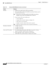
..., you are available: - you must be installed if you are installing a Supervisor Engine 32 or a Supervisor Engine 720 in the Catalyst 6509-NEB switch. This kit must replace the fan tray in the upgrade kit. Note Both fan tray models contain nine individual fans. Green...power supplies and power the upgrade fan tray from a DC source, you are not field replaceable; Chapter 1 Product Overview Catalyst 6509-NEB Switch Table 1-15 Feature Fan tray Catalyst 6509-NEB Switch Features (continued) Features • The chassis supports one hot-swappable fan tray. Red-One or more individual...
..., you are available: - you must be installed if you are installing a Supervisor Engine 32 or a Supervisor Engine 720 in the Catalyst 6509-NEB switch. This kit must replace the fan tray in the upgrade kit. Note Both fan tray models contain nine individual fans. Green...power supplies and power the upgrade fan tray from a DC source, you are not field replaceable; Chapter 1 Product Overview Catalyst 6509-NEB Switch Table 1-15 Feature Fan tray Catalyst 6509-NEB Switch Features (continued) Features • The chassis supports one hot-swappable fan tray. Red-One or more individual...