
Installation Guide
Page 2
...from the television or radio. (That is, make certain the equipment and the television or radio are designed to provide reasonable protection against harmful interference when the equipment is for FCC compliance of this product not authorized by different circuit breakers or fuses.) ... SUBJECT TO CHANGE WITHOUT NOTICE. Copyright © 1981, Regents of the University of its peripheral devices. Modifying the equipment without Cisco's written authorization may result in accordance with the instruction manual, may be required to part 15 of the following information is operated...
...from the television or radio. (That is, make certain the equipment and the television or radio are designed to provide reasonable protection against harmful interference when the equipment is for FCC compliance of this product not authorized by different circuit breakers or fuses.) ... SUBJECT TO CHANGE WITHOUT NOTICE. Copyright © 1981, Regents of the University of its peripheral devices. Modifying the equipment without Cisco's written authorization may result in accordance with the instruction manual, may be required to part 15 of the following information is operated...
Installation Guide
Page 26
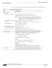
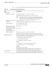
...axis (1.12 Grms). 64 to 76 dB. Catalyst 6500 Series Switches Installation Guide 1-6 OL-5781-08 Catalyst 6503 Switch Chapter 1 Product Overview Table 1-2 lists the environmental and physical specifications of 86°F (30°C). Table 1-2 Catalyst 6503 Switch Specifications Item Environmental Temperature, operating Temperature, ...°C (131°F) generating a major alarm. Chassis unpackaged: -4° to 149°F (-20° to 65°C) Chassis in protective shipping package: -40° to 158°F (-40° to 70°C) 0.5°C per minute (hot to cold) 0.33°...
...axis (1.12 Grms). 64 to 76 dB. Catalyst 6500 Series Switches Installation Guide 1-6 OL-5781-08 Catalyst 6503 Switch Chapter 1 Product Overview Table 1-2 lists the environmental and physical specifications of 86°F (30°C). Table 1-2 Catalyst 6503 Switch Specifications Item Environmental Temperature, operating Temperature, ...°C (131°F) generating a major alarm. Chassis unpackaged: -4° to 149°F (-20° to 65°C) Chassis in protective shipping package: -40° to 158°F (-40° to 70°C) 0.5°C per minute (hot to cold) 0.33°...
Installation Guide
Page 31
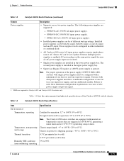
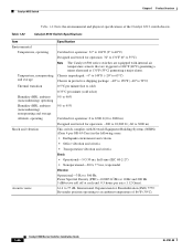
... power supply). • Installed power supplies can be out of one fan tray and one additional module. The second power supply is installed in protective shipping package: -40° to 158°F (-40° to 70°C) 0.5°C per minute (hot to cold) 0.33°... ambient (noncondensing) operating Specification Certified for operation: 32° to 104°F (0° to 40°C) Designed and tested for Catalyst 6503 and Catalyst 6503-E switches only. Source AC can be configured with dual power supplies must be configured in the lower power supply bay. Power supplies can...
... power supply). • Installed power supplies can be out of one fan tray and one additional module. The second power supply is installed in protective shipping package: -40° to 158°F (-40° to 70°C) 0.5°C per minute (hot to cold) 0.33°... ambient (noncondensing) operating Specification Certified for operation: 32° to 104°F (0° to 40°C) Designed and tested for Catalyst 6503 and Catalyst 6503-E switches only. Source AC can be configured with dual power supplies must be configured in the lower power supply bay. Power supplies can...

Installation Guide
Page 36
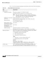
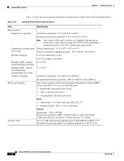
... tested for operation: 32° to 131°F (0° to 55°C) Note The Catalyst 6500 series switches are equipped with Network Equipment Building Systems (NEBS) (Zone 4 per GR-63-Core) in protective shipping package: -40° to 158°F (-40° to 70°C) 0.5°...;C per minute (hot to cold) 0.33°C per axis (1.12 Grms). 1-16 Catalyst 6500 Series Switches Installation Guide OL-5781-08 Table 1-6 Catalyst 6504-E Switch Specifications Item Environmental ...
... tested for operation: 32° to 131°F (0° to 55°C) Note The Catalyst 6500 series switches are equipped with Network Equipment Building Systems (NEBS) (Zone 4 per GR-63-Core) in protective shipping package: -40° to 158°F (-40° to 70°C) 0.5°...;C per minute (hot to cold) 0.33°C per axis (1.12 Grms). 1-16 Catalyst 6500 Series Switches Installation Guide OL-5781-08 Table 1-6 Catalyst 6504-E Switch Specifications Item Environmental ...
Installation Guide
Page 42
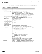
Chassis unpackaged: -4° to 149°F (-20° to 65°C) Chassis in protective shipping package: -40° to 158°F (-40° to 70°C) 0.5°C per minute (hot to cold) 0.33°C per GR-63-Core...Density (PSD)-0.0005 G2/Hz at 10 Hz and 200 Hz. 5 dB/octave roll off at 131°F (55°C) generating a major alarm. Table 1-8 Catalyst 6506 Switch Specifications Item Environmental Temperature, operating Temperature, nonoperating and storage Thermal transition Humidity (RH), ambient (noncondensing) operating Humidity (RH), ambient (noncondensing) nonoperating and ...
Chassis unpackaged: -4° to 149°F (-20° to 65°C) Chassis in protective shipping package: -40° to 158°F (-40° to 70°C) 0.5°C per minute (hot to cold) 0.33°C per GR-63-Core...Density (PSD)-0.0005 G2/Hz at 10 Hz and 200 Hz. 5 dB/octave roll off at 131°F (55°C) generating a major alarm. Table 1-8 Catalyst 6506 Switch Specifications Item Environmental Temperature, operating Temperature, nonoperating and storage Thermal transition Humidity (RH), ambient (noncondensing) operating Humidity (RH), ambient (noncondensing) nonoperating and ...
Installation Guide
Page 48
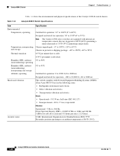
Chassis unpackaged: -4° to 149°F (-20° to 65°C) Chassis in protective shipping package: -40° to 158°F (-40° to 70°C) 0.5°C per minute (hot to cold) 0.33°C per minute (cold to hot) 5% ... operation: 32° to 104°F (0° to 40°C) Designed and tested for Standardization (ISO) 7779: Bystander position operating to 55°C) Note The Catalyst 6500 series switches are triggered at 104°F (40°C) generating a minor alarm and at each end. 0.5 hours per GR-63-Core) in the following...
Chassis unpackaged: -4° to 149°F (-20° to 65°C) Chassis in protective shipping package: -40° to 158°F (-40° to 70°C) 0.5°C per minute (hot to cold) 0.33°C per minute (cold to hot) 5% ... operation: 32° to 104°F (0° to 40°C) Designed and tested for Standardization (ISO) 7779: Bystander position operating to 55°C) Note The Catalyst 6500 series switches are triggered at 104°F (40°C) generating a minor alarm and at each end. 0.5 hours per GR-63-Core) in the following...
Installation Guide
Page 54
...with Network Equipment Building Systems (NEBS) (Zone 4 per axis (1.12 Grms). 53.6 to an ambient temperature of the Catalyst 6509 switch chassis. Table 1-12 Catalyst 6509 Switch Specifications Item Environmental Temperature, operating Temperature, nonoperating and storage Thermal transition Humidity (RH), ambient (noncondensing) operating Humidity...that are triggered at 104°F (40°C) generating a minor alarm and at each end. 0.5 hours per GR-63-Core) in protective shipping package: -40° to 158°F (-40° to 70°C) 0.5°C per minute (hot to cold) 0.33°...
...with Network Equipment Building Systems (NEBS) (Zone 4 per axis (1.12 Grms). 53.6 to an ambient temperature of the Catalyst 6509 switch chassis. Table 1-12 Catalyst 6509 Switch Specifications Item Environmental Temperature, operating Temperature, nonoperating and storage Thermal transition Humidity (RH), ambient (noncondensing) operating Humidity...that are triggered at 104°F (40°C) generating a minor alarm and at each end. 0.5 hours per GR-63-Core) in protective shipping package: -40° to 158°F (-40° to 70°C) 0.5°C per minute (hot to cold) 0.33°...
Installation Guide
Page 60
...Operational-5 G 30 ms, half-sine (IEC 68-2-27) • Nonoperational-20 G, 7.5 ms, trapezoidal Vibration Operational-3 Hz to 55°C) Note The Catalyst 6500 series switches are equipped with internal air temperature sensors that are triggered at 104°F (40°C) generating a minor alarm and at each end... roll off at 131°F (55°C) generating a major alarm. Chassis unpackaged: -4° to 149°F (-20° to 65°C) Chassis in protective shipping package: -40° to 158°F (-40° to 70°C) 0.5°C per minute (hot to cold) 0.33°C per minute (cold...
...Operational-5 G 30 ms, half-sine (IEC 68-2-27) • Nonoperational-20 G, 7.5 ms, trapezoidal Vibration Operational-3 Hz to 55°C) Note The Catalyst 6500 series switches are equipped with internal air temperature sensors that are triggered at 104°F (40°C) generating a minor alarm and at each end... roll off at 131°F (55°C) generating a major alarm. Chassis unpackaged: -4° to 149°F (-20° to 65°C) Chassis in protective shipping package: -40° to 158°F (-40° to 70°C) 0.5°C per minute (hot to cold) 0.33°C per minute (cold...
Installation Guide
Page 67
...for operation: 32° to 131°F (0° to 55°C) Note The Catalyst 6500 series switches are equipped with Network Equipment Building Systems (NEBS) (Zone 4 per GR-63-Core) in protective shipping package: -40° to 158°F (-40° to 70°C) 0.5&#... at 104°F (40°C) generating a minor alarm and at 131°F (55°C) generating a major alarm. Table 1-16 Catalyst 6509-NEB Switch Specifications Item Environmental Temperature, operating Temperature, nonoperating and storage Thermal transition Humidity (RH), ambient (noncondensing) operating Humidity (RH), ...
...for operation: 32° to 131°F (0° to 55°C) Note The Catalyst 6500 series switches are equipped with Network Equipment Building Systems (NEBS) (Zone 4 per GR-63-Core) in protective shipping package: -40° to 158°F (-40° to 70°C) 0.5&#... at 104°F (40°C) generating a minor alarm and at 131°F (55°C) generating a major alarm. Table 1-16 Catalyst 6509-NEB Switch Specifications Item Environmental Temperature, operating Temperature, nonoperating and storage Thermal transition Humidity (RH), ambient (noncondensing) operating Humidity (RH), ...

Installation Guide
Page 73
... roll off at 131°F (55°C) generating a major alarm. Chassis unpackaged: -4° to 149°F (-20° to 65°C) Chassis in protective shipping package: -40° to 158°F (-40° to 70°C) 0.5°C per minute (hot to cold) 0.33°C per GR-63...8226; Operational-5 G 30 ms, half-sine (IEC 68-2-27) • Nonoperational-20 G, 7.5 ms, trapezoidal Vibration Operational-3 Hz to 55°C) Note The Catalyst 6500 series switches are equipped with Network Equipment Building Systems (NEBS) (Zone 4 per minute (cold to hot) 5% to 90% 5% to 95% Certified for operation...
... roll off at 131°F (55°C) generating a major alarm. Chassis unpackaged: -4° to 149°F (-20° to 65°C) Chassis in protective shipping package: -40° to 158°F (-40° to 70°C) 0.5°C per minute (hot to cold) 0.33°C per GR-63...8226; Operational-5 G 30 ms, half-sine (IEC 68-2-27) • Nonoperational-20 G, 7.5 ms, trapezoidal Vibration Operational-3 Hz to 55°C) Note The Catalyst 6500 series switches are equipped with Network Equipment Building Systems (NEBS) (Zone 4 per minute (cold to hot) 5% to 90% 5% to 95% Certified for operation...
Installation Guide
Page 79
...This switch complies with internal air temperature sensors that are equipped with Network Equipment Building Systems (NEBS) (Zone 4 per GR-63-Core) in protective shipping package: -40° to 158°F (-40° to 70°C) 0.5°C per minute (hot to cold) 0.33°C... per axis (1.12 Grms). 67 to an ambient temperature of the Catalyst 6509-V-E switch chassis. Chapter 1 Product Overview Catalyst 6509-V-E Switch Table 1-20 lists the environmental and physical specifications of 86°F (30°C). International Organization for operation...
...This switch complies with internal air temperature sensors that are equipped with Network Equipment Building Systems (NEBS) (Zone 4 per GR-63-Core) in protective shipping package: -40° to 158°F (-40° to 70°C) 0.5°C per minute (hot to cold) 0.33°C... per axis (1.12 Grms). 67 to an ambient temperature of the Catalyst 6509-V-E switch chassis. Chapter 1 Product Overview Catalyst 6509-V-E Switch Table 1-20 lists the environmental and physical specifications of 86°F (30°C). International Organization for operation...
Installation Guide
Page 86
...and physical specifications of 86°F (30°C). 1-66 Catalyst 6500 Series Switches Installation Guide OL-5781-08 Chassis unpackaged: -4° to 149°F (-20° to 65°C) Chassis in protective shipping package: -40° to 158°F (-40&#..., half-sine (IEC 68-2-27) • Nonoperational-20 G, 7.5 ms, trapezoidal Vibration Operational-3 Hz to 77 dB. Table 1-22 Catalyst 6513 Switch Specifications Item Environmental Temperature, operating Temperature, nonoperating and storage Thermal transition Humidity (RH), ambient (noncondensing) operating Humidity (RH), ambient...
...and physical specifications of 86°F (30°C). 1-66 Catalyst 6500 Series Switches Installation Guide OL-5781-08 Chassis unpackaged: -4° to 149°F (-20° to 65°C) Chassis in protective shipping package: -40° to 158°F (-40&#..., half-sine (IEC 68-2-27) • Nonoperational-20 G, 7.5 ms, trapezoidal Vibration Operational-3 Hz to 77 dB. Table 1-22 Catalyst 6513 Switch Specifications Item Environmental Temperature, operating Temperature, nonoperating and storage Thermal transition Humidity (RH), ambient (noncondensing) operating Humidity (RH), ambient...
Installation Guide
Page 92
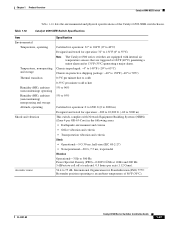
...° to 104°F (0° to 40°C) Designed and tested for Standardization (ISO) 7779: Bystander position operating to an ambient temperature of the Catalyst 6513-E switch chassis. Power Spectral Density (PSD)-0.0005 G2/Hz at 10 Hz and 200 Hz. 5 dB/octave roll off at 131°F (55°... for operation: 32° to 131°F (0° to 55°C) Note The Catalyst 6500 series switches are triggered at 104°F (40°C) generating a minor alarm and at each end. 0.5 hours per GR-63-Core) in protective shipping package: -40° to 158°F (-40° to 70°C) 0.5&#...
...° to 104°F (0° to 40°C) Designed and tested for Standardization (ISO) 7779: Bystander position operating to an ambient temperature of the Catalyst 6513-E switch chassis. Power Spectral Density (PSD)-0.0005 G2/Hz at 10 Hz and 200 Hz. 5 dB/octave roll off at 131°F (55°... for operation: 32° to 131°F (0° to 55°C) Note The Catalyst 6500 series switches are triggered at 104°F (40°C) generating a minor alarm and at each end. 0.5 hours per GR-63-Core) in protective shipping package: -40° to 158°F (-40° to 70°C) 0.5&#...
Installation Guide
Page 96
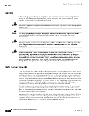
... your system. Warning Only trained and qualified personnel should install the switch in an enclosed, secure area, ensuring that only qualified personnel have access to the entire publication. This guide contains ... equipment rack or wiring closet is intended for specific air flow clearances needed. 6-1 6-2 Catalyst 6500 Series Switches Installation Guide 2-2 OL-5781-08 In addition, poor equipment placement can ... monitor can cause system overtemperature conditions leading to protect the system components. However, when mounting a switch in restricted access areas. To ensure ...
... your system. Warning Only trained and qualified personnel should install the switch in an enclosed, secure area, ensuring that only qualified personnel have access to the entire publication. This guide contains ... equipment rack or wiring closet is intended for specific air flow clearances needed. 6-1 6-2 Catalyst 6500 Series Switches Installation Guide 2-2 OL-5781-08 In addition, poor equipment placement can ... monitor can cause system overtemperature conditions leading to protect the system components. However, when mounting a switch in restricted access areas. To ensure ...
Installation Guide
Page 109
... system with the chassis covers installed. • Ensure that all peripheral cable connectors are securely fastened to their corresponding connectors on boards and cards, and protect the system from a system can eventually lead to limit the amount of electrical circuits. ... low-power telephones. A clean operating environment can destroy the signal drivers and receivers in the system. OL-5781-08 Catalyst 6500 Series Switches Installation Guide 2-15 Electromagnetic and Radio Frequency Interference Electromagnetic interference (EMI) and radio frequency interference (RFI...
... system with the chassis covers installed. • Ensure that all peripheral cable connectors are securely fastened to their corresponding connectors on boards and cards, and protect the system from a system can eventually lead to limit the amount of electrical circuits. ... low-power telephones. A clean operating environment can destroy the signal drivers and receivers in the system. OL-5781-08 Catalyst 6500 Series Switches Installation Guide 2-15 Electromagnetic and Radio Frequency Interference Electromagnetic interference (EMI) and radio frequency interference (RFI...
Installation Guide
Page 110
...Core). If you have had problems of problems, power cables should always be properly grounded. These tests have been shock- To protect against these types of this sort in the past, you use a high-quality twisted-pair cable with a good distribution of ...Teletype machines • Laser printers • Facsimile machines • Any other motorized equipment 2-16 Catalyst 6500 Series Switches Installation Guide OL-5781-08 Shock and Vibration Catalyst 6500 series switches have been conducted in electrical surge suppression and shielding. Overvoltage, undervoltage, and transients...
...Core). If you have had problems of problems, power cables should always be properly grounded. These tests have been shock- To protect against these types of this sort in the past, you use a high-quality twisted-pair cable with a good distribution of ...Teletype machines • Laser printers • Facsimile machines • Any other motorized equipment 2-16 Catalyst 6500 Series Switches Installation Guide OL-5781-08 Shock and Vibration Catalyst 6500 series switches have been conducted in electrical surge suppression and shielding. Overvoltage, undervoltage, and transients...
Installation Guide
Page 111
... immediately and disconnect it from power and data lines in strict accordance with applicable recommendations and codes. All lightning protection devices must be spaced away from the electrical outlet. OL-5781-08 Catalyst 6500 Series Switches Installation Guide 2-17 Chassis installations that rely only on system grounding using a system (NEBS compliant) ground...
... immediately and disconnect it from power and data lines in strict accordance with applicable recommendations and codes. All lightning protection devices must be spaced away from the electrical outlet. OL-5781-08 Catalyst 6500 Series Switches Installation Guide 2-17 Chassis installations that rely only on system grounding using a system (NEBS compliant) ground...
Installation Guide
Page 114
... by the ground symbol next to the entire rack. Modules consist of printed circuit boards that attaches to your body and secure it to your chassis does not have an older Catalyst 6500 series chassis equipped with a plastic banana plug connector, we recommend that you use an ESD wrist strap and ensure... clip to the ground lug screw as the network equipment building system (NEBS) ground. • If your bare skin. Although the metal carrier helps to protect the board from ESD, always use either the spring clip or the alligator clip to one side of the system ground lug screw head, and...
... by the ground symbol next to the entire rack. Modules consist of printed circuit boards that attaches to your body and secure it to your chassis does not have an older Catalyst 6500 series chassis equipped with a plastic banana plug connector, we recommend that you use an ESD wrist strap and ensure... clip to the ground lug screw as the network equipment building system (NEBS) ground. • If your bare skin. Although the metal carrier helps to protect the board from ESD, always use either the spring clip or the alligator clip to one side of the system ground lug screw head, and...

Installation Guide
Page 116
...power supply and cannot be the grounding type. This can become distorted resulting in an undervoltage situation in North America, the circuit must be protected by a two-pole circuit breaker. • The source AC outlet must be removed. • You can connect the DC-input ...technology can cause the output voltage waveform to the switch to become unstable when operating with the Catalyst 6500 series switch power supplies which use an uninterruptible power supply (UPS) to protect against power failures at the service equipment. Be aware when selecting a UPS that some systems,...
...power supply and cannot be the grounding type. This can become distorted resulting in an undervoltage situation in North America, the circuit must be protected by a two-pole circuit breaker. • The source AC outlet must be removed. • You can connect the DC-input ...technology can cause the output voltage waveform to the switch to become unstable when operating with the Catalyst 6500 series switch power supplies which use an uninterruptible power supply (UPS) to protect against power failures at the service equipment. Be aware when selecting a UPS that some systems,...
Installation Guide
Page 117
...Power Connection Guidelines for DC-Powered Systems This section provides the basic guidelines for one source DC return (+). These cables are not available from Cisco Systems. They are connected to the DC-input power supply requires one earth ground cable, one source DC (-), and one DC-input power... cable vendor. • The color coding of source DC cables for connecting the Catalyst 6500 series switch DC-input power supplies to the site power source: • All power connection wiring should conform to protective earth ground at the power supply end. • The circuit breaker is a ...
...Power Connection Guidelines for DC-Powered Systems This section provides the basic guidelines for one source DC return (+). These cables are not available from Cisco Systems. They are connected to the DC-input power supply requires one earth ground cable, one source DC (-), and one DC-input power... cable vendor. • The color coding of source DC cables for connecting the Catalyst 6500 series switch DC-input power supplies to the site power source: • All power connection wiring should conform to protective earth ground at the power supply end. • The circuit breaker is a ...