
Hardware Guide
Page 11
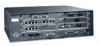
...The NPE-G1 and NPE-G2 also have a cable-management bracket. A fully configured Cisco 7200 series router operates with either an AC-input power receptacle, or three hardwired DC-input power leads (depending on the type of installed power supply). Chassis Overview-Rear View Figure 1-2 Cisco 7200 Series Router-Rear ... or a two-hole grounding lug (see Figure 1-2). Chapter 1 Cisco 7200 Series Port Adapter Installation Requirements Chassis Overview-Rear View Note A blank port adapter is installed in port adapter slot 5 in other Cisco 7000 family routers. Adjacent to the chassis.
...The NPE-G1 and NPE-G2 also have a cable-management bracket. A fully configured Cisco 7200 series router operates with either an AC-input power receptacle, or three hardwired DC-input power leads (depending on the type of installed power supply). Chassis Overview-Rear View Figure 1-2 Cisco 7200 Series Router-Rear ... or a two-hole grounding lug (see Figure 1-2). Chapter 1 Cisco 7200 Series Port Adapter Installation Requirements Chassis Overview-Rear View Note A blank port adapter is installed in port adapter slot 5 in other Cisco 7000 family routers. Adjacent to the chassis.

Hardware Guide
Page 12
... a mix of a Cisco 7200 series router configured with a single 280W AC-input power supply. (A power supply filler plate is installed over the second power supply bay.) Three internal fans draw cooling air into the chassis interior and across internal components to maintain an acceptable operating temperature (see Figure 1-2). When installed with the NPE-G1 or NPE-G2, the...
... a mix of a Cisco 7200 series router configured with a single 280W AC-input power supply. (A power supply filler plate is installed over the second power supply bay.) Three internal fans draw cooling air into the chassis interior and across internal components to maintain an acceptable operating temperature (see Figure 1-2). When installed with the NPE-G1 or NPE-G2, the...

Configuration Guide
Page 3
... x Obtaining Documentation and Submitting a Service Request xi Cisco 7200 VXR Product Overview 1-1 Physical Description 1-1 Software Requirements 1-4 Cisco 7204VXR Overview 1-4 Cisco 7206VXR Overview 1-7 Field-Replaceable Units 1-10 Network Processing Engine or Network Services Engine 1-11 Determining Memory Configuration 1-31 Input/Output Controller 1-32 LED Descriptions 1-40 NPE-G2 LEDs 1-41 NPE-G1 LEDs 1-42 Input/Output Controller C7200-I/O LEDs...
... x Obtaining Documentation and Submitting a Service Request xi Cisco 7200 VXR Product Overview 1-1 Physical Description 1-1 Software Requirements 1-4 Cisco 7204VXR Overview 1-4 Cisco 7206VXR Overview 1-7 Field-Replaceable Units 1-10 Network Processing Engine or Network Services Engine 1-11 Determining Memory Configuration 1-31 Input/Output Controller 1-32 LED Descriptions 1-40 NPE-G2 LEDs 1-41 NPE-G1 LEDs 1-42 Input/Output Controller C7200-I/O LEDs...

Configuration Guide
Page 4
... Contents 2-12 Site Log 2-13 3 C H A P T E R Installing a Cisco 7200 VXR Router 3-1 Rack-Mounting a Cisco 7200 VXR Router 3-2 Attaching the Chassis Rack-Mount and Cable-Management Brackets 3-7 Installing the Brackets on the Front of the Chassis 3-8 Installing the NPE-G1 and NPE-G2 Cable-Management Brackets on a Front-Mounted Router 3-9 Installing the NPE-G1 and NPE-G2 Optical Cable-Management Bracket 3-11 Installing...
... Contents 2-12 Site Log 2-13 3 C H A P T E R Installing a Cisco 7200 VXR Router 3-1 Rack-Mounting a Cisco 7200 VXR Router 3-2 Attaching the Chassis Rack-Mount and Cable-Management Brackets 3-7 Installing the Brackets on the Front of the Chassis 3-8 Installing the NPE-G1 and NPE-G2 Cable-Management Brackets on a Front-Mounted Router 3-9 Installing the NPE-G1 and NPE-G2 Optical Cable-Management Bracket 3-11 Installing...

Configuration Guide
Page 20
... requirements. Physical Description Chapter 1 Cisco 7200 VXR Product Overview The Cisco 7200 VXR routers support the high-speed network processing engine, NPE-G2, and all Cisco 7200 VXR routers and are described in the "Field-Replaceable Units" section on page 1-10. if one power supply is powered off and removed from the router, the second power supply immediately takes over the router's power requirements...
... requirements. Physical Description Chapter 1 Cisco 7200 VXR Product Overview The Cisco 7200 VXR routers support the high-speed network processing engine, NPE-G2, and all Cisco 7200 VXR routers and are described in the "Field-Replaceable Units" section on page 1-10. if one power supply is powered off and removed from the router, the second power supply immediately takes over the router's power requirements...

Configuration Guide
Page 21
... 149•F (-20 to 65•C) nonoperating Humidity 10 to the Port Adapter Jacket Card and provides unlimited bandwidth for the Cisco 7200 VXR physical specifications and power requirements: Table 1-1 Physical Specifications Description Specification Midplane Two primary PCI buses, and one port adapter. The NPE-G2 or NPE-G1 does not use bandwidth points. x 16.8 in .
... 149•F (-20 to 65•C) nonoperating Humidity 10 to the Port Adapter Jacket Card and provides unlimited bandwidth for the Cisco 7200 VXR physical specifications and power requirements: Table 1-1 Physical Specifications Description Specification Midplane Two primary PCI buses, and one port adapter. The NPE-G2 or NPE-G1 does not use bandwidth points. x 16.8 in .

Configuration Guide
Page 77
... 1-37 lists the DC power thresholds for the normal, warning, and critical (power supply-monitored) levels for most Cisco IOS releases, and Table 1-38 lists the DC power thresholds for the normal and critical (power supply-monitored) levels for...required. • Shutdown-The processor has detected a temperature condition that you can retrieve it later to avoid equipment damage from excessive heat. Table 1-34 lists the typical temperature thresholds for the NPE-G1. Table 1-35 lists the typical temperature thresholds for the NPE-G2. In addition, the power supplies monitor internal power...
... 1-37 lists the DC power thresholds for the normal, warning, and critical (power supply-monitored) levels for most Cisco IOS releases, and Table 1-38 lists the DC power thresholds for the normal and critical (power supply-monitored) levels for...required. • Shutdown-The processor has detected a temperature condition that you can retrieve it later to avoid equipment damage from excessive heat. Table 1-34 lists the typical temperature thresholds for the NPE-G1. Table 1-35 lists the typical temperature thresholds for the NPE-G2. In addition, the power supplies monitor internal power...
Configuration Guide
Page 84
... framing and ones density to connect a serial port to a T1 network. (Some telephone systems require a minimum number of 1 bits per time unit in a data stream, called ones density.) ... fixed in complete or intermittent system failures. never touch the boards or connector pins. Cisco 7200 VXR Installation and Configuration Guide 2-2 OL-5013-09 Electrical Equipment Guidelines Chapter 2 Preparing... or the rack-mount brackets • Two cable-management brackets for the NPE-G1 or NPE-G2 In addition, you must power down the system before removing or replacing the I /O controller, and port...
... framing and ones density to connect a serial port to a T1 network. (Some telephone systems require a minimum number of 1 bits per time unit in a data stream, called ones density.) ... fixed in complete or intermittent system failures. never touch the boards or connector pins. Cisco 7200 VXR Installation and Configuration Guide 2-2 OL-5013-09 Electrical Equipment Guidelines Chapter 2 Preparing... or the rack-mount brackets • Two cable-management brackets for the NPE-G1 or NPE-G2 In addition, you must power down the system before removing or replacing the I /O controller, and port...
Configuration Guide
Page 118
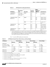
...0.20 fiber and 62.5/125 μm, NA = 0.275 fiber. 7. A mode-conditioning patch cord is required for link distances greater than 984 ft (300 m). Table 3-3 provides SFP module power information. For fiber types 50/125 μm MMF and 62.5/125 μm MMF. Table 3-3 SFP ... -9.5 dBm6 -4 dBm6 -17 dBm 0 dBm SFP-GE-Z= 0 dBm 5 dBm -23 dBm 0 dBm 1. Connecting I/O Controller, NPE-G1, or NPE-G2 Cables Chapter 3 Installing a Cisco 7200 VXR Router Table 3-2 SFP Module Port Cabling Specifications SFP Module 100BASE-FX SFP-GE-F= Wavelength (nm) Fiber Type 1270 (min) MMF 1300 (typical...
...0.20 fiber and 62.5/125 μm, NA = 0.275 fiber. 7. A mode-conditioning patch cord is required for link distances greater than 984 ft (300 m). Table 3-3 provides SFP module power information. For fiber types 50/125 μm MMF and 62.5/125 μm MMF. Table 3-3 SFP ... -9.5 dBm6 -4 dBm6 -17 dBm 0 dBm SFP-GE-Z= 0 dBm 5 dBm -23 dBm 0 dBm 1. Connecting I/O Controller, NPE-G1, or NPE-G2 Cables Chapter 3 Installing a Cisco 7200 VXR Router Table 3-2 SFP Module Port Cabling Specifications SFP Module 100BASE-FX SFP-GE-F= Wavelength (nm) Fiber Type 1270 (min) MMF 1300 (typical...

Configuration Guide
Page 120
... duplex connectors, one cable for transmit (TX) and a second cable for receive (RX). Connecting I/O Controller, NPE-G1, or NPE-G2 Cables Chapter 3 Installing a Cisco 7200 VXR Router Figure 3-17 Mode-Conditioning Patch Cord Assembly for an SFP Module 4 1 2 / / / / / /.... You can use of a plug-to-plug patch cord maximizes the power budget of duplex optical fibers, including a single-mode-to-multimode offset launch...from the center, which is required. See the "Fiber-Optic Cleaning Information" section on your I /O-GE+E or the NPE-G1. 3-24 Cisco 7200 VXR Installation and Configuration ...
... duplex connectors, one cable for transmit (TX) and a second cable for receive (RX). Connecting I/O Controller, NPE-G1, or NPE-G2 Cables Chapter 3 Installing a Cisco 7200 VXR Router Figure 3-17 Mode-Conditioning Patch Cord Assembly for an SFP Module 4 1 2 / / / / / /.... You can use of a plug-to-plug patch cord maximizes the power budget of duplex optical fibers, including a single-mode-to-multimode offset launch...from the center, which is required. See the "Fiber-Optic Cleaning Information" section on your I /O-GE+E or the NPE-G1. 3-24 Cisco 7200 VXR Installation and Configuration ...
Configuration Guide
Page 123
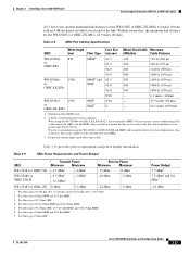
...). 3. For fiber type 10 μm SMF. For fiber types 9/125 μm SMF. 4. Table 3-9 GBIC Power Requirements and Power Budget GBIC Transmit Power Minimum Maximum Receive Power Minimum Maximum WS-G5484 or GBIC-SX WS-G5486 or GBIC-LXLH -9.5 dBm1 -9.5 dBm3 -11.5dBm4 -4 dBm1 -3... 3 Installing a Cisco 7200 VXR Router Connecting I/O Controller, NPE-G1, or NPE-G2 Cables is 6.5 feet (2 m), and the minimum link distance for very short link distance (tens of meters). Without attenuators, the minimum link distance for the WS-G5487= or GBIC-ZX-SM is required. A mode-conditioning...
...). 3. For fiber type 10 μm SMF. For fiber types 9/125 μm SMF. 4. Table 3-9 GBIC Power Requirements and Power Budget GBIC Transmit Power Minimum Maximum Receive Power Minimum Maximum WS-G5484 or GBIC-SX WS-G5486 or GBIC-LXLH -9.5 dBm1 -9.5 dBm3 -11.5dBm4 -4 dBm1 -3... 3 Installing a Cisco 7200 VXR Router Connecting I/O Controller, NPE-G1, or NPE-G2 Cables is 6.5 feet (2 m), and the minimum link distance for very short link distance (tens of meters). Without attenuators, the minimum link distance for the WS-G5487= or GBIC-ZX-SM is required. A mode-conditioning...

Configuration Guide
Page 167
.../O controller is installed: • The POWER ON LED on the NPE-G1 or the PWK OK LED on the NPE-G2 comes on immediately-and stays on-and indicates that the NPE-G1 is receiving DC power from the router midplane. This LED remains off when you start the router, it is damaged or not connected to...-09 Cisco 7200 VXR Installation and Configuration Guide 5-5 Proceed to the MII port on the I /O Controller" section on page 5-7. • The RJ-45 LINK LED comes on page 5-7. See the "Connecting to the I/O Controller Ethernet and Fast Ethernet Ports" section on page 3-30 in use are required for ...
.../O controller is installed: • The POWER ON LED on the NPE-G1 or the PWK OK LED on the NPE-G2 comes on immediately-and stays on-and indicates that the NPE-G1 is receiving DC power from the router midplane. This LED remains off when you start the router, it is damaged or not connected to...-09 Cisco 7200 VXR Installation and Configuration Guide 5-5 Proceed to the MII port on the I /O Controller" section on page 5-7. • The RJ-45 LINK LED comes on page 5-7. See the "Connecting to the I/O Controller Ethernet and Fast Ethernet Ports" section on page 3-30 in use are required for ...


