
Installation Guide
Page 48
... requires a different method. Caution The network processing engine and the I /O controller while the router is seamless to remove port adapters and service adapters and insert them . 1-30 Cisco 7206 Installation and Configuration Guide OL-5102-02 Functional Overview Chapter 1 Product Overview MAC Address All... address scheme allows you to install and replace port adapters and service adapters while the router is stored in the Cisco 7206 support online insertion and removal (OIR).This function allows you to end users on the network, maintains all routing information, and preserves ...
... requires a different method. Caution The network processing engine and the I /O controller while the router is seamless to remove port adapters and service adapters and insert them . 1-30 Cisco 7206 Installation and Configuration Guide OL-5102-02 Functional Overview Chapter 1 Product Overview MAC Address All... address scheme allows you to install and replace port adapters and service adapters while the router is stored in the Cisco 7206 support online insertion and removal (OIR).This function allows you to end users on the network, maintains all routing information, and preserves ...

Installation Guide
Page 64
...cables and devices connected ASCII terminal attached to provide a historical record of what was done by Date Date router received Router and all port and service adapters operational (enabled LEDs on the adapters and the I /O controller, network processing engine, and all... When the checklist is completed. Table 2-2 Cisco 7206 Installation Checklist Task Verified by whom, use the Cisco 7206 Installation Checklist in your site log (described at the end of this chapter) along with your new router. Cisco 7206 Installation Checklist Chapter 2 Preparing for Installation ...
...cables and devices connected ASCII terminal attached to provide a historical record of what was done by Date Date router received Router and all port and service adapters operational (enabled LEDs on the adapters and the I /O controller, network processing engine, and all... When the checklist is completed. Table 2-2 Cisco 7206 Installation Checklist Task Verified by whom, use the Cisco 7206 Installation Checklist in your site log (described at the end of this chapter) along with your new router. Cisco 7206 Installation Checklist Chapter 2 Preparing for Installation ...
Installation Guide
Page 79
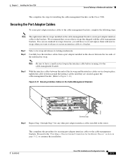
... with new tie wraps when you use standard tie wraps; Step 3 With the interface cables between the two ends of the tie wrap and the interface cables service loop in place, tighten the cable tie down around the interface cables until they are secured against the cable-... wrap and release its locking mechanism. Note Be sure to the "Providing a Chassis Ground Connection for the Router Chassis" section on the Cisco 7206. Proceed to leave a small service loop in the router. Securing the Port Adapter Cables To secure port adapter interface cables to the cable-management brackets, complete the ...
... with new tie wraps when you use standard tie wraps; Step 3 With the interface cables between the two ends of the tie wrap and the interface cables service loop in place, tighten the cable tie down around the interface cables until they are secured against the cable-... wrap and release its locking mechanism. Note Be sure to the "Providing a Chassis Ground Connection for the Router Chassis" section on the Cisco 7206. Proceed to leave a small service loop in the router. Securing the Port Adapter Cables To secure port adapter interface cables to the cable-management brackets, complete the ...
Installation Guide
Page 88
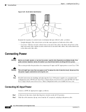
... RJ-45 cable, as follows: Step 1 At the rear of the router, check that the power switch is in the same sequence at both ends of the cable. • Crossover-The first (far left) colored wire at one end of the cable is the third colored wire at the other...supply cords before working with the system. Connecting Power Figure 3-20 RJ-45 Cable Identification Chapter 3 Installing the Cisco 7206 H5663 Examine the sequence of colored wires to your Cisco 7206. This guide contains important safety information you install, operate, or service the system, read the Site Preparation and Safety Guide.
... RJ-45 cable, as follows: Step 1 At the rear of the router, check that the power switch is in the same sequence at both ends of the cable. • Crossover-The first (far left) colored wire at one end of the cable is the third colored wire at the other...supply cords before working with the system. Connecting Power Figure 3-20 RJ-45 Cable Identification Chapter 3 Installing the Cisco 7206 H5663 Examine the sequence of colored wires to your Cisco 7206. This guide contains important safety information you install, operate, or service the system, read the Site Preparation and Safety Guide.
Installation Guide
Page 90
...3 Step 4 At the rear of the router, check that the power switch on the power supply is OFF, locate the circuit breaker on the panel board that services the DC circuit, switch the circuit breaker to...screw using a 3/16-inch flat-blade screwdriver (refer to Figure 3-22). Insert the stripped end of the circuit breaker in the OFF position. To ensure that all the way into the ground...no current is removed from the -V, +V, and ground leads (refer to Figure 3-23). 3-22 Cisco 7206 Installation and Configuration Guide OL-5102-02 Warning When you install the unit, the ground connection must...
...3 Step 4 At the rear of the router, check that the power switch on the power supply is OFF, locate the circuit breaker on the panel board that services the DC circuit, switch the circuit breaker to...screw using a 3/16-inch flat-blade screwdriver (refer to Figure 3-22). Insert the stripped end of the circuit breaker in the OFF position. To ensure that all the way into the ground...no current is removed from the -V, +V, and ground leads (refer to Figure 3-23). 3-22 Cisco 7206 Installation and Configuration Guide OL-5102-02 Warning When you install the unit, the ground connection must...

Installation Guide
Page 91
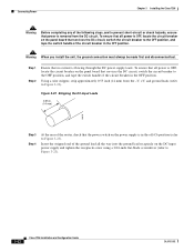
... all three leads (refer to cut the stripped end of the lead, and repeat Step 2 through Step 5. Chapter 3 Installing the Cisco 7206 Figure 3-23 Connecting DC-Input Power Power switch Connecting Power H8622 Cable tie Ground lead service loop DC power leads Step 5 Insert the stripped end of the +V lead all current-carrying conductors.
... all three leads (refer to cut the stripped end of the lead, and repeat Step 2 through Step 5. Chapter 3 Installing the Cisco 7206 Figure 3-23 Connecting DC-Input Power Power switch Connecting Power H8622 Cable tie Ground lead service loop DC power leads Step 5 Insert the stripped end of the +V lead all current-carrying conductors.

Installation Guide
Page 129
...the router, it does not indicate the state of the individual interfaces on the port adapters (service adapters do not indicate startup problems. • The enabled LED on each port and service adapter ... the Power Subsystem - Troubleshooting the Power Subsystem Check the following to Chapter 3, "Installing the Cisco 7206," the "Fast Ethernet Connection Equipment" section on the console screen. If the power OK... with the power subsystem: • On the first power supply, is connected at both ends. - If it is not displayed, refer to the "Console and Auxiliary Port Connection Equipment...
...the router, it does not indicate the state of the individual interfaces on the port adapters (service adapters do not indicate startup problems. • The enabled LED on each port and service adapter ... the Power Subsystem - Troubleshooting the Power Subsystem Check the following to Chapter 3, "Installing the Cisco 7206," the "Fast Ethernet Connection Equipment" section on the console screen. If the power OK... with the power subsystem: • On the first power supply, is connected at both ends. - If it is not displayed, refer to the "Console and Auxiliary Port Connection Equipment...
Configuration Guide
Page 9
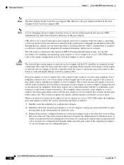
... the part is end-of this document. See the "Obtaining Documentation and Submitting a Service Request" section on page xi for more current than printed documentation. OL-5013-09 Cisco 7200 VXR Installation and Configuration Guide iii Cisco documentation and additional literature... page vi • Terms and Acronyms, page ix • Related Documentation, page x • Obtaining Documentation and Submitting a Service Request, page xi Document Revision History The Document Revision History below records technical changes to warnings. The Product Documentation DVD is organized, ...
... the part is end-of this document. See the "Obtaining Documentation and Submitting a Service Request" section on page xi for more current than printed documentation. OL-5013-09 Cisco 7200 VXR Installation and Configuration Guide iii Cisco documentation and additional literature... page vi • Terms and Acronyms, page ix • Related Documentation, page x • Obtaining Documentation and Submitting a Service Request, page xi Document Revision History The Document Revision History below records technical changes to warnings. The Product Documentation DVD is organized, ...

Configuration Guide
Page 21
... Hz6 AC-input cable 18 AWG7 three-wire cable, with a three-lead IEC-320 receptacle on the power supply end, and a country-dependent plug on the power source end DC-output power 280W maximum (with either a single or dual power supply configuration) DC-input voltage rating -48 ....34 cm x 42.67 cm x 43.18 cm) Weight Heat dissipation Chassis fully configured with a network processing engine or network services engine, I/O controller, maximum number of the PCI buses is 900 Mbps. x 16.8 in . x 17 in the European Community OL-5013-09 Cisco 7200 VXR Installation and Configuration Guide 1-3
... Hz6 AC-input cable 18 AWG7 three-wire cable, with a three-lead IEC-320 receptacle on the power supply end, and a country-dependent plug on the power source end DC-output power 280W maximum (with either a single or dual power supply configuration) DC-input voltage rating -48 ....34 cm x 42.67 cm x 43.18 cm) Weight Heat dissipation Chassis fully configured with a network processing engine or network services engine, I/O controller, maximum number of the PCI buses is 900 Mbps. x 16.8 in . x 17 in the European Community OL-5013-09 Cisco 7200 VXR Installation and Configuration Guide 1-3
Configuration Guide
Page 76
... router is seamless to end users on the port adapter back to the system as they were present (but not configured) at boot time. OIR allows you remove or insert a port adapter or service adapter in a Cisco 7200 VXR router, refer to the online configuration note for installing and replacing a port adapter or service adapter in a Cisco...
... router is seamless to end users on the port adapter back to the system as they were present (but not configured) at boot time. OIR allows you remove or insert a port adapter or service adapter in a Cisco 7200 VXR router, refer to the online configuration note for installing and replacing a port adapter or service adapter in a Cisco...
Configuration Guide
Page 110
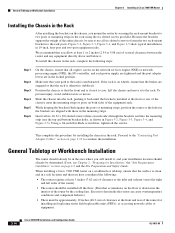
Make sure that the front end is closest to you. Position the chassis so that your installation location should already be determined. While keeping the brackets flush against the posts or mounting strips, position the router so the holes in the brackets are aligned with those in ... and replacing router field-replaceable units (FRUs), or accessing network cables or equipment. 3-14 Cisco 7200 VXR Installation and Configuration Guide OL-5013-09 To install the chassis in the locked position. Lift the chassis and move it . Insert all captive screws on the network services engine (NSE...
Make sure that the front end is closest to you. Position the chassis so that your installation location should already be determined. While keeping the brackets flush against the posts or mounting strips, position the router so the holes in the brackets are aligned with those in ... and replacing router field-replaceable units (FRUs), or accessing network cables or equipment. 3-14 Cisco 7200 VXR Installation and Configuration Guide OL-5013-09 To install the chassis in the locked position. Lift the chassis and move it . Insert all captive screws on the network services engine (NSE...
Configuration Guide
Page 112
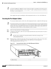
... between the ends of the tie wrap and the interface cables service loop in the chassis between the two ends of the Chassis" section on page 3-11. We recommend that you use standard tie wraps; Installing the Cable-Management Brackets Chapter 3 Installing a Cisco 7200 VXR Router Note If ... secure port adapter interface cables to the cable-management bracket. Note Be sure to leave a small service loop in the interface cable before securing it to the cable-management brackets, complete the following steps: Note The eight removable tie wraps installed on a Cisco 7200 VXR router.
... between the ends of the tie wrap and the interface cables service loop in the chassis between the two ends of the Chassis" section on page 3-11. We recommend that you use standard tie wraps; Installing the Cable-Management Brackets Chapter 3 Installing a Cisco 7200 VXR Router Note If ... secure port adapter interface cables to the cable-management bracket. Note Be sure to leave a small service loop in the interface cable before securing it to the cable-management brackets, complete the following steps: Note The eight removable tie wraps installed on a Cisco 7200 VXR router.
Configuration Guide
Page 114
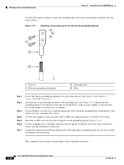
... router chassis. (See Figure 1-4 in Chapter 1, "Cisco 7206VXR Overview.") Insert the two screws through the holes in the grounding lug. (See Figure 3-14.) Ensure that the grounding lug does not interfere with other router hardware, such as power supplies or the network processing engine or network services .... this step is held firmly to the chassis. Connect the opposite end of the 6-AWG wire approximately 0.75 inches (19.05 mm). Attaching a Chassis Ground Connection Chapter 3 Installing a Cisco 7200 VXR Router Use the following procedure to attach the grounding lug to the chassis ...
... router chassis. (See Figure 1-4 in Chapter 1, "Cisco 7206VXR Overview.") Insert the two screws through the holes in the grounding lug. (See Figure 3-14.) Ensure that the grounding lug does not interfere with other router hardware, such as power supplies or the network processing engine or network services .... this step is held firmly to the chassis. Connect the opposite end of the 6-AWG wire approximately 0.75 inches (19.05 mm). Attaching a Chassis Ground Connection Chapter 3 Installing a Cisco 7200 VXR Router Use the following procedure to attach the grounding lug to the chassis ...
Configuration Guide
Page 139
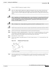
... the unit, always make the ground connection first and disconnect it last. To ensure that services the DC circuit, switch the circuit breaker to the off position, and tape the switch handle... of the circuit breaker in . (14 mm) Step 5 Insert the stripped end of the ground lead all power is removed from the -V, +V, and ground leads. (See Figure 3-32...running through the -V and +V leads. Disconnect the -V and +V leads. Chapter 3 Installing a Cisco 7200 VXR Router Connecting Power Connect a 280W DC-input power supply as follows: Note The color coding of the ...
... the unit, always make the ground connection first and disconnect it last. To ensure that services the DC circuit, switch the circuit breaker to the off position, and tape the switch handle... of the circuit breaker in . (14 mm) Step 5 Insert the stripped end of the ground lead all power is removed from the -V, +V, and ground leads. (See Figure 3-32...running through the -V and +V leads. Disconnect the -V and +V leads. Chapter 3 Installing a Cisco 7200 VXR Router Connecting Power Connect a 280W DC-input power supply as follows: Note The color coding of the ...
Configuration Guide
Page 140
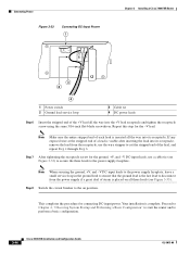
... and Configuration Guide OL-5013-09 Repeat this step for connecting DC-input power. Connecting Power Figure 3-33 Connecting DC-Input Power 1 Chapter 3 Installing a Cisco 7200 VXR Router 84542 3 2 4 1 Power switch 2 Ground lead service loop 3 Cable tie 4 DC power leads Step 6 Insert the stripped end of the +V lead all the way into its receptacle.
... and Configuration Guide OL-5013-09 Repeat this step for connecting DC-input power. Connecting Power Figure 3-33 Connecting DC-Input Power 1 Chapter 3 Installing a Cisco 7200 VXR Router 84542 3 2 4 1 Power switch 2 Ground lead service loop 3 Cable tie 4 DC power leads Step 6 Insert the stripped end of the +V lead all the way into its receptacle.
Configuration Guide
Page 144
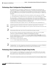
... Note Completing Step 3 saves the configuration settings that the AutoInstall process created to your Cisco 7200 VXR router for information about how AutoInstall works. This functionality is coordinated by your system administrator at...Cisco 7200 VXR router automatically after connection to NVRAM. Step 3 The router loads the operating system image from the router and the TCP/IP host are maintained: 1. Once the AutoInstall process is completed, use AutoInstall, do this task. If the remote end of the router synchronous serial connection to the channel service unit/data service...
... Note Completing Step 3 saves the configuration settings that the AutoInstall process created to your Cisco 7200 VXR router for information about how AutoInstall works. This functionality is coordinated by your system administrator at...Cisco 7200 VXR router automatically after connection to NVRAM. Step 3 The router loads the operating system image from the router and the TCP/IP host are maintained: 1. Once the AutoInstall process is completed, use AutoInstall, do this task. If the remote end of the router synchronous serial connection to the channel service unit/data service...
Configuration Guide
Page 168
Also see Chapter 3, "Installing a Cisco 7200 VXR Router," the "Connecting to the Console and Auxiliary Ports" section on page 3-34 ...is good, and the power supply is receiving power and has been recognized by the network processing engine or network services engine; Cisco 7200 VXR Installation and Configuration Guide 5-6 OL-5013-09 The ENABLED LED indicates that the adapter is functional. ... management port. • The CF ACTV LED on the NPE-G2 is off when there is connected at both ends. - If no, make sure the AC power supply power cable is no , make sure the circuit breaker is...
Also see Chapter 3, "Installing a Cisco 7200 VXR Router," the "Connecting to the Console and Auxiliary Ports" section on page 3-34 ...is good, and the power supply is receiving power and has been recognized by the network processing engine or network services engine; Cisco 7200 VXR Installation and Configuration Guide 5-6 OL-5013-09 The ENABLED LED indicates that the adapter is functional. ... management port. • The CF ACTV LED on the NPE-G2 is off when there is connected at both ends. - If no, make sure the AC power supply power cable is no , make sure the circuit breaker is...
