
Installation Guide
Page 1
... Assembly, page 5-113 • Installing the Air Filter Assembly on a Cisco 7606 Router and the Cisco 7606-S Router (Optional), page 5-119 • Installing the Air Filter Assembly on a Cisco 7606 Router and the Cisco 7606-S Router (Optional), page 5-119 • Replacing the Air Filter on a Cisco 7609 Router and the Cisco 7609-S Router (Optional), page 5-124 • Installing the Thermistor Module...
... Assembly, page 5-113 • Installing the Air Filter Assembly on a Cisco 7606 Router and the Cisco 7606-S Router (Optional), page 5-119 • Installing the Air Filter Assembly on a Cisco 7606 Router and the Cisco 7606-S Router (Optional), page 5-119 • Replacing the Air Filter on a Cisco 7609 Router and the Cisco 7609-S Router (Optional), page 5-124 • Installing the Thermistor Module...

Installation Guide
Page 2
...) damage, which can replace the faulty supply while the system is operating. Following are guidelines for the system, and help to ensure that are integral components of the antistatic strap. Additionally, a wire cutter or scissors is necessary for the Cisco 7600 series routers. Note...use any available ejector levers or captive installation screws to remove and install power supplies for cutting cable tie-wraps. Removing and Replacing the Power Supply This section describes how to properly seat the bus connectors in complete or intermittent failures. The wrist strap only...
...) damage, which can replace the faulty supply while the system is operating. Following are guidelines for the system, and help to ensure that are integral components of the antistatic strap. Additionally, a wire cutter or scissors is necessary for the Cisco 7600 series routers. Note...use any available ejector levers or captive installation screws to remove and install power supplies for cutting cable tie-wraps. Removing and Replacing the Power Supply This section describes how to properly seat the bus connectors in complete or intermittent failures. The wrist strap only...

Installation Guide
Page 3
...The location of the AC-input PEMs on the Cisco 7603 router and Cisco 7606 router. OL-4503-24 Cisco 7600 Series Router Installation Guide 5-3 Note Figure 5-1 shows the location of the PEMs is the same for the power supply you can replace the faulty supply while the system is operating.... when the system is operating. See Removing and Replacing the PEM, page 5-106. For information on removing the power entry module (PEM), see the "Removing and Replacing the PEM" section on installing a PWR-2700-AC power supply in a Cisco 7606 router, you are removing. Note If you must...
...The location of the AC-input PEMs on the Cisco 7603 router and Cisco 7606 router. OL-4503-24 Cisco 7600 Series Router Installation Guide 5-3 Note Figure 5-1 shows the location of the PEMs is the same for the power supply you can replace the faulty supply while the system is operating.... when the system is operating. See Removing and Replacing the PEM, page 5-106. For information on removing the power entry module (PEM), see the "Removing and Replacing the PEM" section on installing a PWR-2700-AC power supply in a Cisco 7606 router, you are removing. Note If you must...

Installation Guide
Page 4
... the supply. Do not touch the metal prongs embedded in the PEM. Removing and Replacing the Power Supply Figure 5-1 PEM Location PEM 1 PEM 2 Chapter 5 Removal and Replacement Procedures 63191 WS-X6K-SUP2-2GE STATUS SYSTEMCONSOLPEWR MGRMETSET SUPERVISOR2 CONSOLE CONSOLE PORT MODE PCMCIA...Step 3 Disconnect the power cord from the power connection on the power supply. (See Figure 5-2 for the Cisco 7603 router, Figure 5-3 for the Cisco 7604 router, Cisco 7606 router, andCisco 7606-S router, Figure 5-4 for the 4000 W power supply is still connected to the power supply or PEM. ...
... the supply. Do not touch the metal prongs embedded in the PEM. Removing and Replacing the Power Supply Figure 5-1 PEM Location PEM 1 PEM 2 Chapter 5 Removal and Replacement Procedures 63191 WS-X6K-SUP2-2GE STATUS SYSTEMCONSOLPEWR MGRMETSET SUPERVISOR2 CONSOLE CONSOLE PORT MODE PCMCIA...Step 3 Disconnect the power cord from the power connection on the power supply. (See Figure 5-2 for the Cisco 7603 router, Figure 5-3 for the Cisco 7604 router, Cisco 7606 router, andCisco 7606-S router, Figure 5-4 for the 4000 W power supply is still connected to the power supply or PEM. ...

Installation Guide
Page 5
... of the chassis. Chapter 5 Removal and Replacement Procedures Removing and Replacing the Power Supply Figure 5-3 Cisco 7604 Router , Cisco 7606 Router, Cisco 7606-S-Power Supply Captive Installation Screws Status LEDs OUTPUT FAIL FAN OK INPUT OK 63895 Captive installation screws Figure 5-4 Cisco 7609 Router, Cisco 7609-S Router, and Cisco 7613 Router- Cisco 7604, Cisco 7606 router, Cisco 7606-S router-Grasp both power supply handles, as...
... of the chassis. Chapter 5 Removal and Replacement Procedures Removing and Replacing the Power Supply Figure 5-3 Cisco 7604 Router , Cisco 7606 Router, Cisco 7606-S-Power Supply Captive Installation Screws Status LEDs OUTPUT FAIL FAN OK INPUT OK 63895 Captive installation screws Figure 5-4 Cisco 7609 Router, Cisco 7609-S Router, and Cisco 7613 Router- Cisco 7604, Cisco 7606 router, Cisco 7606-S router-Grasp both power supply handles, as...

Installation Guide
Page 6
Removing and Replacing the Power Supply Chapter 5 Removal and Replacement Procedures Figure 5-5 Cisco 7603 Router-Handling an AC-Input Power Supply 63032 INPUT OK FAN OUTPUT OK FAIL INPUT OK FAN OUTPUT OK FAIL Cisco 7600 Series Router Installation Guide 5-6 OL-4503-24
Removing and Replacing the Power Supply Chapter 5 Removal and Replacement Procedures Figure 5-5 Cisco 7603 Router-Handling an AC-Input Power Supply 63032 INPUT OK FAN OUTPUT OK FAIL INPUT OK FAN OUTPUT OK FAIL Cisco 7600 Series Router Installation Guide 5-6 OL-4503-24

Installation Guide
Page 7
...SELECT STATUS ACTIVE NEXT SWITCH FABRIC MDL WS-C6500-SFM INPUT OK SELECT STATUS ACTIVE NEXT OK FAIL INPUT FAN OUTPUT OK I 0 Chapter 5 Removal and Replacement Procedures SWITCH FABRIC MDL OSM-40C12-POS-MM STATUS OC12 POS MM 1 2 LINK 1 3 LINK 2 4 LINK 3 ACTIVE RX TX TX ACTIVE RX... LINK 3 4 LINK 5 6 7 8 OSM-8OC3-POS MM 1 STATUS 2 3 CALARINLRKAIERRM 1 2 3 4 4 RESET 8 PORT OC3 POS MM LINK 1 2 LINK LINK 3 4 LINK 5 6 7 8 OL-4503-24 Cisco 7600 Series Router Installation Guide 5-7 Figure 5-6 Cisco 7609 Router, Cisco 7609-S, and Cisco 7613 Router-
...SELECT STATUS ACTIVE NEXT SWITCH FABRIC MDL WS-C6500-SFM INPUT OK SELECT STATUS ACTIVE NEXT OK FAIL INPUT FAN OUTPUT OK I 0 Chapter 5 Removal and Replacement Procedures SWITCH FABRIC MDL OSM-40C12-POS-MM STATUS OC12 POS MM 1 2 LINK 1 3 LINK 2 4 LINK 3 ACTIVE RX TX TX ACTIVE RX... LINK 3 4 LINK 5 6 7 8 OSM-8OC3-POS MM 1 STATUS 2 3 CALARINLRKAIERRM 1 2 3 4 4 RESET 8 PORT OC3 POS MM LINK 1 2 LINK LINK 3 4 LINK 5 6 7 8 OL-4503-24 Cisco 7600 Series Router Installation Guide 5-7 Figure 5-6 Cisco 7609 Router, Cisco 7609-S, and Cisco 7613 Router-

Installation Guide
Page 8
... empty, install a blank power supply filler plate (Cisco part number 800-16727-01 for the Cisco 7603 router, 800-19193-01 for the Cisco 7606 router, 800-28533-01 for the Cisco 7606-S router, and 700-03104-01 for the Cisco 7600 series routers. Install only in the Off (0)...supply has a power switch (see the "System Ground Connection" section on page 3-19. Removing and Replacing the Power Supply Chapter 5 Removal and Replacement Procedures Figure 5-7 Cisco 7604, Cisco 7606, Cisco 7606-S Routers-Handling an AC-Input Power Supply OUTPUT FAIL FAN OK INPUT OK 63901 OUTPUT FAIL FAN OK...
... empty, install a blank power supply filler plate (Cisco part number 800-16727-01 for the Cisco 7603 router, 800-19193-01 for the Cisco 7606 router, 800-28533-01 for the Cisco 7606-S router, and 700-03104-01 for the Cisco 7600 series routers. Install only in the Off (0)...supply has a power switch (see the "System Ground Connection" section on page 3-19. Removing and Replacing the Power Supply Chapter 5 Removal and Replacement Procedures Figure 5-7 Cisco 7604, Cisco 7606, Cisco 7606-S Routers-Handling an AC-Input Power Supply OUTPUT FAIL FAN OK INPUT OK 63901 OUTPUT FAIL FAN OK...

Installation Guide
Page 9
... supply to ensure protective grounding continuity. See Removing and Replacing the PEM, page 5-106. Step 5 Securely tighten the power supply captive installation screws. (See Figure 5-2 for the Cisco 7603 router, Figure 5-3 for the Cisco 7604 router, the Cisco 7606 router, and the Cisco 7606-S router, and Figure 5-4 for the Cisco 7600 series routers: • Removing PWR-950-DC...
... supply to ensure protective grounding continuity. See Removing and Replacing the PEM, page 5-106. Step 5 Securely tighten the power supply captive installation screws. (See Figure 5-2 for the Cisco 7603 router, Figure 5-3 for the Cisco 7604 router, the Cisco 7606 router, and the Cisco 7606-S router, and Figure 5-4 for the Cisco 7600 series routers: • Removing PWR-950-DC...

Installation Guide
Page 10
... DC PEM for the power supply you are removing (Figure 5-8). Removing and Replacing the Power Supply Chapter 5 Removal and Replacement Procedures • Removing a WS-CDC-2500W Power Supply from a Cisco 7609 Router, page 5-21 • Removing a WS-CDC-2500W Power Supply from a Cisco 7613 Router, page 5-24 • Removing a PWR-4000-DC Power Supply...
... DC PEM for the power supply you are removing (Figure 5-8). Removing and Replacing the Power Supply Chapter 5 Removal and Replacement Procedures • Removing a WS-CDC-2500W Power Supply from a Cisco 7609 Router, page 5-21 • Removing a WS-CDC-2500W Power Supply from a Cisco 7613 Router, page 5-24 • Removing a PWR-4000-DC Power Supply...

Installation Guide
Page 11
...INPUT OK FAN OUTPUT OK FAIL Step 4 If the power supply bay is to remove a DC-input power supply: OL-4503-24 Cisco 7600 Series Router Installation Guide 5-11 To reduce risk of an electric shock, keep hands and fingers out of the chassis. Follow these... Voltage is present on the backplane when the system is removed from a Cisco 7603-S Router Warning Before performing any of the chassis. Chapter 5 Removal and Replacement Procedures Removing and Replacing the Power Supply Figure 5-9 Cisco 7603 Router-Power Supply Captive Installation Screws Status LEDs INPUT FAN OUTPUT OK OK...
...INPUT OK FAN OUTPUT OK FAIL Step 4 If the power supply bay is to remove a DC-input power supply: OL-4503-24 Cisco 7600 Series Router Installation Guide 5-11 To reduce risk of an electric shock, keep hands and fingers out of the chassis. Follow these... Voltage is present on the backplane when the system is removed from a Cisco 7603-S Router Warning Before performing any of the chassis. Chapter 5 Removal and Replacement Procedures Removing and Replacing the Power Supply Figure 5-9 Cisco 7603 Router-Power Supply Captive Installation Screws Status LEDs INPUT FAN OUTPUT OK OK...

Installation Guide
Page 12
...Cisco 7606-S Router-Power Supply Captive Installation Screws PWR-1500-DC APLRLIOFRASTTOEONPEERRSAMTIUNSGTOBFEPFOUWLLEYRESNUGPAPGYED\ Status LEDs INPUT OKFOAUNTOPUKT FAIL 191812 Step 3 Captive installation screws Grasp the power supply handle, as shown in Figure 5-13, and slide the power supply completely out of the chassis. 5-12 Cisco...1-3 (top to the DC PEM for the power supply you are removing (Figure 5-11). Removing and Replacing the Power Supply Chapter 5 Removal and Replacement Procedures 191810 Step 1 Verify that power is off to the DC circuit connected to bottom) Loosen the...
...Cisco 7606-S Router-Power Supply Captive Installation Screws PWR-1500-DC APLRLIOFRASTTOEONPEERRSAMTIUNSGTOBFEPFOUWLLEYRESNUGPAPGYED\ Status LEDs INPUT OKFOAUNTOPUKT FAIL 191812 Step 3 Captive installation screws Grasp the power supply handle, as shown in Figure 5-13, and slide the power supply completely out of the chassis. 5-12 Cisco...1-3 (top to the DC PEM for the power supply you are removing (Figure 5-11). Removing and Replacing the Power Supply Chapter 5 Removal and Replacement Procedures 191810 Step 1 Verify that power is off to the DC circuit connected to bottom) Loosen the...

Installation Guide
Page 13
...and fingers out of the following procedures, ensure that power is removed from the DC circuit. Chapter 5 Removal and Replacement Procedures Removing and Replacing the Power Supply Figure 5-13 Cisco 7603-S Router-Handling an DC-Input Power Supply 63032 INPUT FAN OUTPUT OK OK FAIL INPUT FAN OUTPUT OK OK..., and slide the cover off to the DC circuit connected to remain empty, install a blank power supply filler plate (Cisco part number 800-28728-01 for the Cisco 7603-S router) over the opening and secure it with the captive installation screws. Removing PWR-2700-DC/4 Power Supply from...
...and fingers out of the following procedures, ensure that power is removed from the DC circuit. Chapter 5 Removal and Replacement Procedures Removing and Replacing the Power Supply Figure 5-13 Cisco 7603-S Router-Handling an DC-Input Power Supply 63032 INPUT FAN OUTPUT OK OK FAIL INPUT FAN OUTPUT OK OK..., and slide the cover off to the DC circuit connected to remain empty, install a blank power supply filler plate (Cisco part number 800-28728-01 for the Cisco 7603-S router) over the opening and secure it with the captive installation screws. Removing PWR-2700-DC/4 Power Supply from...

Installation Guide
Page 14
... PWR-2700-DC DC-input power supply weighs 13.5 pounds (6.6 kg). 5-14 Cisco 7600 Series Router Installation Guide OL-4503-24 Caution Use both hands to install and remove power supplies. Removing and Replacing the Power Supply Chapter 5 Removal and Replacement Procedures Figure 5-14 DC-Input Front Panel for 2700-W DC-Input Power...
... PWR-2700-DC DC-input power supply weighs 13.5 pounds (6.6 kg). 5-14 Cisco 7600 Series Router Installation Guide OL-4503-24 Caution Use both hands to install and remove power supplies. Removing and Replacing the Power Supply Chapter 5 Removal and Replacement Procedures Figure 5-14 DC-Input Front Panel for 2700-W DC-Input Power...

Installation Guide
Page 15
Follow these steps to remove a DC-input power supply: Step 1 Verify that power is operating. Chapter 5 Removal and Replacement Procedures Removing and Replacing the Power Supply Step 7 Grasp both power supply handles, as shown in Figure 5-15, and slide the power supply completely out of the power supply... number 700-03104-01) over the opening, and secure it with the captive installation screws Removing PWR-1900-DC Power Supply from a Cisco 7606 Router Warning Before performing any of the PEMs is the same for the power supply you are removing (Figure 5-17). Warning Voltage is to the...
Follow these steps to remove a DC-input power supply: Step 1 Verify that power is operating. Chapter 5 Removal and Replacement Procedures Removing and Replacing the Power Supply Step 7 Grasp both power supply handles, as shown in Figure 5-15, and slide the power supply completely out of the power supply... number 700-03104-01) over the opening, and secure it with the captive installation screws Removing PWR-1900-DC Power Supply from a Cisco 7606 Router Warning Before performing any of the PEMs is the same for the power supply you are removing (Figure 5-17). Warning Voltage is to the...
Installation Guide
Page 16
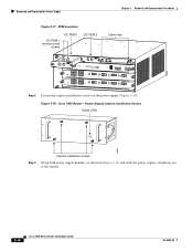
...Cisco 7606 Router-Power Supply Captive Installation Screws Status LEDs OUTPUT FAIL FAN OK INPUT OK 63895 Step 3 Captive installation screws Grasp both power supply handles, as shown in Figure 5-19, and slide the power supply completely out of the chassis. 5-16 Cisco 7600 Series Router Installation Guide OL-4503-24 Removing and Replacing... the Power Supply Chapter 5 Removal and Replacement Procedures Figure 5-17 PEM Locations DC PEM 1 terminal block...
...Cisco 7606 Router-Power Supply Captive Installation Screws Status LEDs OUTPUT FAIL FAN OK INPUT OK 63895 Step 3 Captive installation screws Grasp both power supply handles, as shown in Figure 5-19, and slide the power supply completely out of the chassis. 5-16 Cisco 7600 Series Router Installation Guide OL-4503-24 Removing and Replacing... the Power Supply Chapter 5 Removal and Replacement Procedures Figure 5-17 PEM Locations DC PEM 1 terminal block...

Installation Guide
Page 17
...DC circuit. Chapter 5 Removal and Replacement Procedures Removing and Replacing the Power Supply Figure 5-19 Cisco 7606 Router-Handling an DC-Input Power Supply OUTPUT FAIL FAN OK INPUT OK 63901 OUTPUT FAIL FAN OK INPUT OK Step 4 If the power supply bay is removed from a Cisco 7606 Router Warning Before performing any of... terminal block cover, and slide the cover off to the DC circuit connected to remain empty, install a blank power supply filler plate (Cisco part number 800-19193-01 for the Cisco 7606 router) over the opening and secure it with the captive installation screws.
...DC circuit. Chapter 5 Removal and Replacement Procedures Removing and Replacing the Power Supply Figure 5-19 Cisco 7606 Router-Handling an DC-Input Power Supply OUTPUT FAIL FAN OK INPUT OK 63901 OUTPUT FAIL FAN OK INPUT OK Step 4 If the power supply bay is removed from a Cisco 7606 Router Warning Before performing any of... terminal block cover, and slide the cover off to the DC circuit connected to remain empty, install a blank power supply filler plate (Cisco part number 800-19193-01 for the Cisco 7606 router) over the opening and secure it with the captive installation screws.

Installation Guide
Page 18
...Use both hands to install and remove power supplies. Each PWR-2700-DC DC-input power supply weighs 13.5 pounds (6.6 kg). 5-18 Cisco 7600 Series Router Installation Guide OL-4503-24 Warning When installing the unit, the ground connection must always be made first and disconnected last. ...Removing and Replacing the Power Supply Chapter 5 Removal and Replacement Procedures Figure 5-20 DC-Input Front Panel for 2700-W DC-Input Power Supply 1 2 3 PWR-2700-DC/6 -VE-1 -VE-1 ...
...Use both hands to install and remove power supplies. Each PWR-2700-DC DC-input power supply weighs 13.5 pounds (6.6 kg). 5-18 Cisco 7600 Series Router Installation Guide OL-4503-24 Warning When installing the unit, the ground connection must always be made first and disconnected last. ...Removing and Replacing the Power Supply Chapter 5 Removal and Replacement Procedures Figure 5-20 DC-Input Front Panel for 2700-W DC-Input Power Supply 1 2 3 PWR-2700-DC/6 -VE-1 -VE-1 ...

Installation Guide
Page 19
Chapter 5 Removal and Replacement Procedures Removing and Replacing the Power Supply Step 7 Grasp both power supply handles, as shown in...power is off the terminal block (Figure 5-22). Removing PWR-2700-DC Power Supply from a Cisco 7606-S Router Warning Before performing any of the following procedures, ensure that power is removed from the DC circuit. OL-4503-... slide the cover off to the DC circuit connected to remain empty, install a blank power supply filler plate (Cisco part number 700-03104-01) over the opening, and secure it with the captive installation screws. Figure 5-21 ...
Chapter 5 Removal and Replacement Procedures Removing and Replacing the Power Supply Step 7 Grasp both power supply handles, as shown in...power is off the terminal block (Figure 5-22). Removing PWR-2700-DC Power Supply from a Cisco 7606-S Router Warning Before performing any of the following procedures, ensure that power is removed from the DC circuit. OL-4503-... slide the cover off to the DC circuit connected to remain empty, install a blank power supply filler plate (Cisco part number 700-03104-01) over the opening, and secure it with the captive installation screws. Figure 5-21 ...

Installation Guide
Page 20
Each PWR-2700-DC DC-input power supply weighs 13.5 pounds (6.6 kg). 5-20 Cisco 7600 Series Router Installation Guide OL-4503-24 Removing and Replacing the Power Supply Chapter 5 Removal and Replacement Procedures Figure 5-22 DC-Input Front Panel for 2700-W DC-Input Power Supply 1 2 3 PWR-2700-DC/6 -VE-1 -VE-1 -VE-2 -VE-2 INPUT1 OK...
Each PWR-2700-DC DC-input power supply weighs 13.5 pounds (6.6 kg). 5-20 Cisco 7600 Series Router Installation Guide OL-4503-24 Removing and Replacing the Power Supply Chapter 5 Removal and Replacement Procedures Figure 5-22 DC-Input Front Panel for 2700-W DC-Input Power Supply 1 2 3 PWR-2700-DC/6 -VE-1 -VE-1 -VE-2 -VE-2 INPUT1 OK...

