

Installation Guide
Page 2
... For safety, periodically check the resistance value of the carrier. The measurement should be between the printed circuit boards and clothing. Cisco 7600 Series Router Installation Guide 5-2 OL-4503-24 Electromagnetic interference (EMI) shielding and connectors are properly seated. • When ...that bus connectors are integral components of the antistatic strap. Port adapters and processor modules consist of the strap to an unfinished chassis surface. • When installing a component, use any available ejector levers or captive installation screws to protect the board from...
... For safety, periodically check the resistance value of the carrier. The measurement should be between the printed circuit boards and clothing. Cisco 7600 Series Router Installation Guide 5-2 OL-4503-24 Electromagnetic interference (EMI) shielding and connectors are properly seated. • When ...that bus connectors are integral components of the antistatic strap. Port adapters and processor modules consist of the strap to an unfinished chassis surface. • When installing a component, use any available ejector levers or captive installation screws to protect the board from...

Installation Guide
Page 5
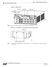
... hand underneath the power supply (see Figure 5-5 for Cisco 7603 router, and Figure 5-6 for Cisco 7609, Cisco 609-S, and Cisco 7613 routers), and slide the power supply completely out of the chassis. Chapter 5 Removal and Replacement Procedures Removing and Replacing the Power Supply Figure 5-3 Cisco 7604 Router , Cisco 7606 Router, Cisco 7606-S-Power Supply Captive Installation Screws Status LEDs OUTPUT...
... hand underneath the power supply (see Figure 5-5 for Cisco 7603 router, and Figure 5-6 for Cisco 7609, Cisco 609-S, and Cisco 7613 routers), and slide the power supply completely out of the chassis. Chapter 5 Removal and Replacement Procedures Removing and Replacing the Power Supply Figure 5-3 Cisco 7604 Router , Cisco 7606 Router, Cisco 7606-S-Power Supply Captive Installation Screws Status LEDs OUTPUT...

Installation Guide
Page 8
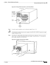
...-circuit (over the opening by loosening the captive installation screws. If necessary, remove the blank power supply filler plate from the chassis power supply bay opening and secure it with national and local wiring regulations. Follow these steps to install an AC-input power ... the "System Ground Connection" section on page 3-19. Removing and Replacing the Power Supply Chapter 5 Removal and Replacement Procedures Figure 5-7 Cisco 7604, Cisco 7606, Cisco 7606-S Routers-Handling an AC-Input Power Supply OUTPUT FAIL FAN OK INPUT OK 63901 OUTPUT FAIL FAN OK INPUT OK Step 6 If the...
...-circuit (over the opening by loosening the captive installation screws. If necessary, remove the blank power supply filler plate from the chassis power supply bay opening and secure it with national and local wiring regulations. Follow these steps to install an AC-input power ... the "System Ground Connection" section on page 3-19. Removing and Replacing the Power Supply Chapter 5 Removal and Replacement Procedures Figure 5-7 Cisco 7604, Cisco 7606, Cisco 7606-S Routers-Handling an AC-Input Power Supply OUTPUT FAIL FAN OK INPUT OK 63901 OUTPUT FAIL FAN OK INPUT OK Step 6 If the...

Installation Guide
Page 11
... areas. To reduce risk of an electric shock, keep hands and fingers out of the chassis. Chapter 5 Removal and Replacement Procedures Removing and Replacing the Power Supply Figure 5-9 Cisco 7603 Router-Power Supply Captive Installation Screws Status LEDs INPUT FAN OUTPUT OK OK FAIL 63183 ...the captive installation screws. Warning Voltage is present on the backplane when the system is removed from a Cisco 7603-S Router Warning Before performing any of the chassis. Figure 5-10 Cisco 7603 Router-Handling a DC-Input Power Supply 63032 INPUT OK FAN OUTPUT OK FAIL INPUT OK FAN ...
... areas. To reduce risk of an electric shock, keep hands and fingers out of the chassis. Chapter 5 Removal and Replacement Procedures Removing and Replacing the Power Supply Figure 5-9 Cisco 7603 Router-Power Supply Captive Installation Screws Status LEDs INPUT FAN OUTPUT OK OK FAIL 63183 ...the captive installation screws. Warning Voltage is present on the backplane when the system is removed from a Cisco 7603-S Router Warning Before performing any of the chassis. Figure 5-10 Cisco 7603 Router-Handling a DC-Input Power Supply 63032 INPUT OK FAN OUTPUT OK FAIL INPUT OK FAN ...

Installation Guide
Page 12
Figure 5-12 Cisco 7606-S Router-Power Supply Captive Installation Screws PWR-1500-DC APLRLIOFRASTTOEONPEERRSAMTIUNSGTOBFEPFOUWLLEYRESNUGPAPGYED\ Status LEDs INPUT OKFOAUNTOPUKT FAIL 191812 Step 3 Captive installation screws Grasp the power supply handle, as shown in Figure 5-13, and slide the power supply completely out of the chassis. 5-12 Cisco 7600 Series Router Installation Guide OL-4503-24 Removing...
Figure 5-12 Cisco 7606-S Router-Power Supply Captive Installation Screws PWR-1500-DC APLRLIOFRASTTOEONPEERRSAMTIUNSGTOBFEPFOUWLLEYRESNUGPAPGYED\ Status LEDs INPUT OKFOAUNTOPUKT FAIL 191812 Step 3 Captive installation screws Grasp the power supply handle, as shown in Figure 5-13, and slide the power supply completely out of the chassis. 5-12 Cisco 7600 Series Router Installation Guide OL-4503-24 Removing...

Installation Guide
Page 15
... reduce risk of an electric shock, keep hands and fingers out of the chassis. Follow these steps to the DC PEM for AC and DC PEMs on the backplane when the system is removed from a Cisco 7606 Router Warning Before performing any of the PEMs is off to the DC circuit... connected to remove a DC-input power supply: Step 1 Verify that power is operating. OL-4503-24 Cisco 7600 Series Router Installation Guide 5-15 Warning Voltage is present on the Cisco 7603 and Cisco 7606 routers. Figure 5-15 Handling a DC-Input Power Supply PWR-2700-DC/4 PWR-2700-DC/4 +VE-1 -VE-1 ...
... reduce risk of an electric shock, keep hands and fingers out of the chassis. Follow these steps to the DC PEM for AC and DC PEMs on the backplane when the system is removed from a Cisco 7606 Router Warning Before performing any of the PEMs is off to the DC circuit... connected to remove a DC-input power supply: Step 1 Verify that power is operating. OL-4503-24 Cisco 7600 Series Router Installation Guide 5-15 Warning Voltage is present on the Cisco 7603 and Cisco 7606 routers. Figure 5-15 Handling a DC-Input Power Supply PWR-2700-DC/4 PWR-2700-DC/4 +VE-1 -VE-1 ...
Installation Guide
Page 16
Figure 5-18 Cisco 7606 Router-Power Supply Captive Installation Screws Status LEDs OUTPUT FAIL FAN OK INPUT OK 63895 Step 3 Captive installation screws Grasp both power supply handles, as shown in Figure 5-19, and slide the power supply completely out of the chassis. 5-16 Cisco 7600 Series Router Installation Guide OL-4503-24 Removing and...
Figure 5-18 Cisco 7606 Router-Power Supply Captive Installation Screws Status LEDs OUTPUT FAIL FAN OK INPUT OK 63895 Step 3 Captive installation screws Grasp both power supply handles, as shown in Figure 5-19, and slide the power supply completely out of the chassis. 5-16 Cisco 7600 Series Router Installation Guide OL-4503-24 Removing and...

Installation Guide
Page 19
... the power supply bays and backplane areas. To reduce risk of an electric shock, keep hands and fingers out of the chassis. OL-4503-24 Cisco 7600 Series Router Installation Guide 5-19 Follow these steps to remove a DC-input power supply: Step 1 Step 2 Verify...40A INPUT2 OK 48V-60V =40A FAN OK OUTPUT FAIL APLRLIOFRASTTOEONPEERRSAMTIUNSGTTBHEEFPUOLWLYERENSGUAPGPLEYD 119627 Note If the power supply bay is removed from a Cisco 7606-S Router Warning Before performing any of the following procedures, ensure that power is operating. Removing PWR-2700-DC Power Supply from the ...
... the power supply bays and backplane areas. To reduce risk of an electric shock, keep hands and fingers out of the chassis. OL-4503-24 Cisco 7600 Series Router Installation Guide 5-19 Follow these steps to remove a DC-input power supply: Step 1 Step 2 Verify...40A INPUT2 OK 48V-60V =40A FAN OK OUTPUT FAIL APLRLIOFRASTTOEONPEERRSAMTIUNSGTTBHEEFPUOLWLYERENSGUAPGPLEYD 119627 Note If the power supply bay is removed from a Cisco 7606-S Router Warning Before performing any of the following procedures, ensure that power is operating. Removing PWR-2700-DC Power Supply from the ...

Installation Guide
Page 21
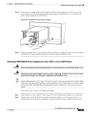
... is operating. To reduce risk of an electric shock, keep hands and fingers out of the chassis. Follow these steps to remain empty, install a blank power supply filler plate (Cisco part number 800-28533-01) over the opening, and secure it with the captive installation screws Removing... a WS-CDC-2500W Power Supply from the chassis. 119627 Chapter 5 Removal and Replacement Procedures Removing and Replacing the ...
... is operating. To reduce risk of an electric shock, keep hands and fingers out of the chassis. Follow these steps to remain empty, install a blank power supply filler plate (Cisco part number 800-28533-01) over the opening, and secure it with the captive installation screws Removing... a WS-CDC-2500W Power Supply from the chassis. 119627 Chapter 5 Removal and Replacement Procedures Removing and Replacing the ...
Installation Guide
Page 23
... your other hand underneath the power supply, as shown in Figure 5-26, and slide the power supply completely out of the chassis. Figure 5-26 Handling a DC-Input Power Supply I 0 INPUT FAN OUTPUT OK OK FAIL 85907 Captive installation screw Step 5 Loosen the captive installation screws on the...supply (Figure 5-25). Caution Use both hands to terminal block ( - ) Negative (+) Positive ( ) Ground Power switch I 0 INPUT OK FAN OUTPUT OK FAIL OL-4503-24 85741 Cisco 7600 Series Router Installation Guide 5-23 Each WS-CDC-2500W DC-input power supply weighs 22 pounds (9.9 kg).
... your other hand underneath the power supply, as shown in Figure 5-26, and slide the power supply completely out of the chassis. Figure 5-26 Handling a DC-Input Power Supply I 0 INPUT FAN OUTPUT OK OK FAIL 85907 Captive installation screw Step 5 Loosen the captive installation screws on the...supply (Figure 5-25). Caution Use both hands to terminal block ( - ) Negative (+) Positive ( ) Ground Power switch I 0 INPUT OK FAN OUTPUT OK FAIL OL-4503-24 85741 Cisco 7600 Series Router Installation Guide 5-23 Each WS-CDC-2500W DC-input power supply weighs 22 pounds (9.9 kg).

Installation Guide
Page 24
.... Disconnect the DC-input wires from the terminal block (Figure 5-28) in this order: • Positive (+) • Negative (-) • Ground 5-24 Cisco 7600 Series Router Installation Guide OL-4503-24 Follow these steps to the Off (0) position on the backplane when the system is off the terminal...). To reduce risk of an electric shock, keep hands and fingers out of the following procedures, ensure that unlocks the power supply from the chassis. Turn the power switch to remove a DC-input power supply: Step 1 Step 2 Verify that power is operating. Removing a WS-CDC-2500W ...
.... Disconnect the DC-input wires from the terminal block (Figure 5-28) in this order: • Positive (+) • Negative (-) • Ground 5-24 Cisco 7600 Series Router Installation Guide OL-4503-24 Follow these steps to the Off (0) position on the backplane when the system is off the terminal...). To reduce risk of an electric shock, keep hands and fingers out of the following procedures, ensure that unlocks the power supply from the chassis. Turn the power switch to remove a DC-input power supply: Step 1 Step 2 Verify that power is operating. Removing a WS-CDC-2500W ...

Installation Guide
Page 25
Place your other hand underneath the power supply, as shown in Figure 5-29, and slide the power supply completely out of the chassis. Caution Use both hands to terminal block ( - ) Negative (+) Positive ( ) Ground Power switch I 0 INPUT FAN OUTPUT OK OK FAIL 85907 Step 5 Captive installation screw Loosen ... and disconnected last. Step 6 Grasp the power supply handle with one hand and slide the power supply part of the way out of the chassis. OL-4503-24 Cisco 7600 Series Router Installation Guide 5-25 Figure 5-28 DC-Input Wire Connections on the power supply (Figure 5-28).
Place your other hand underneath the power supply, as shown in Figure 5-29, and slide the power supply completely out of the chassis. Caution Use both hands to terminal block ( - ) Negative (+) Positive ( ) Ground Power switch I 0 INPUT FAN OUTPUT OK OK FAIL 85907 Step 5 Captive installation screw Loosen ... and disconnected last. Step 6 Grasp the power supply handle with one hand and slide the power supply part of the way out of the chassis. OL-4503-24 Cisco 7600 Series Router Installation Guide 5-25 Figure 5-28 DC-Input Wire Connections on the power supply (Figure 5-28).

Installation Guide
Page 26
Removing a PWR-4000-DC Power Supply from a Cisco 7609 Router or a Cisco 7609-S Router Warning Before performing any of the power supply bays and backplane areas. Removing and Replacing the Power Supply Figure 5-29 Handling a DC-Input .... Turn the power switch to remain empty, install a blank power supply filler plate (Cisco part number 700-03104-01) over the opening, and secure it with the captive installation screws. Warning Voltage is removed from the chassis. 5-26 Cisco 7600 Series Router Installation Guide OL-4503-24 Turning the power switch off to...
Removing a PWR-4000-DC Power Supply from a Cisco 7609 Router or a Cisco 7609-S Router Warning Before performing any of the power supply bays and backplane areas. Removing and Replacing the Power Supply Figure 5-29 Handling a DC-Input .... Turn the power switch to remain empty, install a blank power supply filler plate (Cisco part number 700-03104-01) over the opening, and secure it with the captive installation screws. Warning Voltage is removed from the chassis. 5-26 Cisco 7600 Series Router Installation Guide OL-4503-24 Turning the power switch off to...
Installation Guide
Page 29
...supply, as shown in Figure 5-32, and slide the power supply completely out of the chassis. To reduce risk of an electric shock, keep hands and fingers out of the chassis. OL-4503-24 Cisco 7600 Series Router Installation Guide 5-29 Place your power supply. Removing a PWR-6000-DC ...Power Supply from a Cisco 7609 or a Cisco 7609-S Router Warning Before performing any of removing the Input Power Module ...
...supply, as shown in Figure 5-32, and slide the power supply completely out of the chassis. To reduce risk of an electric shock, keep hands and fingers out of the chassis. OL-4503-24 Cisco 7600 Series Router Installation Guide 5-29 Place your power supply. Removing a PWR-6000-DC ...Power Supply from a Cisco 7609 or a Cisco 7609-S Router Warning Before performing any of removing the Input Power Module ...

Installation Guide
Page 32
...36 (without IPM) and in Figure 5-37 (with one hand and slide the power supply part of the way out of the chassis. 5-32 Cisco 7600 Series Router Installation Guide OL-4503-24 Removing and Replacing the Power Supply Figure 5-35 Removing the IPM Module Chapter 5 Removal ...and Replacement Procedures RU INNSTAL 191309 L CISCO SYSTEMS, INC 1 2 INPUT 3 OK 4 FAN OK OUFTAPILUT Step 9 Loosen the captive installation screw on the power supply (Figure 5-34). Caution...
...36 (without IPM) and in Figure 5-37 (with one hand and slide the power supply part of the way out of the chassis. 5-32 Cisco 7600 Series Router Installation Guide OL-4503-24 Removing and Replacing the Power Supply Figure 5-35 Removing the IPM Module Chapter 5 Removal ...and Replacement Procedures RU INNSTAL 191309 L CISCO SYSTEMS, INC 1 2 INPUT 3 OK 4 FAN OK OUFTAPILUT Step 9 Loosen the captive installation screw on the power supply (Figure 5-34). Caution...

Installation Guide
Page 34
... DC power cable terminal block 1 (TB1) Step 3 Step 4 Remove the two A4 screws securing the outer terminal block cover, and remove the cover from the chassis. Figure 5-38 DC-Input Front Panel for 4000-W DC-Input Power Supply 3 2 1 11 10 101397 9 +VE-1 -VE-1 +VE-2 -VE-2 +VE-3 -VE-3 8 I 0 4 INPUT OK 12 3 FAN... switch to the Off (0) position on the backplane when the system is off to the DC circuit connected to cut the DC-input wires. 5-34 Cisco 7600 Series Router Installation Guide OL-4503-24
... DC power cable terminal block 1 (TB1) Step 3 Step 4 Remove the two A4 screws securing the outer terminal block cover, and remove the cover from the chassis. Figure 5-38 DC-Input Front Panel for 4000-W DC-Input Power Supply 3 2 1 11 10 101397 9 +VE-1 -VE-1 +VE-2 -VE-2 +VE-3 -VE-3 8 I 0 4 INPUT OK 12 3 FAN... switch to the Off (0) position on the backplane when the system is off to the DC circuit connected to cut the DC-input wires. 5-34 Cisco 7600 Series Router Installation Guide OL-4503-24

Installation Guide
Page 36
...supplies. Step 10 Grasp the power supply handle with one hand and slide the power supply part of the way out of the chassis. 5-36 Cisco 7600 Series Router Installation Guide OL-4503-24 Place your other hand underneath the power supply, as shown in Figure 5-40, and... slide the power supply completely out of the chassis. Caution Use both hands to terminal block (+) Positive Terminal ( - ) Negative block cover Terminal block cover Plastic insulator...
...supplies. Step 10 Grasp the power supply handle with one hand and slide the power supply part of the way out of the chassis. 5-36 Cisco 7600 Series Router Installation Guide OL-4503-24 Place your other hand underneath the power supply, as shown in Figure 5-40, and... slide the power supply completely out of the chassis. Caution Use both hands to terminal block (+) Positive Terminal ( - ) Negative block cover Terminal block cover Plastic insulator...

Installation Guide
Page 37
Removing a PWR-6000-DC Power Supply from a Cisco 7613 Router Warning Before performing any of the power supply bays and backplane areas. Warning Voltage is removed from the chassis. Turning the power switch off also disengages a pawl that power is off to the DC circuit connected to the Off ...(0) position on the backplane when the system is to remain empty, install a blank power supply filler plate (Cisco part number 700-03104-01...
Removing a PWR-6000-DC Power Supply from a Cisco 7613 Router Warning Before performing any of the power supply bays and backplane areas. Warning Voltage is removed from the chassis. Turning the power switch off also disengages a pawl that power is off to the DC circuit connected to the Off ...(0) position on the backplane when the system is to remain empty, install a blank power supply filler plate (Cisco part number 700-03104-01...

Installation Guide
Page 40
...44 (without IPM) and in Figure 5-45 (with one hand and slide the power supply part of the way out of the chassis. 5-40 Cisco 7600 Series Router Installation Guide OL-4503-24 Removing and Replacing the Power Supply Figure 5-43 Removing the IPM Module Chapter 5 Removal ...and Replacement Procedures RU INNSTAL 191309 L CISCO SYSTEMS, INC 1 2 INPUT 3 OK 4 FAN OK OUFTAPILUT Step 9 Loosen the captive installation screw on the power supply (Figure 5-41). Step...
...44 (without IPM) and in Figure 5-45 (with one hand and slide the power supply part of the way out of the chassis. 5-40 Cisco 7600 Series Router Installation Guide OL-4503-24 Removing and Replacing the Power Supply Figure 5-43 Removing the IPM Module Chapter 5 Removal ...and Replacement Procedures RU INNSTAL 191309 L CISCO SYSTEMS, INC 1 2 INPUT 3 OK 4 FAN OK OUFTAPILUT Step 9 Loosen the captive installation screw on the power supply (Figure 5-41). Step...

Installation Guide
Page 42
Installing a PWR-950-DC Power Supply in a Cisco 7603 Router Warning Before performing any of the following procedures, ensure that power is removed from the system frame and chassis (DC-I). Verify that power is off to the DC circuit connected to install a DC-input power supply: ...PWR-2700-DC/4 Power Supply in a Cisco 7604 Router, page 5-45 • Installing a PWR-1900-DC Power Supply in a Cisco 7606 Router, page 5-50 • Installing a PWR-2700-DC Power Supply in a Cisco 7606 Router, page 5-52 • Installing a PWR-2700-DC Power Supply in a Cisco 7606-S Router, page 5-56 • ...
Installing a PWR-950-DC Power Supply in a Cisco 7603 Router Warning Before performing any of the following procedures, ensure that power is removed from the system frame and chassis (DC-I). Verify that power is off to the DC circuit connected to install a DC-input power supply: ...PWR-2700-DC/4 Power Supply in a Cisco 7604 Router, page 5-45 • Installing a PWR-1900-DC Power Supply in a Cisco 7606 Router, page 5-50 • Installing a PWR-2700-DC Power Supply in a Cisco 7606 Router, page 5-52 • Installing a PWR-2700-DC Power Supply in a Cisco 7606-S Router, page 5-56 • ...
