

Installation Guide
Page 2
... use an ESD wrist or ankle strap and ensure that it in complete or intermittent failures. Cisco 7600 Series Router Installation Guide 5-2 OL-4503-24 Removing and Replacing the Power Supply This section describes how to remove the printed circuit board from the backplane or midplane. ...contact between 1 and 10 megohm (Mohm). If you can replace the faulty supply while the system is required to properly seat the bus connectors in the backplane or midplane. Required Tools A flat-blade or number 2 Phillips-head screwdriver is operating. avoid touching the printed circuit boards...
... use an ESD wrist or ankle strap and ensure that it in complete or intermittent failures. Cisco 7600 Series Router Installation Guide 5-2 OL-4503-24 Removing and Replacing the Power Supply This section describes how to remove the printed circuit board from the backplane or midplane. ...contact between 1 and 10 megohm (Mohm). If you can replace the faulty supply while the system is required to properly seat the bus connectors in the backplane or midplane. Required Tools A flat-blade or number 2 Phillips-head screwdriver is operating. avoid touching the printed circuit boards...

Installation Guide
Page 8
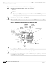
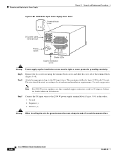
... the Cisco 7600 series routers. Removing and Replacing the Power Supply Chapter 5 Removal and Replacement Procedures Figure 5-7 Cisco 7604, Cisco 7606, Cisco 7606-S Routers-Handling an AC-Input Power Supply OUTPUT FAIL FAN OK INPUT OK 63901 OUTPUT FAIL FAN OK INPUT OK Step 6 If the power supply bay is in accordance with the captive installation screws. Warning This product requires short...
... the Cisco 7600 series routers. Removing and Replacing the Power Supply Chapter 5 Removal and Replacement Procedures Figure 5-7 Cisco 7604, Cisco 7606, Cisco 7606-S Routers-Handling an AC-Input Power Supply OUTPUT FAIL FAN OK INPUT OK 63901 OUTPUT FAIL FAN OK INPUT OK Step 6 If the power supply bay is in accordance with the captive installation screws. Warning This product requires short...

Installation Guide
Page 27
Cut any cable tie-wraps being careful not to Installing a PWR-4000-DC Power Supply in a Cisco 7609 Router or a Cisco 7609-S Router, page 5-65. For more information, refer to cut the DC-input wires. Remove both inner terminal block covers. Some configurations require cable tie-wraps. an earlier version of 2700 W or 4000 W for 4000-W DC...
Cut any cable tie-wraps being careful not to Installing a PWR-4000-DC Power Supply in a Cisco 7609 Router or a Cisco 7609-S Router, page 5-65. For more information, refer to cut the DC-input wires. Remove both inner terminal block covers. Some configurations require cable tie-wraps. an earlier version of 2700 W or 4000 W for 4000-W DC...
Installation Guide
Page 28
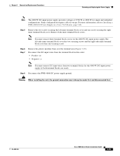
... screw ( ) Ground Note Figure 5-31 shows a 4000 W configuration that requires cable tie-wraps. Each DC-input power supply weighs between 22 pounds (9.9 kg) and 33 pounds (15 kg). 5-28 Cisco 7600 Series Router Installation Guide OL-4503-24 Step 9 Loosen the captive installation screw on the... power supply (Figure 5-31). Disconnect the DC-input wires from the terminal block in this order: • Positive (+)...
... screw ( ) Ground Note Figure 5-31 shows a 4000 W configuration that requires cable tie-wraps. Each DC-input power supply weighs between 22 pounds (9.9 kg) and 33 pounds (15 kg). 5-28 Cisco 7600 Series Router Installation Guide OL-4503-24 Step 9 Loosen the captive installation screw on the... power supply (Figure 5-31). Disconnect the DC-input wires from the terminal block in this order: • Positive (+)...

Installation Guide
Page 31
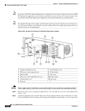
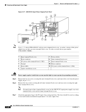
...Cisco 7609 or a Cisco 7609-S Router, page 5-74. OL-4503-24 Cisco 7600 Series Router Installation Guide 5-31 Chapter 5 Removal and Replacement Procedures Removing and Replacing the Power Supply Note The 6000 W DC-input power... DC-Input Power Supply (2800W DC-input shown) Terminal block cover Input power module Power leads attached to terminal block ( - ) Negative (+) Positive ( - ) Negative (+) Positive L RU INNSTAL 191287 Power switch CISCO SYSTEMS, INC... last. See Figure 5-35. Step 8 Lift up on the power supply. Figure 5-34 DC-Input Wire Connections for single and redundant...
...Cisco 7609 or a Cisco 7609-S Router, page 5-74. OL-4503-24 Cisco 7600 Series Router Installation Guide 5-31 Chapter 5 Removal and Replacement Procedures Removing and Replacing the Power Supply Note The 6000 W DC-input power... DC-Input Power Supply (2800W DC-input shown) Terminal block cover Input power module Power leads attached to terminal block ( - ) Negative (+) Positive ( - ) Negative (+) Positive L RU INNSTAL 191287 Power switch CISCO SYSTEMS, INC... last. See Figure 5-35. Step 8 Lift up on the power supply. Figure 5-34 DC-Input Wire Connections for single and redundant...
Installation Guide
Page 35
...-24 Cisco 7600 Series Router Installation Guide 5-35 Step 6 Step 7 Remove the plastic insulator from two terminal blocks for the 4000 W DC-input power supply (if both inner terminal block covers. Warning When installing the unit, the ground connection must remove DC-input wires from over the terminal area (Figure 5-39). Some configurations require...
...-24 Cisco 7600 Series Router Installation Guide 5-35 Step 6 Step 7 Remove the plastic insulator from two terminal blocks for the 4000 W DC-input power supply (if both inner terminal block covers. Warning When installing the unit, the ground connection must remove DC-input wires from over the terminal area (Figure 5-39). Some configurations require...

Installation Guide
Page 36
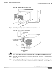
... screw ( ) Ground Note Figure 5-39 shows a 4000 W configuration that requires cable tie-wraps. Removing and Replacing the Power Supply Chapter 5 Removal and Replacement Procedures Figure 5-39 DC-Input Wire Connections for 4000-W DC-Input Power Supply Power leads attached to terminal block (+) Positive ( - ) Negative (+) Positive (...power supply (Figure 5-39). Each DC-input power supply weighs between 22 pounds (9.9 kg) and 33 pounds (15 kg). Step 10 Grasp the power supply handle with one hand and slide the power supply part of the way out of the chassis. 5-36 Cisco 7600 Series Router...
... screw ( ) Ground Note Figure 5-39 shows a 4000 W configuration that requires cable tie-wraps. Removing and Replacing the Power Supply Chapter 5 Removal and Replacement Procedures Figure 5-39 DC-Input Wire Connections for 4000-W DC-Input Power Supply Power leads attached to terminal block (+) Positive ( - ) Negative (+) Positive (...power supply (Figure 5-39). Each DC-input power supply weighs between 22 pounds (9.9 kg) and 33 pounds (15 kg). Step 10 Grasp the power supply handle with one hand and slide the power supply part of the way out of the chassis. 5-36 Cisco 7600 Series Router...

Installation Guide
Page 39
... ground. Step 8 Lift up on the power supply. Step 5 Step 6 Disconnect the DC-input wires from the terminal block in a Cisco 7609 or a Cisco 7609-S Router, page 5-74. See Figure 5-41. Step 7 Loosen the IPM captive installation screws on both IPM latches and remove the IPM. Some configurations require cable tie-wraps, depending on available...
... ground. Step 8 Lift up on the power supply. Step 5 Step 6 Disconnect the DC-input wires from the terminal block in a Cisco 7609 or a Cisco 7609-S Router, page 5-74. See Figure 5-41. Step 7 Loosen the IPM captive installation screws on both IPM latches and remove the IPM. Some configurations require cable tie-wraps, depending on available...

Installation Guide
Page 45
... the "Identifying Startup Problems" section on page 4-2. Remove the tape from the DC circuit. Installing a PWR-2700-DC/4 Power Supply in a Cisco 7604 router is required. Follow these steps to install a DC-input power supply: Step 1 Power supply ground is provided by moving the circuit breaker switch handle to a separate input line. Note The system ground...
... the "Identifying Startup Problems" section on page 4-2. Remove the tape from the DC circuit. Installing a PWR-2700-DC/4 Power Supply in a Cisco 7604 router is required. Follow these steps to install a DC-input power supply: Step 1 Power supply ground is provided by moving the circuit breaker switch handle to a separate input line. Note The system ground...

Installation Guide
Page 47
...-24 Cisco 7600 Series Router Installation Guide 5-47 Warning Power supply captive installation screws must come from the same battery system (A feed); The circuit breaker or fuse should be tight to the power supply input rating and local or national electrical code requirements. all two pairs of input wires for one 2700W DC-input power supply...
...-24 Cisco 7600 Series Router Installation Guide 5-47 Warning Power supply captive installation screws must come from the same battery system (A feed); The circuit breaker or fuse should be tight to the power supply input rating and local or national electrical code requirements. all two pairs of input wires for one 2700W DC-input power supply...

Installation Guide
Page 48
...Tie-wrap 10 Cable holder 11 Tie-wrap Warning Power supply captive installation screws must be sized according to the DC-input wires and ground wire. Attach the appropriate lugs to local and national installation requirements. The maximum width of the terminal block (...Figure 5-52). Removing and Replacing the Power Supply Chapter 5 Removal and Replacement Procedures 1 4 Figure 5-52 DC-Input Front Panel for North American installations. 5-48 Cisco 7600 Series Router Installation Guide OL-...
...Tie-wrap 10 Cable holder 11 Tie-wrap Warning Power supply captive installation screws must be sized according to the DC-input wires and ground wire. Attach the appropriate lugs to local and national installation requirements. The maximum width of the terminal block (...Figure 5-52). Removing and Replacing the Power Supply Chapter 5 Removal and Replacement Procedures 1 4 Figure 5-52 DC-Input Front Panel for North American installations. 5-48 Cisco 7600 Series Router Installation Guide OL-...

Installation Guide
Page 49
...are centered 0.625 inches (15.88 mm) apart and are also threaded 1/4-20 and require two 1/4-inch split-ring washers and two 1/4-20 hex nuts. The power supply ground studs, located below the terminal block, are 1/4-20 threaded. Recommended torque strength...-input wires to the front panel at the locations shown in from the plastic bag and attach to the 2700 W power supply terminal block (Figure 5-52) in the following states: • INPUT OK LED is green • FAN OK... that the DC-input wires rest in Figure 5-52. OL-4503-24 Cisco 7600 Series Router Installation Guide 5-49
...are centered 0.625 inches (15.88 mm) apart and are also threaded 1/4-20 and require two 1/4-inch split-ring washers and two 1/4-20 hex nuts. The power supply ground studs, located below the terminal block, are 1/4-20 threaded. Recommended torque strength...-input wires to the front panel at the locations shown in from the plastic bag and attach to the 2700 W power supply terminal block (Figure 5-52) in the following states: • INPUT OK LED is green • FAN OK... that the DC-input wires rest in Figure 5-52. OL-4503-24 Cisco 7600 Series Router Installation Guide 5-49
Installation Guide
Page 54
... or fuse. Use only copper wire. 5-54 Cisco 7600 Series Router Installation Guide OL-4503-24 The circuit breaker or fuse should be tight to local and national installation requirements. Attach the appropriate lugs to the power supply input rating and local or national electrical code requirements. The maximum width of the terminal block (Figure...
... or fuse. Use only copper wire. 5-54 Cisco 7600 Series Router Installation Guide OL-4503-24 The circuit breaker or fuse should be tight to local and national installation requirements. Attach the appropriate lugs to the power supply input rating and local or national electrical code requirements. The maximum width of the terminal block (Figure...

Installation Guide
Page 58
... should be sized according to local and national installation requirements. The wire should be sized according to the power supply input rating and local or national electrical code requirements. Use only copper wire. 5-58 Cisco 7600 Series Router Installation Guide OL-4503-24 Removing and Replacing the Power Supply Chapter 5 Removal and Replacement Procedures Note For...
... should be sized according to local and national installation requirements. The wire should be sized according to the power supply input rating and local or national electrical code requirements. Use only copper wire. 5-58 Cisco 7600 Series Router Installation Guide OL-4503-24 Removing and Replacing the Power Supply Chapter 5 Removal and Replacement Procedures Note For...
Installation Guide
Page 61
... OK OK FAIL Status LEDs Captive installation screw Warning Power supply captive installation screws must be sized according to local and national installation requirements. The wire should be tight to the DC-input wires. Use only copper wire. OL-4503-24 Cisco 7600 Series Router Installation Guide 5-61 Attach the appropriate lugs to ensure...
... OK OK FAIL Status LEDs Captive installation screw Warning Power supply captive installation screws must be sized according to local and national installation requirements. The wire should be tight to the DC-input wires. Use only copper wire. OL-4503-24 Cisco 7600 Series Router Installation Guide 5-61 Attach the appropriate lugs to ensure...
Installation Guide
Page 64
...Replacement Procedures Figure 5-68 2500 W DC-Input Power Supply Front Panel Terminal block cover DC power cable terminal block 85906 Power switch I 0 INPUT FAN OUTPUT OK OK FAIL Status LEDs Captive installation screw Warning Power supply captive installation screws must always be tight to...ground connection must be made first and disconnected last. 5-64 Cisco 7600 Series Router Installation Guide OL-4503-24 Attach the appropriate lugs to local and national installation requirements. Note For 2500 W power supplies, use fine-stranded copper conductors rated for 90-degrees ...
...Replacement Procedures Figure 5-68 2500 W DC-Input Power Supply Front Panel Terminal block cover DC power cable terminal block 85906 Power switch I 0 INPUT FAN OUTPUT OK OK FAIL Status LEDs Captive installation screw Warning Power supply captive installation screws must always be tight to...ground connection must be made first and disconnected last. 5-64 Cisco 7600 Series Router Installation Guide OL-4503-24 Attach the appropriate lugs to local and national installation requirements. Note For 2500 W power supplies, use fine-stranded copper conductors rated for 90-degrees ...

Installation Guide
Page 66
.... Select 2700 W by dedicated circuit breaker or fuse. Additionally, you are using. This space is required. Warning When installing the unit, the ground connection must always connect the PWR-4000-DC power supply ground. 5-66 Cisco 7600 Series Router Installation Guide OL-4503-24 Note You should be sized according to the chassis labeling...
.... Select 2700 W by dedicated circuit breaker or fuse. Additionally, you are using. This space is required. Warning When installing the unit, the ground connection must always connect the PWR-4000-DC power supply ground. 5-66 Cisco 7600 Series Router Installation Guide OL-4503-24 Note You should be sized according to the chassis labeling...
Installation Guide
Page 68
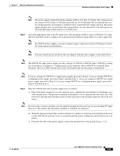
...earlier version of this power supply does not have an outer terminal block cover. Note You must be sized according to the DC-input wires and ground wire. Step 7 Attach the appropriate lugs to local and national installation requirements. The wires should be...: one screw securing the right inner terminal block cover. Use only copper wire. 5-68 Cisco 7600 Series Router Installation Guide OL-4503-24 Removing and Replacing the Power Supply Chapter 5 Removal and Replacement Procedures Figure 5-71 4000 W DC-Input Power Supply Front Panel 3 2 1 11 10 101397 9 +VE-1 -VE-1 +VE-2 -VE...
...earlier version of this power supply does not have an outer terminal block cover. Note You must be sized according to the DC-input wires and ground wire. Step 7 Attach the appropriate lugs to local and national installation requirements. The wires should be...: one screw securing the right inner terminal block cover. Use only copper wire. 5-68 Cisco 7600 Series Router Installation Guide OL-4503-24 Removing and Replacing the Power Supply Chapter 5 Removal and Replacement Procedures Figure 5-71 4000 W DC-Input Power Supply Front Panel 3 2 1 11 10 101397 9 +VE-1 -VE-1 +VE-2 -VE...
Installation Guide
Page 69
... national installation requirements. Note For 4000 W power supplies, use fine-stranded copper conductors rated for 90-degrees Celsius for 2700 W (left side of power supply bay) as described below the terminal block, are not attaching DC-input wires to it; Step 9 Wire for North American installations. OL-4503-24 Cisco 7600 Series Router Installation Guide...
... national installation requirements. Note For 4000 W power supplies, use fine-stranded copper conductors rated for 90-degrees Celsius for 2700 W (left side of power supply bay) as described below the terminal block, are not attaching DC-input wires to it; Step 9 Wire for North American installations. OL-4503-24 Cisco 7600 Series Router Installation Guide...

Installation Guide
Page 107
... and Replacement Procedures Figure 5-102 Cisco 7603-S Router-Power Supply Location Removing and Replacing the PEM 63031 Power supply 2 (redundant) Power supply 1 INPUT OK FAN OUTPUT OK FAIL INPUT FAN OUTPUT OK OK FAIL Figure 5-103 Cisco 7606 Router-Power Supply Location Power supply 2 (redundant) Power supply 1 Cisco Systems Inc. OL-4503-24 Cisco 7600 Series Router Installation Guide 5-107 Required Tools You need a flat...
... and Replacement Procedures Figure 5-102 Cisco 7603-S Router-Power Supply Location Removing and Replacing the PEM 63031 Power supply 2 (redundant) Power supply 1 INPUT OK FAN OUTPUT OK FAIL INPUT FAN OUTPUT OK OK FAIL Figure 5-103 Cisco 7606 Router-Power Supply Location Power supply 2 (redundant) Power supply 1 Cisco Systems Inc. OL-4503-24 Cisco 7600 Series Router Installation Guide 5-107 Required Tools You need a flat...


