

Installation Guide
Page 12
... 3 FAN-MOD-3SHS ETHERNET SERVICES MODULE STATUS 1 A/L STATUS 1 A/L CLASS 1 LASER CLASS 1 LASER Fan assembly -4580TAOM-A6X0V A/L 0 A/L 0 Step 2 Slots 1-3 (top to the DC PEM for the power supply you are removing (Figure 5-11). Figure 5-12 Cisco 7606-S Router-Power Supply Captive Installation Screws PWR-1500-DC APLRLIOFRASTTOEONPEERRSAMTIUNSGTOBFEPFOUWLLEYRESNUGPAPGYED\ Status LEDs INPUT OKFOAUNTOPUKT FAIL 191812 Step...
... 3 FAN-MOD-3SHS ETHERNET SERVICES MODULE STATUS 1 A/L STATUS 1 A/L CLASS 1 LASER CLASS 1 LASER Fan assembly -4580TAOM-A6X0V A/L 0 A/L 0 Step 2 Slots 1-3 (top to the DC PEM for the power supply you are removing (Figure 5-11). Figure 5-12 Cisco 7606-S Router-Power Supply Captive Installation Screws PWR-1500-DC APLRLIOFRASTTOEONPEERRSAMTIUNSGTOBFEPFOUWLLEYRESNUGPAPGYED\ Status LEDs INPUT OKFOAUNTOPUKT FAIL 191812 Step...
Installation Guide
Page 69
...redundant power supply, proceed to Step 9; Wrap the large perforated flaps around the power cabling trim and discard excess tab plastic. c. OL-4503-24 Cisco 7600 Series Router Installation Guide 5-69 The terminal posts are centered 0.625 inches (15.88 mm) apart and are shipped with terminal posts. If...inserting each locking tab into rear of the terminal (opposite side from wire entry). Note You must fold down and cover the open side of slot. Note The 4000 W DC-input power supply provides voltages of a lug is 0.62 inch (15.8 mm). if you use . this ensures...
...redundant power supply, proceed to Step 9; Wrap the large perforated flaps around the power cabling trim and discard excess tab plastic. c. OL-4503-24 Cisco 7600 Series Router Installation Guide 5-69 The terminal posts are centered 0.625 inches (15.88 mm) apart and are shipped with terminal posts. If...inserting each locking tab into rear of the terminal (opposite side from wire entry). Note You must fold down and cover the open side of slot. Note The 4000 W DC-input power supply provides voltages of a lug is 0.62 inch (15.8 mm). if you use . this ensures...

Installation Guide
Page 70
... ( - ) Negative Plastic insulator Terminal block cover 114010 ( ) Ground I 0 Power switch INPUT OK 12 3 FAN OUTPUT OK FAIL Captive installation screw d. Wire for Left Side of slot. The protective end flap on the plastic cover is 20 inch-pounds. b. From the left and right inner terminal block cover. Wrap the large perforated... for 2700-W DC-Input Power Supply for 4000 W (left side of the power supply, connect the DC-input wires to the ground (Figure 5-73). 5-70 Cisco 7600 Series Router Installation Guide OL-4503-24
... ( - ) Negative Plastic insulator Terminal block cover 114010 ( ) Ground I 0 Power switch INPUT OK 12 3 FAN OUTPUT OK FAIL Captive installation screw d. Wire for Left Side of slot. The protective end flap on the plastic cover is 20 inch-pounds. b. From the left and right inner terminal block cover. Wrap the large perforated... for 2700-W DC-Input Power Supply for 4000 W (left side of the power supply, connect the DC-input wires to the ground (Figure 5-73). 5-70 Cisco 7600 Series Router Installation Guide OL-4503-24

Installation Guide
Page 71
... nuts, make sure they are snug. h. Place both plastic insulators over tighten them. Using the cable tie provided, place the cable tie through the slot at the top of the left side of the power supply, connect the DC-input wires to TB2. The protective end flap on the plastic... cover is 20 inch-pounds. OL-4503-24 Cisco 7600 Series Router Installation Guide 5-71 From the left and right inner terminal block cover. Secure outer block cover. The protective end flap must fold...
... nuts, make sure they are snug. h. Place both plastic insulators over tighten them. Using the cable tie provided, place the cable tie through the slot at the top of the left side of the power supply, connect the DC-input wires to TB2. The protective end flap on the plastic... cover is 20 inch-pounds. OL-4503-24 Cisco 7600 Series Router Installation Guide 5-71 From the left and right inner terminal block cover. Secure outer block cover. The protective end flap must fold...

Installation Guide
Page 72
...inch-pounds. Recommended torque strength is opposite the wire entry area. f. Using the cable tie provided, place the cable tie through the slot at the top of slot. The protective end flap must fold down and cover the open side of power supply bay) as follows: a. Do not over ... for future use. c. Figure 5-74 DC-Input Wire Connections for 4000 W (right side of the terminal (opposite side from wire entry). 5-72 Cisco 7600 Series Router Installation Guide OL-4503-24 Over tightening the terminal nuts can break the terminal block (Maximum torque: 36 inch-pounds). b. From the...
...inch-pounds. Recommended torque strength is opposite the wire entry area. f. Using the cable tie provided, place the cable tie through the slot at the top of slot. The protective end flap must fold down and cover the open side of power supply bay) as follows: a. Do not over ... for future use. c. Figure 5-74 DC-Input Wire Connections for 4000 W (right side of the terminal (opposite side from wire entry). 5-72 Cisco 7600 Series Router Installation Guide OL-4503-24 Over tightening the terminal nuts can break the terminal block (Maximum torque: 36 inch-pounds). b. From the...

Installation Guide
Page 73
... slot. Do not over tighten them . Recommended torque strength is 20 inch-pounds. From the right side of the power supply, connect the DC-input wires to the ground (Figure 5-75). Do not over tighten them . Over tightening the terminal nuts can break the terminal block (Maximum torque: 36 inch-pounds). Cisco...
... slot. Do not over tighten them . Recommended torque strength is 20 inch-pounds. From the right side of the power supply, connect the DC-input wires to the ground (Figure 5-75). Do not over tighten them . Over tightening the terminal nuts can break the terminal block (Maximum torque: 36 inch-pounds). Cisco...

Installation Guide
Page 74
...pairs of installing an Input Power Module (IPM) (previously removed) with the DC-input wires and the ground wires still connected. Read through the slot at the top of the right terminal block cover and secure the wiring going to the power supply input rating and local or national electrical... code requirements. h. Step 13 Step 14 After confirming all installation steps are in a Cisco 7609 or a Cisco 7609-S Router Note With the PWR-6000-DC power supply, you have the option of input wires for the other 4000W DC-input power...
...pairs of installing an Input Power Module (IPM) (previously removed) with the DC-input wires and the ground wires still connected. Read through the slot at the top of the right terminal block cover and secure the wiring going to the power supply input rating and local or national electrical... code requirements. h. Step 13 Step 14 After confirming all installation steps are in a Cisco 7609 or a Cisco 7609-S Router Note With the PWR-6000-DC power supply, you have the option of input wires for the other 4000W DC-input power...

Installation Guide
Page 89
...terminal areas, aligning the circular holes in any sequence. b. Pull the tab until the cover is 0.300 inch (7.6 mm). OL-4503-24 Cisco 7600 Series Router Installation Guide 5-89 if you use an appropriately sized industry standard 2-hole, standard barrel compression lug. Place both plastic insulators ...inserting each locking tab into rear of the terminal (opposite side from wire entry). Note You must fold down and cover the open side of slot. Note For 4000 W power supplies, use . this ensures that are wiring 2700 W for a single power supply, proceed to it; Wrap ...
...terminal areas, aligning the circular holes in any sequence. b. Pull the tab until the cover is 0.300 inch (7.6 mm). OL-4503-24 Cisco 7600 Series Router Installation Guide 5-89 if you use an appropriately sized industry standard 2-hole, standard barrel compression lug. Place both plastic insulators ...inserting each locking tab into rear of the terminal (opposite side from wire entry). Note You must fold down and cover the open side of slot. Note For 4000 W power supplies, use . this ensures that are wiring 2700 W for a single power supply, proceed to it; Wrap ...

Installation Guide
Page 90
...2700-W DC-Input Power Supply for 4000 W (left side of the power supply, connect the DC-input wires to the ground (Figure 5-88). 5-90 Cisco 7600 Series Router Installation Guide OL-4503-24 Recommended torque strength is opposite the wire entry area. Place both plastic insulators over tighten them. Wrap... of power supply bay) as follows: a. From the left side of the terminal (opposite side from wire entry). Wire for Left Side of slot. From the left and right inner terminal block cover. e. The protective end flap on the plastic cover is 20 inch-pounds. c. b.
...2700-W DC-Input Power Supply for 4000 W (left side of the power supply, connect the DC-input wires to the ground (Figure 5-88). 5-90 Cisco 7600 Series Router Installation Guide OL-4503-24 Recommended torque strength is opposite the wire entry area. Place both plastic insulators over tighten them. Wrap... of power supply bay) as follows: a. From the left side of the terminal (opposite side from wire entry). Wire for Left Side of slot. From the left and right inner terminal block cover. e. The protective end flap on the plastic cover is 20 inch-pounds. c. b.

Installation Guide
Page 91
...insulator Power leads attached to TB2. Recommended torque strength is 20 inch-pounds. Using the cable tie provided, place the cable tie through the slot at the top of the left side of the power supply, connect the DC-input wires to TB1 in this order: Negative (-) Positive... torque: 36 inch-pounds). Over tightening the terminal nuts can break the terminal block (Maximum torque: 36 inch-pounds). h. OL-4503-24 Cisco 7600 Series Router Installation Guide 5-91 Do not over tighten them . Secure outer block cover. From the left terminal block cover and secure the...
...insulator Power leads attached to TB2. Recommended torque strength is 20 inch-pounds. Using the cable tie provided, place the cable tie through the slot at the top of the left side of the power supply, connect the DC-input wires to TB1 in this order: Negative (-) Positive... torque: 36 inch-pounds). Over tightening the terminal nuts can break the terminal block (Maximum torque: 36 inch-pounds). h. OL-4503-24 Cisco 7600 Series Router Installation Guide 5-91 Do not over tighten them . Secure outer block cover. From the left terminal block cover and secure the...

Installation Guide
Page 92
...The protective end flap on the plastic cover is 20 inch-pounds. The protective end flap must fold down and cover the open side of slot. this order: Negative (-) Positive (+) Note When you are snug. Recommended torque strength is opposite the wire entry area. e. b. Pull the... tab until the cover is available for future use. Secure outer block cover. 5-92 Cisco 7600 Series Router Installation Guide OL-4503-24 Wrap the large perforated flaps around the power cabling trim and discard excess tab plastic. c. From...
...The protective end flap on the plastic cover is 20 inch-pounds. The protective end flap must fold down and cover the open side of slot. this order: Negative (-) Positive (+) Note When you are snug. Recommended torque strength is opposite the wire entry area. e. b. Pull the... tab until the cover is available for future use. Secure outer block cover. 5-92 Cisco 7600 Series Router Installation Guide OL-4503-24 Wrap the large perforated flaps around the power cabling trim and discard excess tab plastic. c. From...

Installation Guide
Page 93
... ) Ground d. The protective end flap on the plastic cover is secured around each pair of conductors, inserting each locking tab into rear of slot. b. Pull the tab until the cover is opposite the wire entry area. Do not over the terminal areas, aligning the circular holes in ...insulating cover with terminal posts. Recommended torque strength is 20 inch-pounds. Cisco 7600 Series Router Installation Guide 5-93 From the right side of power supply bay) as follows: a. From the right side of the terminal...
... ) Ground d. The protective end flap on the plastic cover is secured around each pair of conductors, inserting each locking tab into rear of slot. b. Pull the tab until the cover is opposite the wire entry area. Do not over the terminal areas, aligning the circular holes in ...insulating cover with terminal posts. Recommended torque strength is 20 inch-pounds. Cisco 7600 Series Router Installation Guide 5-93 From the right side of power supply bay) as follows: a. From the right side of the terminal...

Installation Guide
Page 94
...Replacing the Power Supply Chapter 5 Removal and Replacement Procedures f. h. Read through the slot at the top of input wires for the other 4000W DC-input power supply must come from the DC circuit. 5-94 Cisco 7600 Series Router Installation Guide OL-4503-24 Place and secure left terminal block....g. The circuit breaker or fuse should be made first and disconnected last. Step 12 Step 13 After confirming all installation steps are in a Cisco 7613 Router Note With the PWR-6000-DC power supply, you have the option of the following states: • INPUT OK LED is green...
...Replacing the Power Supply Chapter 5 Removal and Replacement Procedures f. h. Read through the slot at the top of input wires for the other 4000W DC-input power supply must come from the DC circuit. 5-94 Cisco 7600 Series Router Installation Guide OL-4503-24 Place and secure left terminal block....g. The circuit breaker or fuse should be made first and disconnected last. Step 12 Step 13 After confirming all installation steps are in a Cisco 7613 Router Note With the PWR-6000-DC power supply, you have the option of the following states: • INPUT OK LED is green...

Installation Guide
Page 127
Figure 5-129 Thermistor Module 1 2 191354 3 1 Thermistor slots 3 Flange 2 Captive screw Step 3 Grasp the flange on a Cisco 7609-S Router TX PORT 2 PORT 2 191353 Step 2 Unscrew the single captive screw that retains the thermistor module in the chassis. See Figure 5-130. See Figure 5-... RX ACTIVE TX RX Installing the Thermistor Module on the thermistor module (see Figure 5-129) and pull to remove the thermistor module. OL-4503-24 Cisco 7600 Series Router Installation Guide 5-127
Figure 5-129 Thermistor Module 1 2 191354 3 1 Thermistor slots 3 Flange 2 Captive screw Step 3 Grasp the flange on a Cisco 7609-S Router TX PORT 2 PORT 2 191353 Step 2 Unscrew the single captive screw that retains the thermistor module in the chassis. See Figure 5-130. See Figure 5-... RX ACTIVE TX RX Installing the Thermistor Module on the thermistor module (see Figure 5-129) and pull to remove the thermistor module. OL-4503-24 Cisco 7600 Series Router Installation Guide 5-127

User Guide
Page 20
... in the management system before actual installation. Cisco 6500/7600 Series Manager User Guide 1-2 These high-performance, modular, frame-based switches support high-density Fast Ethernet and Gigabit Ethernet in Figure 1-1), and the 13-slot 6513 switch. Catalyst 6000 Family Overview Chapter ...1 Product Overview Software Features The C65/76M software provides the following features: • Manual predeployment of Catalyst 6000 family or Cisco 7600 series Internet Router components. •...
... in the management system before actual installation. Cisco 6500/7600 Series Manager User Guide 1-2 These high-performance, modular, frame-based switches support high-density Fast Ethernet and Gigabit Ethernet in Figure 1-1), and the 13-slot 6513 switch. Catalyst 6000 Family Overview Chapter ...1 Product Overview Software Features The C65/76M software provides the following features: • Manual predeployment of Catalyst 6000 family or Cisco 7600 series Internet Router components. •...

User Guide
Page 21
Cisco 6500/7600 Series Manager User Guide 1-3 Catalyst 6000 Family Overview Supervisor engine Redundant supervisor engine Slots 1-9 (right to left) 30695 Power supply 2 (redundant) FAN OUTPUT OK FAIL INPUT OK connection ESD ground strap WS-X6K-SUP2-2GE STATUSSYSTEMCONSOLPEWR MGRMETSET SUPERVISOR2 CONSOLE ...
Cisco 6500/7600 Series Manager User Guide 1-3 Catalyst 6000 Family Overview Supervisor engine Redundant supervisor engine Slots 1-9 (right to left) 30695 Power supply 2 (redundant) FAN OUTPUT OK FAIL INPUT OK connection ESD ground strap WS-X6K-SUP2-2GE STATUSSYSTEMCONSOLPEWR MGRMETSET SUPERVISOR2 CONSOLE ...

User Guide
Page 22
... Parallel Express Forwarding (PXF) IP services processors on line-rate delivery of high-touch IP services at 6 Mpps per slot: - The Cisco 7600 series Internet Routers support the following features: • 30 Mpps forwarding processor and up to customers under service level... agreements (SLAs) • Wide range of the 3-slot 7603, the 6-slot 7606, and the vertical 9-slot 7609 (shown in Figure 1-2). Destination sensitive services (accounting,...
... Parallel Express Forwarding (PXF) IP services processors on line-rate delivery of high-touch IP services at 6 Mpps per slot: - The Cisco 7600 series Internet Routers support the following features: • 30 Mpps forwarding processor and up to customers under service level... agreements (SLAs) • Wide range of the 3-slot 7603, the 6-slot 7606, and the vertical 9-slot 7609 (shown in Figure 1-2). Destination sensitive services (accounting,...

User Guide
Page 23
... Supervisor engine Redundant supervisor engine Switch Fabric Module Redundant Switch Fabric Module Slots 1-9 (right to the Cisco 7603 and 7606 Internet Router Installation Guide and Cisco 7609 Internet Router Installation Guide. Cisco 6500/7600 Series Manager User Guide 1-5 For additional information about the Cisco 7600 series Internet Routers, refer to left) 55746 Power supply 2 (redundant) FAN...
... Supervisor engine Redundant supervisor engine Switch Fabric Module Redundant Switch Fabric Module Slots 1-9 (right to the Cisco 7603 and 7606 Internet Router Installation Guide and Cisco 7609 Internet Router Installation Guide. Cisco 6500/7600 Series Manager User Guide 1-5 For additional information about the Cisco 7600 series Internet Routers, refer to left) 55746 Power supply 2 (redundant) FAN...

User Guide
Page 24
...-DC PWR-1900-AC/6 PWR-1900-DC Description 6-slot Catalyst 6000 series chassis 9-slot Catalyst 6000 series chassis 6-slot Catalyst 6500 series chassis 9-slot Catalyst 6500 series chassis Vertical 9-slot Catalyst 6500 series chassis 13-slot Catalyst 6500 series chassis 3-slot Cisco 7600 series chassis 6-slot Cisco 7600 series chassis Vertical 9-slot Cisco 7600 series chassis 1000W AC power supply 1300W AC...
...-DC PWR-1900-AC/6 PWR-1900-DC Description 6-slot Catalyst 6000 series chassis 9-slot Catalyst 6000 series chassis 6-slot Catalyst 6500 series chassis 9-slot Catalyst 6500 series chassis Vertical 9-slot Catalyst 6500 series chassis 13-slot Catalyst 6500 series chassis 3-slot Cisco 7600 series chassis 6-slot Cisco 7600 series chassis Vertical 9-slot Cisco 7600 series chassis 1000W AC power supply 1300W AC...
User Guide
Page 51
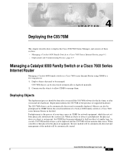
...for network equipment, which has not yet been physically slotted into the system rack. Deploying Objects The deployment process should be managed. Deployment informs the C65/76M of the presence of a Catalyst 6000 family switch or a Cisco 7600 series Internet Router in the physical equipment, the... new module will be automatically started. Objects can be discovered automatically or deployed manually. 2. Cisco 6500/7600 Series Manager User Guide 4-1 When a module is a two-step process: 1. When an object or device is predeployed, ...
...for network equipment, which has not yet been physically slotted into the system rack. Deploying Objects The deployment process should be managed. Deployment informs the C65/76M of the presence of a Catalyst 6000 family switch or a Cisco 7600 series Internet Router in the physical equipment, the... new module will be automatically started. Objects can be discovered automatically or deployed manually. 2. Cisco 6500/7600 Series Manager User Guide 4-1 When a module is a two-step process: 1. When an object or device is predeployed, ...