

Getting Started Guide
Page 4
... Network Connections Console emulator for initial boot-up Null modem serial cable (DB-9 -> RJ-45) to console connection Cisco WCS software, web user interface 10/100/1000BASE-T MDI cable Network Distribution system connection LAN link for management software connections WAN or LAN connection to Cisco 2500 Series Wireless Controllers are not currently supported. Note Direct...
... Network Connections Console emulator for initial boot-up Null modem serial cable (DB-9 -> RJ-45) to console connection Cisco WCS software, web user interface 10/100/1000BASE-T MDI cable Network Distribution system connection LAN link for management software connections WAN or LAN connection to Cisco 2500 Series Wireless Controllers are not currently supported. Note Direct...
Getting Started Guide
Page 7
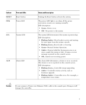
... • Off-No power to the system The system LED determines if the system is powered up. Caution Do not connect a Power over Ethernet (PoE) cable to halt. LED description: • Blinking Green-Controller image upgrading. • Amber-Controller status activity, such as firmware upgrade. • Blinking Amber-Controller error. The...
... • Off-No power to the system The system LED determines if the system is powered up. Caution Do not connect a Power over Ethernet (PoE) cable to halt. LED description: • Blinking Green-Controller image upgrading. • Amber-Controller status activity, such as firmware upgrade. • Blinking Amber-Controller error. The...

Getting Started Guide
Page 8
... Back Panel and Component Descriptions Ports and Slots POWER 48VDC State and Description The 48 V input power is not compatible with a 2504 controller. Cable Lock slot Note The Cisco 2106 power adapter is provided via an external AC/DC adapter. Power is enough power available to the controller. There is provided to...
... Back Panel and Component Descriptions Ports and Slots POWER 48VDC State and Description The 48 V input power is not compatible with a 2504 controller. Cable Lock slot Note The Cisco 2106 power adapter is provided via an external AC/DC adapter. Power is enough power available to the controller. There is provided to...

Getting Started Guide
Page 9
...; Cisco 2504 Wireless Controller software pre-loaded on the controller (software option configurable). • Optional licenses will need the following tools and information before you can install the controller: • Wireless controller hardware - Network, operating system service network, and access point cables as...; Two Number 6 Phillips pan-head screws for mounting the controller on CLI console (PC, laptop, or palmtop) - Null modem serial cable to the shipping container and save it for operation: Step 1 Step 2 Step 3 Open the shipping container and carefully remove the contents....
...; Cisco 2504 Wireless Controller software pre-loaded on the controller (software option configurable). • Optional licenses will need the following tools and information before you can install the controller: • Wireless controller hardware - Network, operating system service network, and access point cables as...; Two Number 6 Phillips pan-head screws for mounting the controller on CLI console (PC, laptop, or palmtop) - Null modem serial cable to the shipping container and save it for operation: Step 1 Step 2 Step 3 Open the shipping container and carefully remove the contents....

Getting Started Guide
Page 11
... equipment connected to the 10/100/1000 Mb/s Ethernet ports. • Make sure that the power cord can reach a 100 to the Cisco Wireless LAN Controller Configuration Guide for this installation. Enter help to see a list or refer to 240 VAC grounded electrical outlet. 3 Installing ... installation procedures: • Mounting the Controller, page 11 • Connecting the Controller Console Port, page 21 • Securing the Power Adapter Cable, page 21 • Installing a Security Lock, page 23 Mounting the Controller This section includes the following these guidelines: • Make sure ...
... equipment connected to the 10/100/1000 Mb/s Ethernet ports. • Make sure that the power cord can reach a 100 to the Cisco Wireless LAN Controller Configuration Guide for this installation. Enter help to see a list or refer to 240 VAC grounded electrical outlet. 3 Installing ... installation procedures: • Mounting the Controller, page 11 • Connecting the Controller Console Port, page 21 • Securing the Power Adapter Cable, page 21 • Installing a Security Lock, page 23 Mounting the Controller This section includes the following these guidelines: • Make sure ...

Getting Started Guide
Page 13
...shelf or desk, perform the following tasks to complete the installation: • Connecting the Controller Console Port • Securing the Power Adapter Cable • Connecting to the Network For configuration instructions about using rack-mount brackets, follow the correct procedures could result in a hazardous situation to...and overheating. Note Allow 3 inches of the 2504 controller as shown in Figure 5 with 19-inch rack mounting brackets and hardware from Cisco. Step 4 Step 5 After the controller is mounted on the table or shelf near an AC power source. Warning Read the wall-...
...shelf or desk, perform the following tasks to complete the installation: • Connecting the Controller Console Port • Securing the Power Adapter Cable • Connecting to the Network For configuration instructions about using rack-mount brackets, follow the correct procedures could result in a hazardous situation to...and overheating. Note Allow 3 inches of the 2504 controller as shown in Figure 5 with 19-inch rack mounting brackets and hardware from Cisco. Step 4 Step 5 After the controller is mounted on the table or shelf near an AC power source. Warning Read the wall-...

Getting Started Guide
Page 14
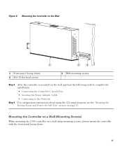
Figure 5 Installing the Rack-Mount Brackets to a firmly attached plywood mounting backboard. 14 For the best support of the controller and cables, make sure the controller is attached securely to wall studs or to the Sides of the Controller 1 282083 BASE MOUNT 1 1 #10-32 flat head screws (mounting screws for each side of the controller) Step 2 Mount the 2504 controller on the wall with the front panel facing down, as shown Figure 6.
Figure 5 Installing the Rack-Mount Brackets to a firmly attached plywood mounting backboard. 14 For the best support of the controller and cables, make sure the controller is attached securely to wall studs or to the Sides of the Controller 1 282083 BASE MOUNT 1 1 #10-32 flat head screws (mounting screws for each side of the controller) Step 2 Mount the 2504 controller on the wall with the front panel facing down, as shown Figure 6.
Getting Started Guide
Page 15
... Self Test" section on the wall, perform the following tasks to complete the installation: • Connecting the Controller Console Port • Securing the Power Adapter Cable • Connecting to the Network For configuration instructions about using mounting screws, always mount the controller with the front panel facing down. 15
... Self Test" section on the wall, perform the following tasks to complete the installation: • Connecting the Controller Console Port • Securing the Power Adapter Cable • Connecting to the Network For configuration instructions about using mounting screws, always mount the controller with the front panel facing down. 15

Getting Started Guide
Page 17
Figure 8 Place the Controller on the Mounting Screws 282085 2 1 2 1 Front panel (facing down . Note The front panel of the controller should be facing down ) 2 Mounting screws Step 5 After the controller is mounted ion the wall, perform the following tasks to complete the installation: • Connecting the Controller Console Port • Securing the Power Adapter Cable • Connecting to the Network 17 Step 4 Place the controller onto the mounting screws and slide it down until it lock into place, as shown in Figure 8.
Figure 8 Place the Controller on the Mounting Screws 282085 2 1 2 1 Front panel (facing down . Note The front panel of the controller should be facing down ) 2 Mounting screws Step 5 After the controller is mounted ion the wall, perform the following tasks to complete the installation: • Connecting the Controller Console Port • Securing the Power Adapter Cable • Connecting to the Network 17 Step 4 Place the controller onto the mounting screws and slide it down until it lock into place, as shown in Figure 8.

Getting Started Guide
Page 20
Figure 10 Mounting the Controller in a 19-Inch Rack 1 282086 1 #10-32 pan-head screws or #12-24 slotted head screws Step 3 Step 4 After the controller is mounted in the rack, perform the following tasks to complete the installation: • Connecting the Controller Console Port • Securing the Power Adapter Cable • Connecting to the Network For configuration instructions about using the CLI setup program, see the "Running the Bootup Script and Power-On Self Test" section on page 23. 20
Figure 10 Mounting the Controller in a 19-Inch Rack 1 282086 1 #10-32 pan-head screws or #12-24 slotted head screws Step 3 Step 4 After the controller is mounted in the rack, perform the following tasks to complete the installation: • Connecting the Controller Console Port • Securing the Power Adapter Cable • Connecting to the Network For configuration instructions about using the CLI setup program, see the "Running the Bootup Script and Power-On Self Test" section on page 23. 20
Getting Started Guide
Page 21
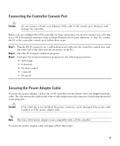
...that uses a VT-100 terminal emulator (such as HyperTerminal, ProComm, Minicom, or Tip). Note The Cisco 2106 power adapter is pulled or if the power adapter falls. To secure the power adapter cable and plug, follow these steps: 21 Caution If the relief clip is not installed, the power ... to the controller console port, follow these steps: Step 1 Step 2 Step 3 Plug the RJ-45 connector on a null-modem serial cable into the controller console port and the other end of the cable into the serial port of the PC. Connecting the Controller Console Port Caution Do not connect a...
...that uses a VT-100 terminal emulator (such as HyperTerminal, ProComm, Minicom, or Tip). Note The Cisco 2106 power adapter is pulled or if the power adapter falls. To secure the power adapter cable and plug, follow these steps: 21 Caution If the relief clip is not installed, the power ... to the controller console port, follow these steps: Step 1 Step 2 Step 3 Plug the RJ-45 connector on a null-modem serial cable into the controller console port and the other end of the cable into the serial port of the PC. Connecting the Controller Console Port Caution Do not connect a...

Getting Started Guide
Page 22
Figure 11 Plastic Relief Clip Step 2 Fasten the security clip with a screw to the existing hole on the back panel on the 2504 controller (see Figure 12). 281917 Step 1 Wrap the power adapter cable through the plastic security clip as shown in Figure 11. Figure 12 Securing the Power Adapter Cable 1 3 2 22 281918
Figure 11 Plastic Relief Clip Step 2 Fasten the security clip with a screw to the existing hole on the back panel on the 2504 controller (see Figure 12). 281917 Step 1 Wrap the power adapter cable through the plastic security clip as shown in Figure 11. Figure 12 Securing the Power Adapter Cable 1 3 2 22 281918

Getting Started Guide
Page 23
...configuration, loads its microcode into memory, verifies its operating system software load, and initializes itself with screw 1 2 AC/DC power adapter cable Power plugged into the power jack on the back of the controller. The Bootloader Options menu appears. You can install an optional customer-supplied... cable lock, such as described in the "Connecting the Controller Console Port" section on the back panel. Note When the controller receives ...
...configuration, loads its microcode into memory, verifies its operating system software load, and initializes itself with screw 1 2 AC/DC power adapter cable Power plugged into the power jack on the back of the controller. The Bootloader Options menu appears. You can install an optional customer-supplied... cable lock, such as described in the "Connecting the Controller Console Port" section on the back panel. Note When the controller receives ...

Getting Started Guide
Page 34
...-T Ethernet (RJ-45 physical port, UTP, Category-5 or higher cable). For example, to CISCO2504, enter config prompt "CISCO2504" and press Enter. You can set the automatic logout from 0 (never log out) to 160 minutes using double quotation marks. Figure 13 External Network Equipment Connection to the Controller 10/100/1000BASE-T MDI cable Cisco Access...
...-T Ethernet (RJ-45 physical port, UTP, Category-5 or higher cable). For example, to CISCO2504, enter config prompt "CISCO2504" and press Enter. You can set the automatic logout from 0 (never log out) to 160 minutes using double quotation marks. Figure 13 External Network Equipment Connection to the Controller 10/100/1000BASE-T MDI cable Cisco Access...

Getting Started Guide
Page 35
... your wireless network. 35 Refer to the Cisco Wireless LAN Controller Configuration Guide for basic operation. You have configured the controller, use Category-5, Category-5e, Category-6, or Category-7 Ethernet cables to connect up to 50 Cisco lightweight access points to the controller Ethernet ports... or to a hub or a switch, use an MDI-X or MDI cable (crossover or straight-through cable. When you have prepared the controller for ...
... your wireless network. 35 Refer to the Cisco Wireless LAN Controller Configuration Guide for basic operation. You have configured the controller, use Category-5, Category-5e, Category-6, or Category-7 Ethernet cables to connect up to 50 Cisco lightweight access points to the controller Ethernet ports... or to a hub or a switch, use an MDI-X or MDI cable (crossover or straight-through cable. When you have prepared the controller for ...

Getting Started Guide
Page 36
... controller using the Reset button, follow these steps: Step 1 Connect a PC to the Cisco Wireless Controller Configuration Guide for a description of the front panel LEDs. See Table 1 on cisco.com. The guide is available on page 5 for more information about configuring your 2504 controller...front panel of the unit. You can use the LED indications to a Controller Network Cisco 2504 Wireless Controller 10/100/1000BASE-T MDI cable Network 10/100/1000BASE-T MDI cables 282081 Cisco Access Points Checking the Controller LEDs If your controller. Figure 14 Access Points Connected ...
... controller using the Reset button, follow these steps: Step 1 Connect a PC to the Cisco Wireless Controller Configuration Guide for a description of the front panel LEDs. See Table 1 on cisco.com. The guide is available on page 5 for more information about configuring your 2504 controller...front panel of the unit. You can use the LED indications to a Controller Network Cisco 2504 Wireless Controller 10/100/1000BASE-T MDI cable Network 10/100/1000BASE-T MDI cables 282081 Cisco Access Points Checking the Controller LEDs If your controller. Figure 14 Access Points Connected ...
Getting Started Guide
Page 55
...), not regulated with the subject law by Cisco. Statement 157-VCCI Compliance for Class B Equipment Warning This is used near a radio or television receiver in a domestic environment, it may cause radio interference. If this is a Class B product based on the standard of UL-certified cables (that have the "UL" or "CSA" shown...
...), not regulated with the subject law by Cisco. Statement 157-VCCI Compliance for Class B Equipment Warning This is used near a radio or television receiver in a domestic environment, it may cause radio interference. If this is a Class B product based on the standard of UL-certified cables (that have the "UL" or "CSA" shown...