

Hardware Installation Guide
Page 2
...Access Registrar, Aironet, Catalyst, CCDA, CCDP, CCIE, CCIP, CCNA, CCNP, CCSP, Cisco, the Cisco Certified Internetwork Expert logo, Cisco IOS, Cisco Press, Cisco Systems, Cisco Systems Capital, the Cisco Systems logo, Cisco Unity, Enterprise/Solver, EtherChannel, EtherFast, EtherSwitch, Fast Step, Follow Me Browsing, FormShare, ...its peripheral devices. These limits are designed to provide reasonable protection against such interference in accordance with the instruction manual, may be required to correct any other of Cisco Systems, Inc.; This equipment has been tested and found to...
...Access Registrar, Aironet, Catalyst, CCDA, CCDP, CCIE, CCIP, CCNA, CCNP, CCSP, Cisco, the Cisco Certified Internetwork Expert logo, Cisco IOS, Cisco Press, Cisco Systems, Cisco Systems Capital, the Cisco Systems logo, Cisco Unity, Enterprise/Solver, EtherChannel, EtherFast, EtherSwitch, Fast Step, Follow Me Browsing, FormShare, ...its peripheral devices. These limits are designed to provide reasonable protection against such interference in accordance with the instruction manual, may be required to correct any other of Cisco Systems, Inc.; This equipment has been tested and found to...
Hardware Installation Guide
Page 35
... Cisco ... Maintenance Guidelines for Cisco Interface Cards The following safety warning statements apply to all individual Cisco interface card orders,... router chassis. Safety Warnings for Cisco Interface Cards The following maintenance guidelines apply to Cisco interface cards: • Keep the...to lift the chassis with all hardware procedures involving Cisco interface cards for Cisco access routers. Translations of the ESD-preventive wrist... by Cisco Systems, Inc. Statement 1040 OL-12842-01 3 Installing Cisco Interface Cards in Cisco Access Routers Recommended Practices for Cisco Interface ...
... Cisco ... Maintenance Guidelines for Cisco Interface Cards The following safety warning statements apply to all individual Cisco interface card orders,... router chassis. Safety Warnings for Cisco Interface Cards The following maintenance guidelines apply to Cisco interface cards: • Keep the...to lift the chassis with all hardware procedures involving Cisco interface cards for Cisco access routers. Translations of the ESD-preventive wrist... by Cisco Systems, Inc. Statement 1040 OL-12842-01 3 Installing Cisco Interface Cards in Cisco Access Routers Recommended Practices for Cisco Interface ...
Hardware Installation Guide
Page 64
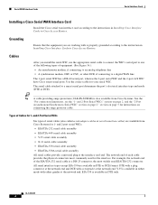
... end. For example, the network end of each cable provides the physical connectors most widely used for the interface. Tip A cable providing surge protection (CAB-SS-SURGE) is a DB-25 connector, the most commonly used EIA/TIA-232 connector. section on page 2." The network end of... interface card according to a smart serial port determines the port's electrical interface type and mode (DTE or DCE). Cables After you are available from Cisco Systems. See the "For connection limitations, see the "1- and 2-Port Serial WICs Six types of equipment. (See Figure 36.): • An ...
... end. For example, the network end of each cable provides the physical connectors most widely used for the interface. Tip A cable providing surge protection (CAB-SS-SURGE) is a DB-25 connector, the most commonly used EIA/TIA-232 connector. section on page 2." The network end of... interface card according to a smart serial port determines the port's electrical interface type and mode (DTE or DCE). Cables After you are available from Cisco Systems. See the "For connection limitations, see the "1- and 2-Port Serial WICs Six types of equipment. (See Figure 36.): • An ...
Hardware Installation Guide
Page 65
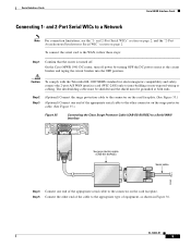
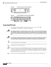
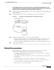
...the circuit breaker into the OFF position. OL-12843-01 5 To connect the serial card to the connector on the card faceplate. On the Cisco MWR 1941-DC router, turn off . Step 5 Connect the other connector on page 2. Serial Interface Cards Serial WAN Interface Cards Connecting 1- ... on the surge protector cable. (See Figure 35.) Figure 35 Connecting the Cisco Surge Protector Cable (CAB-SS-SURGE) to a Serial WAN Interface SERIAL 1 CONN SERIAL 0 WIC CONN 2T SEE MANUAL BEFORE INSTALLATION Surge protection cable (CAB-SS-SURGE) Serial cable 95969 Step 4 Connect one end of...
...the circuit breaker into the OFF position. OL-12843-01 5 To connect the serial card to the connector on the card faceplate. On the Cisco MWR 1941-DC router, turn off . Step 5 Connect the other connector on page 2. Serial Interface Cards Serial WAN Interface Cards Connecting 1- ... on the surge protector cable. (See Figure 35.) Figure 35 Connecting the Cisco Surge Protector Cable (CAB-SS-SURGE) to a Serial WAN Interface SERIAL 1 CONN SERIAL 0 WIC CONN 2T SEE MANUAL BEFORE INSTALLATION Surge protection cable (CAB-SS-SURGE) Serial cable 95969 Step 4 Connect one end of...
Hardware Installation Guide
Page 83
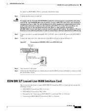
... BEFORE INSTALLATION BRI U Straight-through RJ-48C-to-RJ-48C cable to the RJ-48C port on , which indicates that the router is not sufficient protection in GR-1089-CORE, Issue 4) and require isolation from the exposed OSP cabling. The intra-building port(s) of the cable directly to the ISDN wall...
... BEFORE INSTALLATION BRI U Straight-through RJ-48C-to-RJ-48C cable to the RJ-48C port on , which indicates that the router is not sufficient protection in GR-1089-CORE, Issue 4) and require isolation from the exposed OSP cabling. The intra-building port(s) of the cable directly to the ISDN wall...
Hardware Installation Guide
Page 106
..., 4 = Ring 1 To connect a DSL interface card to the WAN, complete the following steps: Step 1 Confirm that connect to interfaces that the router is not sufficient protection in GR-1089-CORE, Issue 4) and require isolation from the exposed OSP cabling. These interfaces are designed for electromagnetic compatibility and safety, connect the HWIC...
..., 4 = Ring 1 To connect a DSL interface card to the WAN, complete the following steps: Step 1 Confirm that connect to interfaces that the router is not sufficient protection in GR-1089-CORE, Issue 4) and require isolation from the exposed OSP cabling. These interfaces are designed for electromagnetic compatibility and safety, connect the HWIC...
Hardware Installation Guide
Page 108
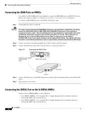
... to the S/T interface. Step 2 Connect one end of the equipment or subassembly must not be metallically connected to interfaces that the router is not sufficient protection in GR-1089-CORE, Issue 4) and require isolation from the exposed OSP cabling. Connecting the SHDSL Port on the G.SHDSL HWICs Connect... off. To connect an ISDN BRI S/T port to OSP wiring. The addition of the cable to establish connection between the HWIC and a network device. • Cisco HWIC-4SHDSL-Use a standard RJ-45 straight-through RJ-45-to-RJ-45 cable to the OSP or its wiring. Turn on HWICs Use an...
... to the S/T interface. Step 2 Connect one end of the equipment or subassembly must not be metallically connected to interfaces that the router is not sufficient protection in GR-1089-CORE, Issue 4) and require isolation from the exposed OSP cabling. Connecting the SHDSL Port on the G.SHDSL HWICs Connect... off. To connect an ISDN BRI S/T port to OSP wiring. The addition of the cable to establish connection between the HWIC and a network device. • Cisco HWIC-4SHDSL-Use a standard RJ-45 straight-through RJ-45-to-RJ-45 cable to the OSP or its wiring. Turn on HWICs Use an...
Hardware Installation Guide
Page 109
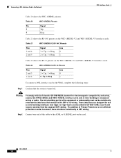
The intra-building port(s) of Primary Protectors is prevented, line -1 tip and line -3 ring will not work properly. If solid contact is not sufficient protection in subsequent connections. Figure 71 RJ-45 Pin Assignment 12345678 170068 Table 23 Pin 1 2 3 4 5 6 7 8 RJ-45 Signal Assignment by pin. DSL...Line 0 tip Line 0 ring Line 2 ring Line 3 tip Line 3 ring OL-12846-01 13 Caution Inserting an RJ-11 connector into the Cisco HWIC-4SHDSL port may deform pins 1 and 8, which may prevent solid contact between the connector and the plug in order to connect these interfaces ...
The intra-building port(s) of Primary Protectors is prevented, line -1 tip and line -3 ring will not work properly. If solid contact is not sufficient protection in subsequent connections. Figure 71 RJ-45 Pin Assignment 12345678 170068 Table 23 Pin 1 2 3 4 5 6 7 8 RJ-45 Signal Assignment by pin. DSL...Line 0 tip Line 0 ring Line 2 ring Line 3 tip Line 3 ring OL-12846-01 13 Caution Inserting an RJ-11 connector into the Cisco HWIC-4SHDSL port may deform pins 1 and 8, which may prevent solid contact between the connector and the plug in order to connect these interfaces ...

Hardware Installation Guide
Page 118
... risk of the following actions: • Order and install a NEBS Level 3/ETSI Compliance Kit. • Install an equivalent permanent protective earth connection, using a green and yellow 14 American Wire Gauge (AWG) grounding wire. If you find that a permanent earth connection...Cisco 2600 series, Cisco 3600 series, and Cisco 3700 series routers. LAN ports contain SELV circuits, and WAN ports contain TNV circuits. Some LAN and WAN ports both use RJ-45 connectors. Pinout and Cabling Specifications Voice Interface Cards Warning To avoid electric shock, do not have a permanent protective...
... risk of the following actions: • Order and install a NEBS Level 3/ETSI Compliance Kit. • Install an equivalent permanent protective earth connection, using a green and yellow 14 American Wire Gauge (AWG) grounding wire. If you find that a permanent earth connection...Cisco 2600 series, Cisco 3600 series, and Cisco 3700 series routers. LAN ports contain SELV circuits, and WAN ports contain TNV circuits. Some LAN and WAN ports both use RJ-45 connectors. Pinout and Cabling Specifications Voice Interface Cards Warning To avoid electric shock, do not have a permanent protective...
Hardware Installation Guide
Page 120
... the shield must be grounded at both ends. Note Ports on the card. (See Figure 82.) OL-12847-01 4 Caution To comply with integral circuit protection: FXS. Warning For connections outside the building where the equipment is installed, the following ports must be connected through an approved network termination unit with...
... the shield must be grounded at both ends. Note Ports on the card. (See Figure 82.) OL-12847-01 4 Caution To comply with integral circuit protection: FXS. Warning For connections outside the building where the equipment is installed, the following ports must be connected through an approved network termination unit with...
Hardware Installation Guide
Page 122
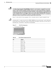
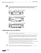
For proper operation, both jumpers on the VIC-2FXO card must be connected through an approved network termination unit with integral circuit protection. FXO Figure 83 2-Port FXO Card Front Panel (VIC-2FXO) IN USE 41217 IN USE VIC FXO 1 SEE MANUAL BEFORE INSTALLATION 0 Figure 84... 2-Port FXO Card Front Panel (VIC2-2FXO) VIC22FXO SEE MANUAL BEFORE INSTALLATION 1 0 IN USE 89038 Figure 85 4-Port FXO Card Front Panel (VIC2-4FXO) 89040 VIC24FXO 3 2 1 0 IN USE Setting Jumpers on loop-start, you may want to configure the FXO card for ground-start mode. In this setting...
For proper operation, both jumpers on the VIC-2FXO card must be connected through an approved network termination unit with integral circuit protection. FXO Figure 83 2-Port FXO Card Front Panel (VIC-2FXO) IN USE 41217 IN USE VIC FXO 1 SEE MANUAL BEFORE INSTALLATION 0 Figure 84... 2-Port FXO Card Front Panel (VIC2-2FXO) VIC22FXO SEE MANUAL BEFORE INSTALLATION 1 0 IN USE 89038 Figure 85 4-Port FXO Card Front Panel (VIC2-4FXO) 89040 VIC24FXO 3 2 1 0 IN USE Setting Jumpers on loop-start, you may want to configure the FXO card for ground-start mode. In this setting...
Hardware Installation Guide
Page 143
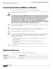
..., as described in GR-1089-CORE, Issue 4) and require isolation from the exposed OSP cabling. Related Documentation Related documentation is not sufficient protection in Figure 106. For more information, see the "Obtaining Documentation, Obtaining Support, and Security Guidelines" section on the analog modem WIC. ... to the pink RJ-11 port labeled LINE on page 6. • 1- and 2-Port V.90 Modem WICs for Cisco 2600 and Cisco 3600 Series Multiservice Platforms, Cisco IOS Release 12.2(8)T feature module • AT Command Set and Register Summary for V.90 WIC-1AM and WIC-2AM Analog...
..., as described in GR-1089-CORE, Issue 4) and require isolation from the exposed OSP cabling. Related Documentation Related documentation is not sufficient protection in Figure 106. For more information, see the "Obtaining Documentation, Obtaining Support, and Security Guidelines" section on the analog modem WIC. ... to the pink RJ-11 port labeled LINE on page 6. • 1- and 2-Port V.90 Modem WICs for Cisco 2600 and Cisco 3600 Series Multiservice Platforms, Cisco IOS Release 12.2(8)T feature module • AT Command Set and Register Summary for V.90 WIC-1AM and WIC-2AM Analog...

Hardware Installation Guide
Page 147
...(BPDU) guard • STP uplink fast • STP Root Guard • STP Unidirectional Link Detection (UDLD) • Port security • Protected Port • 802.1x port-based authentication • Storm control • Switched Port Analyzer (SPAN) • Internet Group Management Protocol (IGMP)...• Enable or disable per port based on unknown unicast or multicast flooding • Multicast groups • IP multicast support • Cisco Group Management Protocol (CGMP) client, CGMP fast-leave • Dynamic access ports • Dynamic trunk protocol • Dynamic VLANs OL-...
...(BPDU) guard • STP uplink fast • STP Root Guard • STP Unidirectional Link Detection (UDLD) • Port security • Protected Port • 802.1x port-based authentication • Storm control • Switched Port Analyzer (SPAN) • Internet Group Management Protocol (IGMP)...• Enable or disable per port based on unknown unicast or multicast flooding • Multicast groups • IP multicast support • Cisco Group Management Protocol (CGMP) client, CGMP fast-leave • Dynamic access ports • Dynamic trunk protocol • Dynamic VLANs OL-...
Hardware Installation Guide
Page 164
...and resources. Power up to 328 feet (100 meters). • For 100BASE-TX operation, Category 5 UTP cable is not sufficient protection in order to connect these interfaces metallically to OSP wiring. Warning To comply with the Telcordia GR-1089 NEBS standard for electromagnetic compatibility...The addition of Primary Protectors is required, for use as intra-building interfaces only (Type 2 or Type 4 ports as described in Cisco Access Routers.") Note Insert Fast Ethernet HWICs into WIC/VIC slots. These interfaces are designed for distances of the equipment or subassembly must...
...and resources. Power up to 328 feet (100 meters). • For 100BASE-TX operation, Category 5 UTP cable is not sufficient protection in order to connect these interfaces metallically to OSP wiring. Warning To comply with the Telcordia GR-1089 NEBS standard for electromagnetic compatibility...The addition of Primary Protectors is required, for use as intra-building interfaces only (Type 2 or Type 4 ports as described in Cisco Access Routers.") Note Insert Fast Ethernet HWICs into WIC/VIC slots. These interfaces are designed for distances of the equipment or subassembly must...