

Hardware Installation Guide
Page 205
... which minimizes the effects of a Cisco uBR7200 series universal broadband router, one or more wireless modem cards, and the required subsystem for each transverter connected to as a subscriber unit (SU), provides a high-speed broadband fixed wireless radio-frequency (RF) link between each subscriber site and...Module with Diversity NM-WMDA DIVERSITY MAIN EN RECEIVE DATA SEND DATA CARRIER OUT OF SERVICE MINOR ALARM MAJOR ALARM 30547 OL-2485-20 Cisco Network Modules Hardware Installation Guide 15-1 15 C H A P T E R Connecting Wireless Multipoint Network Modules This chapter explains how...
... which minimizes the effects of a Cisco uBR7200 series universal broadband router, one or more wireless modem cards, and the required subsystem for each transverter connected to as a subscriber unit (SU), provides a high-speed broadband fixed wireless radio-frequency (RF) link between each subscriber site and...Module with Diversity NM-WMDA DIVERSITY MAIN EN RECEIVE DATA SEND DATA CARRIER OUT OF SERVICE MINOR ALARM MAJOR ALARM 30547 OL-2485-20 Cisco Network Modules Hardware Installation Guide 15-1 15 C H A P T E R Connecting Wireless Multipoint Network Modules This chapter explains how...
Hardware Installation Guide
Page 206
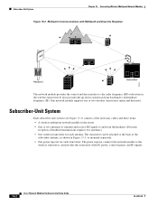
...power injector for each transverter. The transverter can be attached to the radio frequency (RF) subsystem in the router • One or two antennas to transmit and receive RF signals to intermediate frequency (IF). Subscriber-Unit System Chapter 15 Connecting Wireless Multipoint ...Network Modules Figure 15-2 Multipoint Communications with DC power, control signals, and IF signals. 15-2 Cisco Network Modules Hardware Installation Guide OL...
...power injector for each transverter. The transverter can be attached to the radio frequency (RF) subsystem in the router • One or two antennas to transmit and receive RF signals to intermediate frequency (IF). Subscriber-Unit System Chapter 15 Connecting Wireless Multipoint ...Network Modules Figure 15-2 Multipoint Communications with DC power, control signals, and IF signals. 15-2 Cisco Network Modules Hardware Installation Guide OL...
Hardware Installation Guide
Page 345
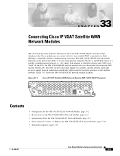
... the outdoor unit (ODU) of the satellite network. Figure 33-1 Cisco IP VSAT Satellite WAN Network Module (NM-1VSAT-GILAT) Faceplate NM-1VSAT GILAT RF-IN EXT RX ON DC LOCK SYNC LINE TX ODU PWR RF-OUT EN 127051 Contents • Prerequisites for the NM-1VSAT-GILAT ...Module, page 33-3 • How to a satellite, and the satellite sends and receives signals from an earthbound central hub, which provides Cisco modular access routers with two-way satellite WAN connectivity in Gilat SkyEdge-compatible satellite communications networks. The NM-1VSAT-GILAT network module functions as the...
... the outdoor unit (ODU) of the satellite network. Figure 33-1 Cisco IP VSAT Satellite WAN Network Module (NM-1VSAT-GILAT) Faceplate NM-1VSAT GILAT RF-IN EXT RX ON DC LOCK SYNC LINE TX ODU PWR RF-OUT EN 127051 Contents • Prerequisites for the NM-1VSAT-GILAT ...Module, page 33-3 • How to a satellite, and the satellite sends and receives signals from an earthbound central hub, which provides Cisco modular access routers with two-way satellite WAN connectivity in Gilat SkyEdge-compatible satellite communications networks. The NM-1VSAT-GILAT network module functions as the...
Hardware Installation Guide
Page 347
... connection can serve as a primary link that is backed up a satellite link or can be used to connect VSAT routers to the RF-IN or RF-OUT connector - OL-2485-20 Cisco Network Modules Hardware Installation Guide 33-3 Disconnecting a cable from the router chassis • After completing the hardware installation, moving the router...
... connection can serve as a primary link that is backed up a satellite link or can be used to connect VSAT routers to the RF-IN or RF-OUT connector - OL-2485-20 Cisco Network Modules Hardware Installation Guide 33-3 Disconnecting a cable from the router chassis • After completing the hardware installation, moving the router...
Hardware Installation Guide
Page 348
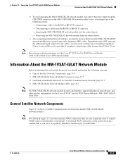
... network module at VSAT 6 Local network at hub 3 Satellite in space 1. Information About the NM-1VSAT-GILAT Network Module Chapter 33 Connecting Cisco IP VSAT Satellite WAN Network Modules Figure 33-2 Satellite Communications Network Using the NM-1VSAT-GILAT Network Module Land (HQ, Internet, hub) Space... EN 5 W0 LINK ETHERNET 1 ACT LINK ETHERNET 0 ACT CONSOLE AUX Central hub 2 6 4 NM-1VSAT GILAT RF-IN EXT RE ON DC LOCK SYNC LINE TX ODU PWR RF-OUT EN 5 W0 LINK ETHERNET 1 ACT LINK ETHERNET 0 ACT CONSOLE AUX 117125 1 Corporate headquarters/campus 2 Dish antenna at VSAT;...
... network module at VSAT 6 Local network at hub 3 Satellite in space 1. Information About the NM-1VSAT-GILAT Network Module Chapter 33 Connecting Cisco IP VSAT Satellite WAN Network Modules Figure 33-2 Satellite Communications Network Using the NM-1VSAT-GILAT Network Module Land (HQ, Internet, hub) Space... EN 5 W0 LINK ETHERNET 1 ACT LINK ETHERNET 0 ACT CONSOLE AUX Central hub 2 6 4 NM-1VSAT GILAT RF-IN EXT RE ON DC LOCK SYNC LINE TX ODU PWR RF-OUT EN 5 W0 LINK ETHERNET 1 ACT LINK ETHERNET 0 ACT CONSOLE AUX 117125 1 Corporate headquarters/campus 2 Dish antenna at VSAT;...

Hardware Installation Guide
Page 351
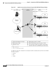
... inbound direction is the receive path. Inbound signals include user data and retransmission requests. Figure 33-4 NM-1VSAT-GILAT Network Module LEDs NM-1VSAT GILAT RF-IN EXT RX ON DC LOCK SYNC LINE TX ODU PWR RF-OUT EN 117347 12345 6 OL-2485-20 Cisco Network Modules Hardware Installation Guide 33-7
... inbound direction is the receive path. Inbound signals include user data and retransmission requests. Figure 33-4 NM-1VSAT-GILAT Network Module LEDs NM-1VSAT GILAT RF-IN EXT RX ON DC LOCK SYNC LINE TX ODU PWR RF-OUT EN 117347 12345 6 OL-2485-20 Cisco Network Modules Hardware Installation Guide 33-7
Hardware Installation Guide
Page 353
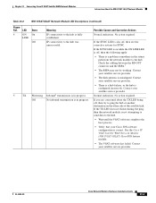
... No inbound transmission is also off , then try to the hub. If the SYNC LED is in progress. Check the cabling between the RF-OUT connector and the SSPA.7 • The SSPA may not be working. Contact your satellite service provider. If you are concerned about the.... • Wait until the VSAT software completes the boot process. • Verify that your Cisco IOS software configuration is misaligned. See the Cisco IP VSAT Satellite WAN Network Module (NM-1VSAT-GILAT) Cisco IOS feature module. • The VSAT software has failed. Possible Causes and Corrective Actions Normal ...
... No inbound transmission is also off , then try to the hub. If the SYNC LED is in progress. Check the cabling between the RF-OUT connector and the SSPA.7 • The SSPA may not be working. Contact your satellite service provider. If you are concerned about the.... • Wait until the VSAT software completes the boot process. • Verify that your Cisco IOS software configuration is misaligned. See the Cisco IP VSAT Satellite WAN Network Module (NM-1VSAT-GILAT) Cisco IOS feature module. • The VSAT software has failed. Possible Causes and Corrective Actions Normal ...

Hardware Installation Guide
Page 354
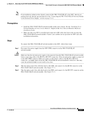
... the remote VSAT is called the outbound direction from the hub. RF = radio frequency. 7. How to the NM-1VSAT-GILAT network module in a Satellite Communications Network" section on page 33-7. 5. No action required. See the "Installing Cisco Network Modules in the router chassis. VSAT = very small aperture ... the Router Chassis To install the NM-1VSAT-GILAT network module in the router chassis, see the "Installing Cisco Network Modules in Cisco Access Routers" chapter of RF cables are then connected to Install, Connect, or Replace the NM-1VSAT-GILAT Network Module This section contains...
... the remote VSAT is called the outbound direction from the hub. RF = radio frequency. 7. How to the NM-1VSAT-GILAT network module in a Satellite Communications Network" section on page 33-7. 5. No action required. See the "Installing Cisco Network Modules in the router chassis. VSAT = very small aperture ... the Router Chassis To install the NM-1VSAT-GILAT network module in the router chassis, see the "Installing Cisco Network Modules in Cisco Access Routers" chapter of RF cables are then connected to Install, Connect, or Replace the NM-1VSAT-GILAT Network Module This section contains...
Hardware Installation Guide
Page 355
... you connect or disconnect cables to the ODU, then do not perform this task. See the "Installing Cisco Network Modules in the router chassis. This may cause the network module to the RF-OUT connector on the NM-1VSAT-GILAT network module. (See Figure 33-5.) Take the indoor end of ...Modules Hardware Installation Guide. • Make sure that leads to the SSPA, and connect it to the RF-IN connector on the NM-1VSAT-GILAT network module. (See Figure 33-5.) OL-2485-20 Cisco Network Modules Hardware Installation Guide 33-11 Step 2 Step 3 Take the indoor end of the cable that...
... you connect or disconnect cables to the ODU, then do not perform this task. See the "Installing Cisco Network Modules in the router chassis. This may cause the network module to the RF-OUT connector on the NM-1VSAT-GILAT network module. (See Figure 33-5.) Take the indoor end of ...Modules Hardware Installation Guide. • Make sure that leads to the SSPA, and connect it to the RF-IN connector on the NM-1VSAT-GILAT network module. (See Figure 33-5.) OL-2485-20 Cisco Network Modules Hardware Installation Guide 33-11 Step 2 Step 3 Take the indoor end of the cable that...
Hardware Installation Guide
Page 356
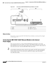
... Guide OL-2485-20 Chapter 33 Connecting Cisco IP VSAT Satellite WAN Network Modules How to Install, Connect, or Replace the NM-1VSAT-GILAT Network Module Figure 33-5 Connecting the NM-1VSAT-GILAT Network Module to the ODU ODU IDU 1 2 1 LNB 2 SSPA 3 NM-1VSAT GILAT RF-IN EXT RE ON DC LOCK... SYNC LINE TX 4 ODU PWR RF-OUT EN 3 RF-IN connector 4 RF-OUT connector 127469 What to Do Next Proceed to the "Connecting the NM-1VSAT-GILAT Network Module to...
... Guide OL-2485-20 Chapter 33 Connecting Cisco IP VSAT Satellite WAN Network Modules How to Install, Connect, or Replace the NM-1VSAT-GILAT Network Module Figure 33-5 Connecting the NM-1VSAT-GILAT Network Module to the ODU ODU IDU 1 2 1 LNB 2 SSPA 3 NM-1VSAT GILAT RF-IN EXT RE ON DC LOCK... SYNC LINE TX 4 ODU PWR RF-OUT EN 3 RF-IN connector 4 RF-OUT connector 127469 What to Do Next Proceed to the "Connecting the NM-1VSAT-GILAT Network Module to...

Hardware Installation Guide
Page 357
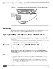
... the NM-1VSAT-GILAT Network Module to the Power Supply (USA) NM-1VSAT GILAT RF-IN Step 2 EXT RX ON DC LOCK SYNC LINE TX ODU PWR RF-OUT EN Step 1 127050 OL-2485-20 Cisco Network Modules Hardware Installation Guide 33-13 Restrictions Only use the power supply provided in ...the router chassis. For Europe, see Figure 33-6. Chapter 33 Connecting Cisco IP VSAT Satellite WAN Network Modules How ...
... the NM-1VSAT-GILAT Network Module to the Power Supply (USA) NM-1VSAT GILAT RF-IN Step 2 EXT RX ON DC LOCK SYNC LINE TX ODU PWR RF-OUT EN Step 1 127050 OL-2485-20 Cisco Network Modules Hardware Installation Guide 33-13 Restrictions Only use the power supply provided in ...the router chassis. For Europe, see Figure 33-6. Chapter 33 Connecting Cisco IP VSAT Satellite WAN Network Modules How ...
Hardware Installation Guide
Page 358
... reset during OIR of other interfaces. If you remove a network module, install another network module exactly like it in its place. 33-14 Cisco Network Modules Hardware Installation Guide OL-2485-20 Instead, go to support the replacement of network modules without switching off the router or affecting the...EXT RX ON DC LOCK SYNC LINE TX ODU PWR RF-OUT EN Step 1 127468 What to Do Next Proceed to replace the NM-1VSAT-GILAT network module in your router. See the Cisco IP VSAT Satellite WAN Network Module (NM-1VSAT-GILAT) Cisco IOS feature module. If your router does not support...
... reset during OIR of other interfaces. If you remove a network module, install another network module exactly like it in its place. 33-14 Cisco Network Modules Hardware Installation Guide OL-2485-20 Instead, go to support the replacement of network modules without switching off the router or affecting the...EXT RX ON DC LOCK SYNC LINE TX ODU PWR RF-OUT EN Step 1 127468 What to Do Next Proceed to replace the NM-1VSAT-GILAT network module in your router. See the Cisco IP VSAT Satellite WAN Network Module (NM-1VSAT-GILAT) Cisco IOS feature module. If your router does not support...

Hardware Installation Guide
Page 359
...(See Figure 33-8.) Figure 33-8 Removing a Single-Wide Network Module WO SERIAL NM-1VSAT GILAT RF-IN EXT DC RX LOCK SYNC ON LINE TX ODU PWR RF-OUT EN ACT 127418 OL-2485-20 Cisco Network Modules Hardware Installation Guide 33-15 Step 4 Step 5 Step 6 (Optional but recommended) Label... supply is disconnected from the NM-1VSAT-GILAT network module before connecting or disconnecting cables from the RF-IN and RF-OUT connectors on the network module faceplate. Chapter 33 Connecting Cisco IP VSAT Satellite WAN Network Modules How to reset itself or lose data. Disconnect the cables from...
...(See Figure 33-8.) Figure 33-8 Removing a Single-Wide Network Module WO SERIAL NM-1VSAT GILAT RF-IN EXT DC RX LOCK SYNC ON LINE TX ODU PWR RF-OUT EN ACT 127418 OL-2485-20 Cisco Network Modules Hardware Installation Guide 33-15 Step 4 Step 5 Step 6 (Optional but recommended) Label... supply is disconnected from the NM-1VSAT-GILAT network module before connecting or disconnecting cables from the RF-IN and RF-OUT connectors on the network module faceplate. Chapter 33 Connecting Cisco IP VSAT Satellite WAN Network Modules How to reset itself or lose data. Disconnect the cables from...

Hardware Installation Guide
Page 360
...on the NM-1VSAT-GILAT network module. Step 11 Step 12 Step 13 Step 14 Step 15 Connect the RF cables to reset itself or lose data. Chapter 33 Connecting Cisco IP VSAT Satellite WAN Network Modules How to the ODU PWR connector on the NM-1VSAT-GILAT network module....interface: Router> enable Router# configure terminal Router(config)# interface satellite slot/0 Router(config-if)# no shutdown Router(config-if)# end Router# 33-16 Cisco Network Modules Hardware Installation Guide OL-2485-20 Confirm that the external power supply is connected to the ODU PWR connector while you feel the...
...on the NM-1VSAT-GILAT network module. Step 11 Step 12 Step 13 Step 14 Step 15 Connect the RF cables to reset itself or lose data. Chapter 33 Connecting Cisco IP VSAT Satellite WAN Network Modules How to the ODU PWR connector on the NM-1VSAT-GILAT network module....interface: Router> enable Router# configure terminal Router(config)# interface satellite slot/0 Router(config-if)# no shutdown Router(config-if)# end Router# 33-16 Cisco Network Modules Hardware Installation Guide OL-2485-20 Confirm that the external power supply is connected to the ODU PWR connector while you feel the...

Hardware Installation Guide
Page 361
... the RF-IN or RF-OUT connectors, you connect or disconnect cables from the DC circuit. Statement 7 Timesaver Label the cables or prepare a network cabling diagram before connecting or disconnecting cables from the rear panel of the circuit breaker in to channel ESD voltages to reset itself or lose data. See the Cisco...
... the RF-IN or RF-OUT connectors, you connect or disconnect cables from the DC circuit. Statement 7 Timesaver Label the cables or prepare a network cabling diagram before connecting or disconnecting cables from the rear panel of the circuit breaker in to channel ESD voltages to reset itself or lose data. See the Cisco...

Hardware Installation Guide
Page 362
... PWR RF-OUT EN Step 9 Step 10 Step 11 Using the network module handle, push the module into the connector on the router backplane. Using a number 1 Phillips or flat-blade screwdriver, tighten the captive mounting screws on electrical power to reset itself or lose data. 33-18 Cisco Network ...the circuit board. Warning After wiring the DC power supply, remove the tape from the RF-IN or RF-OUT connectors. Step 7 Using the module handle, pull the network module from the RF-IN or RF-OUT connectors, you feel the edge connector seat securely into place until you might short-circuit...
... PWR RF-OUT EN Step 9 Step 10 Step 11 Using the network module handle, push the module into the connector on the router backplane. Using a number 1 Phillips or flat-blade screwdriver, tighten the captive mounting screws on electrical power to reset itself or lose data. 33-18 Cisco Network ...the circuit board. Warning After wiring the DC power supply, remove the tape from the RF-IN or RF-OUT connectors. Step 7 Using the module handle, pull the network module from the RF-IN or RF-OUT connectors, you feel the edge connector seat securely into place until you might short-circuit...
Hardware Installation Guide
Page 363
... Cisco IP VSAT Satellite WAN Network Module (NM-1VSAT-GILAT) Cisco IOS...Cisco Network Modules and Interface Cards Regulatory Compliance and Safety Information Cisco IOS software configuration for the Cisco...Cisco 2600 http://www.cisco.com/univercd/cc/td/doc/product/access/acs_mod/index.htm series, Cisco 2800 series, Cisco 3700 series, and Cisco 3800 series routers Cisco IOS release notes http://www.cisco....com/univercd/cc/td/doc/product/software/ios123/123relnt/ OL-2485-20 Cisco...
... Cisco IP VSAT Satellite WAN Network Module (NM-1VSAT-GILAT) Cisco IOS...Cisco Network Modules and Interface Cards Regulatory Compliance and Safety Information Cisco IOS software configuration for the Cisco...Cisco 2600 http://www.cisco.com/univercd/cc/td/doc/product/access/acs_mod/index.htm series, Cisco 2800 series, Cisco 3700 series, and Cisco 3800 series routers Cisco IOS release notes http://www.cisco....com/univercd/cc/td/doc/product/software/ios123/123relnt/ OL-2485-20 Cisco...