
Hardware Installation Guide
Page 23
... Cisco 837 router. Figure 1-3 Cisco 837 Back Panel ETHERNET CONSOLE Cisco 837 4 3 2 1 ADSL 1 3 5 2 4 6 +18 VDC 7 8 1 Ethernet port 4 connects to 5 Console port connects to PC or Ethernet network device terminal 2 Ethernet port 3 connects to 6 ADSL port connects to external Ethernet network device wall jack 3 Ethernet port 2 connects to 7 Input jack connects to desktop Ethernet network device power supply 4 Ethernet port 1 connects to 8 Power...
... Cisco 837 router. Figure 1-3 Cisco 837 Back Panel ETHERNET CONSOLE Cisco 837 4 3 2 1 ADSL 1 3 5 2 4 6 +18 VDC 7 8 1 Ethernet port 4 connects to 5 Console port connects to PC or Ethernet network device terminal 2 Ethernet port 3 connects to 6 ADSL port connects to external Ethernet network device wall jack 3 Ethernet port 2 connects to 7 Input jack connects to desktop Ethernet network device power supply 4 Ethernet port 1 connects to 8 Power...

Hardware Installation Guide
Page 24
... Multiplexer (DSLAM) successfully. Green Blinks when the LAN port transmits data to the Ethernet interface successfully. Green Blinks when the ADSL receives data. Blinks when Ethernet 3 receives or sends data, or when data passes through Ethernet 4. Blinks when Ethernet 4 receives... E4 Status LAN_RxD LAN_TxD Color Function Green On when DC power is being supplied to the router. Off when no data is being uploaded. Cisco 837 Router and SOHO 97 Router Hardware Installation Guide 1-6 78-14781-02 Router Overview Chapter 1 Product Overview LED Functions Table 1-2 summarizes ...
... Multiplexer (DSLAM) successfully. Green Blinks when the LAN port transmits data to the Ethernet interface successfully. Green Blinks when the ADSL receives data. Blinks when Ethernet 3 receives or sends data, or when data passes through Ethernet 4. Blinks when Ethernet 4 receives... E4 Status LAN_RxD LAN_TxD Color Function Green On when DC power is being supplied to the router. Off when no data is being uploaded. Cisco 837 Router and SOHO 97 Router Hardware Installation Guide 1-6 78-14781-02 Router Overview Chapter 1 Product Overview LED Functions Table 1-2 summarizes ...

Hardware Installation Guide
Page 29
...you plan to configure the software using a terminal or a PC connected to the router: hub, server, workstation, or PC. All these devices. Table 2-1 Router Box Contents • Power cord (black) • Desktop power supply • ADSL cable (lavender) • Console cable, RJ-45-to-DB-9 (light blue... service representative. Remove the desktop power supply and the black power cord from the Open Me First bag. Gather the Ethernet devices to be connected to the router, provide the terminal or PC. 78-14781-02 Cisco 837 Router and SOHO 97 Router Hardware Installation Guide 2-5
...you plan to configure the software using a terminal or a PC connected to the router: hub, server, workstation, or PC. All these devices. Table 2-1 Router Box Contents • Power cord (black) • Desktop power supply • ADSL cable (lavender) • Console cable, RJ-45-to-DB-9 (light blue... service representative. Remove the desktop power supply and the black power cord from the Open Me First bag. Gather the Ethernet devices to be connected to the router, provide the terminal or PC. 78-14781-02 Cisco 837 Router and SOHO 97 Router Hardware Installation Guide 2-5

Hardware Installation Guide
Page 32
...network cable connections could cause it to disconnect from the wall. Cisco 837 Router and SOHO 97 Router Hardware Installation Guide 2-8 78-14781-02 with 8-mm drill bit) to reduce strain on the cable connections. • The power supply must be easily visible. • The back panel must face...to secure the screws. The following requirements must rest on the power supply cable could pull the router from the connector on the router back panel. If the screws are used as the floor or a table. If the power supply is not supported, strain on a horizontal surface, such as...
...network cable connections could cause it to disconnect from the wall. Cisco 837 Router and SOHO 97 Router Hardware Installation Guide 2-8 78-14781-02 with 8-mm drill bit) to reduce strain on the cable connections. • The power supply must be easily visible. • The back panel must face...to secure the screws. The following requirements must rest on the power supply cable could pull the router from the connector on the router back panel. If the screws are used as the floor or a table. If the power supply is not supported, strain on a horizontal surface, such as...

Hardware Installation Guide
Page 34
Connect the ADSL line. 3. Connect a terminal or PC to the router. 2. Hang the router on a horizontal surface. Connect the Ethernet devices to the router for software configuration using the router LEDs. 2-10 Cisco 837 Router and SOHO 97 Router Hardware Installation Guide 78-14781-02 Place the power supply on the screws as shown in Figure 2-3. Connect the router to perform the following...
Connect the ADSL line. 3. Connect a terminal or PC to the router. 2. Hang the router on a horizontal surface. Connect the Ethernet devices to the router for software configuration using the router LEDs. 2-10 Cisco 837 Router and SOHO 97 Router Hardware Installation Guide 78-14781-02 Place the power supply on the screws as shown in Figure 2-3. Connect the router to perform the following...
Hardware Installation Guide
Page 40
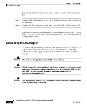
... Guide 78-14781-02 The connection procedure applies to both the Cisco 837 router and the SOHO 97 router.) Warning The device is intended to the SOHO 97 router. Connecting the AC Adapter To connect the power supply, follow the steps given after Figure 2-6. (Figure 2-6 depicts a Cisco 837 router, but it also applies to be grounded. Warning This equipment is...
... Guide 78-14781-02 The connection procedure applies to both the Cisco 837 router and the SOHO 97 router.) Warning The device is intended to the SOHO 97 router. Connecting the AC Adapter To connect the power supply, follow the steps given after Figure 2-6. (Figure 2-6 depicts a Cisco 837 router, but it also applies to be grounded. Warning This equipment is...

Hardware Installation Guide
Page 41
Chapter 2 Installation Figure 2-6 Connecting the AC Adapter Installing the Router 1 ETHERNET CONSOLE Cisco 837 4 3 ADSL 2 1 +18 VDC ON OFF 2 5 3 4 1 Cisco 837 router 2 Router input jack 3 Power cord 4 Desktop power supply 5 Power cord plug Perform the following steps to connect the router to the AC adapter: Step 1 Step 2 Step 3 Connect one end the power supply cable to your router, that power supply may not provide all the features that are...
Chapter 2 Installation Figure 2-6 Connecting the AC Adapter Installing the Router 1 ETHERNET CONSOLE Cisco 837 4 3 ADSL 2 1 +18 VDC ON OFF 2 5 3 4 1 Cisco 837 router 2 Router input jack 3 Power cord 4 Desktop power supply 5 Power cord plug Perform the following steps to connect the router to the AC adapter: Step 1 Step 2 Step 3 Connect one end the power supply cable to your router, that power supply may not provide all the features that are...

Hardware Installation Guide
Page 50
... that the cable is set to ON. 2. Make sure that the power switch is not physically damaged. Cisco 837 Router and SOHO 97 Router Hardware Installation Guide 3-2 78-14781-02 No connection to ADSL link. (The CD LED on the router. If the problem continues, the power supply might be faulty. Make sure that the connectors at both ends...
... that the cable is set to ON. 2. Make sure that the power switch is not physically damaged. Cisco 837 Router and SOHO 97 Router Hardware Installation Guide 3-2 78-14781-02 No connection to ADSL link. (The CD LED on the router. If the problem continues, the power supply might be faulty. Make sure that the connectors at both ends...
Hardware Installation Guide
Page 53
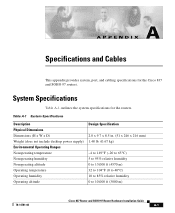
Table A-1 System Specifications Description Physical Dimensions Dimensions (H x W x D) Weight (does not include desktop power supply) Environmental Operating Ranges Nonoperating temperature Nonoperating humidity Nonoperating altitude Operating temperature Operating humidity Operating altitude Design Specification 2.0 x 9.7 x 8.5...to 40°C) 10 to 85% relative humidity 0 to 10,000 ft (3000 m) 78-14781-02 Cisco 837 Router and SOHO 97 Router Hardware Installation Guide A-1 A A P P E N D I X Specifications and Cables This appendix provides system, port, and cabling specifications for the...
Table A-1 System Specifications Description Physical Dimensions Dimensions (H x W x D) Weight (does not include desktop power supply) Environmental Operating Ranges Nonoperating temperature Nonoperating humidity Nonoperating altitude Operating temperature Operating humidity Operating altitude Design Specification 2.0 x 9.7 x 8.5...to 40°C) 10 to 85% relative humidity 0 to 10,000 ft (3000 m) 78-14781-02 Cisco 837 Router and SOHO 97 Router Hardware Installation Guide A-1 A A P P E N D I X Specifications and Cables This appendix provides system, port, and cabling specifications for the...

Hardware Installation Guide
Page 57
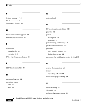
..., connecting 2-16 accessory kit 2-5 adapter, included 2-5 ADSL line, connecting (figure) 2-13 port 1-2 altitude specifications (table) A-1 autosensing 1-1 B back panel (figure) 1-5 C cables included with router 2-5 cables and router damage 2-6 cabling distance, maximum (table) A-4 caution, defined x Cisco Router Web Setup 2-21 connecting AC adapter 2-16 console port to async modem 2-18 power supply 2-16 terminal or PC to console port...
..., connecting 2-16 accessory kit 2-5 adapter, included 2-5 ADSL line, connecting (figure) 2-13 port 1-2 altitude specifications (table) A-1 autosensing 1-1 B back panel (figure) 1-5 C cables included with router 2-5 cables and router damage 2-6 cabling distance, maximum (table) A-4 caution, defined x Cisco Router Web Setup 2-21 connecting AC adapter 2-16 console port to async modem 2-18 power supply 2-16 terminal or PC to console port...
Hardware Installation Guide
Page 58
... for 2-1 verifying 2-20 IPSec Hardware Accelerator 1-3 N note, defined x P PC configuration, checking 2-20 pinouts A-2 power description A-2 problems 3-2 power supply, connecting 2-16 preinstallation activities 2-5 problems after router is running 3-3 during first startup 3-2 procedure for installing the router 2-10 to 2-5 router damage, preventing 2-6 S safety warnings 2-2 SDRAM 1-2 software-based encryption 1-1 IN-6 Cisco 837 Router and SOHO 97 Router Hardware Installation Guide 78-14781-02
... for 2-1 verifying 2-20 IPSec Hardware Accelerator 1-3 N note, defined x P PC configuration, checking 2-20 pinouts A-2 power description A-2 problems 3-2 power supply, connecting 2-16 preinstallation activities 2-5 problems after router is running 3-3 during first startup 3-2 procedure for installing the router 2-10 to 2-5 router damage, preventing 2-6 S safety warnings 2-2 SDRAM 1-2 software-based encryption 1-1 IN-6 Cisco 837 Router and SOHO 97 Router Hardware Installation Guide 78-14781-02


