
Installation Guide
Page 5
...Document Conventions xxi Obtaining Documentation xxiv Cisco.com xxiv Ordering Documentation xxv Documentation Feedback xxv Obtaining Technical Assistance xxv Cisco Technical Support Website xxvi Submitting a ...Service Request xxvi Definitions of Service Request Severity xxvii Obtaining Additional Publications and Information xxvii Product Overview 1-1 Physical and Functional Overviews 1-2 Gigabit Route Processor 1-4 GRP Memory Components 1-7 System Status LEDs 1-10 Soft Reset Switch 1-11 PCMCIA Slots 1-12 Asynchronous Serial Ports 1-12 Ethernet...
...Document Conventions xxi Obtaining Documentation xxiv Cisco.com xxiv Ordering Documentation xxv Documentation Feedback xxv Obtaining Technical Assistance xxv Cisco Technical Support Website xxvi Submitting a ...Service Request xxvi Definitions of Service Request Severity xxvii Obtaining Additional Publications and Information xxvii Product Overview 1-1 Physical and Functional Overviews 1-2 Gigabit Route Processor 1-4 GRP Memory Components 1-7 System Status LEDs 1-10 Soft Reset Switch 1-11 PCMCIA Slots 1-12 Asynchronous Serial Ports 1-12 Ethernet...
Installation Guide
Page 6
Chapter 2 Ethernet Ports 1-22 Line Cards 1-22 Alarm Card 1-23 Switch Fabric 1-25 Power Supplies 1-28 AC-Input Power Supply 1-29 DC-Input power Supply 1-30 Power ... Power Guidelines 2-11 AC-Powered Systems 2-12 DC-Powered Systems 2-14 System Grounding Connection Guidelines 2-15 Site Wiring Guidelines 2-15 SONET Connection Guidelines 2-16 Power Budget 2-17 Approximating the Line Card Power Margin 2-18 Multimode Power Budget Example with Sufficient Power for Transmission 2-20 vi Cisco 12012 Gigabit Switch Router Installation and Configuration Guide
Chapter 2 Ethernet Ports 1-22 Line Cards 1-22 Alarm Card 1-23 Switch Fabric 1-25 Power Supplies 1-28 AC-Input Power Supply 1-29 DC-Input power Supply 1-30 Power ... Power Guidelines 2-11 AC-Powered Systems 2-12 DC-Powered Systems 2-14 System Grounding Connection Guidelines 2-15 Site Wiring Guidelines 2-15 SONET Connection Guidelines 2-16 Power Budget 2-17 Approximating the Line Card Power Margin 2-18 Multimode Power Budget Example with Sufficient Power for Transmission 2-20 vi Cisco 12012 Gigabit Switch Router Installation and Configuration Guide
Installation Guide
Page 7
...Limit 2-20 Single-Mode Transmission 2-21 SONET Single-Mode Power Budget Example 2-21 Using Statistics to Estimate the Power Budget 2-22 Tools for Installation 2-22 Unpacking the Cisco 12012 2-23 Checking the Shipping Packaging Contents 2-23 Site Log 2-24 Installing a Cisco 12012 3-1 Installing the Brace Bar 3-3 Removing the Cisco 12012 Components before Installing the Frame 3-4 ...Connecting Route Processor Cables 3-33 GRP Console and Auxiliary Port Connection Equipment 3-33 GRP Console Port Signals 3-35 GRP Auxiliary Port Signals 3-35 GRP Ethernet Connection Equipment 3-36 Table of Contents vii
...Limit 2-20 Single-Mode Transmission 2-21 SONET Single-Mode Power Budget Example 2-21 Using Statistics to Estimate the Power Budget 2-22 Tools for Installation 2-22 Unpacking the Cisco 12012 2-23 Checking the Shipping Packaging Contents 2-23 Site Log 2-24 Installing a Cisco 12012 3-1 Installing the Brace Bar 3-3 Removing the Cisco 12012 Components before Installing the Frame 3-4 ...Connecting Route Processor Cables 3-33 GRP Console and Auxiliary Port Connection Equipment 3-33 GRP Console Port Signals 3-35 GRP Auxiliary Port Signals 3-35 GRP Ethernet Connection Equipment 3-36 Table of Contents vii

Installation Guide
Page 8
... Guidelines 3-40 PRP Console Port Signals 3-42 PRP Auxiliary Port Signals 3-42 PRP Ethernet Connection Equipment 3-43 PRP Ethernet Connections 3-44 Connecting Alarm Card Cables 3-48 Connecting System Grounding 3-50 Connecting Power...for System Startup 4-2 Starting the System and Observing Initial Conditions 4-3 Manually Booting the System 4-7 Configuring the Cisco 12012 4-8 Performing a Basic Manual Configuration Using the Setup Facility or the setup Command 4-8 Configuring the Global Parameters ...Memory Card in a RP 4-34 viii Cisco 12012 Gigabit Switch Router Installation and Configuration Guide
... Guidelines 3-40 PRP Console Port Signals 3-42 PRP Auxiliary Port Signals 3-42 PRP Ethernet Connection Equipment 3-43 PRP Ethernet Connections 3-44 Connecting Alarm Card Cables 3-48 Connecting System Grounding 3-50 Connecting Power...for System Startup 4-2 Starting the System and Observing Initial Conditions 4-3 Manually Booting the System 4-7 Configuring the Cisco 12012 4-8 Performing a Basic Manual Configuration Using the Setup Facility or the setup Command 4-8 Configuring the Global Parameters ...Memory Card in a RP 4-34 viii Cisco 12012 Gigabit Switch Router Installation and Configuration Guide

Installation Guide
Page 14
...Console and Auxiliary Port Connections 3-33 RJ-45 and MII Ethernet Connections 3-37 Ethernet MII Receptacle 3-38 Ethernet RJ-45 Receptacle 3-39 PRP Console and Auxiliary Port Connections 3-41 Using the Ethernet Port on the PRP 3-44 RJ-45 Receptacle and ...Plug (Horizontal Orientation) 3-45 Straight-Through Cable Pinout (Connecting MDI Ethernet Port to MDI-X Wiring) 3-46 Crossover Cable Pinout (for Connecting Two PRPs) 3-46 Alarm Card...3-63 RP Alphanumeric LED Displays (Partial Front Panel View) 4-3 xiv Cisco 12012 Gigabit Switch Router Installation and Configuration Guide
...Console and Auxiliary Port Connections 3-33 RJ-45 and MII Ethernet Connections 3-37 Ethernet MII Receptacle 3-38 Ethernet RJ-45 Receptacle 3-39 PRP Console and Auxiliary Port Connections 3-41 Using the Ethernet Port on the PRP 3-44 RJ-45 Receptacle and ...Plug (Horizontal Orientation) 3-45 Straight-Through Cable Pinout (Connecting MDI Ethernet Port to MDI-X Wiring) 3-46 Crossover Cable Pinout (for Connecting Two PRPs) 3-46 Alarm Card...3-63 RP Alphanumeric LED Displays (Partial Front Panel View) 4-3 xiv Cisco 12012 Gigabit Switch Router Installation and Configuration Guide
Installation Guide
Page 18
Table 3-7 Table 3-8 Table 3-9 Table 3-10 Table 4-1 Table 4-2 Table 4-3 Table 4-4 Table 4-5 Table 4-6 Table 4-7 Table 5-1 Table 5-2 PRP RJ-45 Ethernet Receptacle Pinout 3-45 Specifications and Connection Limits for 100-Mbps Transmission 3-47 IEEE 802.3u Physical Characteristics 3-47 Alarm 1 and Alarm 2 Connector Pinout 3-49 RP ... Broadcast Address Destination 4-30 System Console Terminal Transmission Rate Settings 4-30 RP Alphanumeric LED Display Messages 5-10 Line Card Alphanumeric LED Display Messages 5-13 xviii Cisco 12012 Gigabit Switch Router Installation and Configuration Guide
Table 3-7 Table 3-8 Table 3-9 Table 3-10 Table 4-1 Table 4-2 Table 4-3 Table 4-4 Table 4-5 Table 4-6 Table 4-7 Table 5-1 Table 5-2 PRP RJ-45 Ethernet Receptacle Pinout 3-45 Specifications and Connection Limits for 100-Mbps Transmission 3-47 IEEE 802.3u Physical Characteristics 3-47 Alarm 1 and Alarm 2 Connector Pinout 3-49 RP ... Broadcast Address Destination 4-30 System Console Terminal Transmission Rate Settings 4-30 RP Alphanumeric LED Display Messages 5-10 Line Card Alphanumeric LED Display Messages 5-13 xviii Cisco 12012 Gigabit Switch Router Installation and Configuration Guide
Installation Guide
Page 33
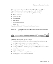
... The primary functions of the GRP are as follows: • Downloading the Cisco IOS software to all of the installed line cards at power up • Providing a console (terminal) port for router configuration • Providing an auxiliary port for other external equipment (such as...8226; PCMCIA slots • Asynchronous serial ports • Ethernet port If you have a PRP, see Figure 1-2) and its use as modems) • Providing an IEEE 802.3, 10/100-megabits-per-second (Mbps) Ethernet port for the Cisco 12012. Physical and Functional Overviews This section provides information about the ...
... The primary functions of the GRP are as follows: • Downloading the Cisco IOS software to all of the installed line cards at power up • Providing a console (terminal) port for router configuration • Providing an auxiliary port for other external equipment (such as...8226; PCMCIA slots • Asynchronous serial ports • Ethernet port If you have a PRP, see Figure 1-2) and its use as modems) • Providing an IEEE 802.3, 10/100-megabits-per-second (Mbps) Ethernet port for the Cisco 12012. Physical and Functional Overviews This section provides information about the ...
Installation Guide
Page 36
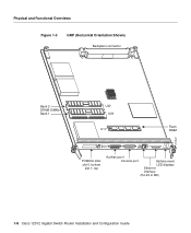
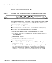
Physical and Functional Overviews Figure 1-3 GRP (Horizontal Orientation Shown) Backplane connector H10547 Bank 2 DRAM DIMMs Bank 1 U42 U39 U17 Flash SIMM EJECT SSLOLOT-T0-1 RESET AUX COLL RX LINK TX RJ-45 MII GIGABIT ROUTE PROCESSOR PCMCIA slots slot 0: bottom slot 1: top Auxiliary port Console port Alphanumeric LED displays Ethernet interface (RJ-45 or MII) 1-8 Cisco 12012 Gigabit Switch Router Installation and Configuration Guide
Physical and Functional Overviews Figure 1-3 GRP (Horizontal Orientation Shown) Backplane connector H10547 Bank 2 DRAM DIMMs Bank 1 U42 U39 U17 Flash SIMM EJECT SSLOLOT-T0-1 RESET AUX COLL RX LINK TX RJ-45 MII GIGABIT ROUTE PROCESSOR PCMCIA slots slot 0: bottom slot 1: top Auxiliary port Console port Alphanumeric LED displays Ethernet interface (RJ-45 or MII) 1-8 Cisco 12012 Gigabit Switch Router Installation and Configuration Guide
Installation Guide
Page 38
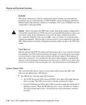
... software and microcode images. The LEDs indicate link activity, collision detection, data transmission, and data reception. 1-10 Cisco 12012 Gigabit Switch Router Installation and Configuration Guide Four RJ-45 Ethernet port LEDs: these LEDs light when the slot is not user configurable or field-upgradeable. Caution Before you replace the GRP in the system...
... software and microcode images. The LEDs indicate link activity, collision detection, data transmission, and data reception. 1-10 Cisco 12012 Gigabit Switch Router Installation and Configuration Guide Four RJ-45 Ethernet port LEDs: these LEDs light when the slot is not user configurable or field-upgradeable. Caution Before you replace the GRP in the system...
Installation Guide
Page 39
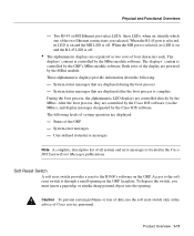
... and the RJ-45 LED is located in the GRP faceplate. The following : - Physical and Functional Overviews - Two RJ-45 or MII Ethernet port select LEDs: these LEDs, when on and the MII LED is on , identify which one of four characters each. When the MII port... displays provide information about the following levels of system operation are organized as two rows of the two Ethernet connections you must insert a paperclip or similar sharp pointed object into the opening in the Cisco IOS System Error Messages publications. After the boot process, they are powered by the...
... and the RJ-45 LED is located in the GRP faceplate. The following : - Physical and Functional Overviews - Two RJ-45 or MII Ethernet port select LEDs: these LEDs, when on and the MII LED is on , identify which one of four characters each. When the MII port... displays provide information about the following levels of system operation are organized as two rows of the two Ethernet connections you must insert a paperclip or similar sharp pointed object into the opening in the Cisco IOS System Error Messages publications. After the boot process, they are powered by the...
Installation Guide
Page 40
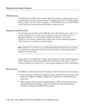
...memory card or an input/output (I/O) device as long as a standard by the IEEE 802.3u standard. 1-12 Cisco 12012 Gigabit Switch Router Installation and Configuration Guide Each PCMCIA slot has an ejector button for Telnet management. the auxiliary port supports flow control ... auxiliary port is an Electronics Industries Association/Telecommunications Industry Association (EIA/TIA)-232 receptacle (female) that provides additional flexibility in Ethernet connections. Asynchronous Serial Ports Two asynchronous serial ports on the GRP, the console and auxiliary ports, allow you to connect ...
...memory card or an input/output (I/O) device as long as a standard by the IEEE 802.3u standard. 1-12 Cisco 12012 Gigabit Switch Router Installation and Configuration Guide Each PCMCIA slot has an ejector button for Telnet management. the auxiliary port supports flow control ... auxiliary port is an Electronics Industries Association/Telecommunications Industry Association (EIA/TIA)-232 receptacle (female) that provides additional flexibility in Ethernet connections. Asynchronous Serial Ports Two asynchronous serial ports on the GRP, the console and auxiliary ports, allow you to connect ...
Installation Guide
Page 41
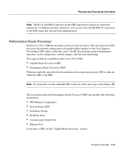
... protocols and distributes updates to indicate either the MDI RJ-45 connection or the MII connection, but not both simultaneously. Performance Route Processor Each Cisco 12012 GSR has one Ethernet interface; Product Overview 1-13 Physical and Functional Overviews Note The RJ-45 and MII receptacles on the GRP represent two physical connection options...
... protocols and distributes updates to indicate either the MDI RJ-45 connection or the MII connection, but not both simultaneously. Performance Route Processor Each Cisco 12012 GSR has one Ethernet interface; Product Overview 1-13 Physical and Functional Overviews Note The RJ-45 and MII receptacles on the GRP represent two physical connection options...
Installation Guide
Page 42
...information, and perform general, internal system maintenance operations. The primary functions of the PRP are as follows: • Downloading the Cisco IOS software to line cards • Providing general system maintenance functions • Communicating with 512 MB of the PRP. Figure ... for router configuration • Providing an auxiliary port for other external equipment (such as modems) • Providing two IEEE 802.3, 10/100-megabits-per-second (Mbps) Ethernet ports for packets that are sent between line cards and the PRP. 1-14 Cisco 12012 Gigabit Switch Router Installation and...
...information, and perform general, internal system maintenance operations. The primary functions of the PRP are as follows: • Downloading the Cisco IOS software to line cards • Providing general system maintenance functions • Communicating with 512 MB of the PRP. Figure ... for router configuration • Providing an auxiliary port for other external equipment (such as modems) • Providing two IEEE 802.3, 10/100-megabits-per-second (Mbps) Ethernet ports for packets that are sent between line cards and the PRP. 1-14 Cisco 12012 Gigabit Switch Router Installation and...
Installation Guide
Page 45
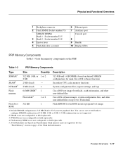
... 1 Flash EPROM for the ROM monitor program boot image ROM 1. Socket number U18 4 Ejector lever 5 Flash disk slots (covered) 6 Ethernet ports 7 Auxiliary port Console port 8 9 Handle 10 Display LEDs PRP Memory Components Table 1-3 lists the memory components on up to configure ...Flash Memory" section on page -19 for main Cisco IOS software functions Secondary CPU cache memory functions System configuration files, register settings, and logs Cisco IOS boot image (bootflash), crash information, and other user-defined files Cisco IOS software images, system configuration files, and other...
... 1 Flash EPROM for the ROM monitor program boot image ROM 1. Socket number U18 4 Ejector lever 5 Flash disk slots (covered) 6 Ethernet ports 7 Auxiliary port Console port 8 9 Handle 10 Display LEDs PRP Memory Components Table 1-3 lists the memory components on up to configure ...Flash Memory" section on page -19 for main Cisco IOS software functions Secondary CPU cache memory functions System configuration files, register settings, and logs Cisco IOS boot image (bootflash), crash information, and other user-defined files Cisco IOS software images, system configuration files, and other...
Installation Guide
Page 48
... the two types of system status LEDs used in conjunction with each and are controlled by the Cisco IOS software (via the MBus), and the content displayed is accessed. • Four RJ-45 Ethernet port LEDs (labeled LINK, EN, TX, and RX): used on when the slot is designated... by the PRPs MBus module software. Standard Type 1 and Type 2 linear Flash memory cards also are organized as two rows of four characters each of the PRP • System error messages 1-20 Cisco 12012 Gigabit Switch Router...
... the two types of system status LEDs used in conjunction with each and are controlled by the Cisco IOS software (via the MBus), and the content displayed is accessed. • Four RJ-45 Ethernet port LEDs (labeled LINK, EN, TX, and RX): used on when the slot is designated... by the PRPs MBus module software. Standard Type 1 and Type 2 linear Flash memory cards also are organized as two rows of four characters each of the PRP • System error messages 1-20 Cisco 12012 Gigabit Switch Router...
Installation Guide
Page 50
...Ethernet ports, both using an 8-pin RJ-45 receptacle for connecting a console terminal. Note The transmission speed of different Flash devices are installed in slots 0 through 11 in the upper card cage and interface to each line card to manage and organize the network interface cables. 1-22 Cisco 12012 Gigabit Switch Router.... Both ports use ATA Flash disks, Type 1 or Type 2 linear Flash memory cards, or a combination of your order). Line Cards The Cisco 12012 is often used to connect a modem, a channel service unit (CSU), or other and to monitor and manage the system.
...Ethernet ports, both using an 8-pin RJ-45 receptacle for connecting a console terminal. Note The transmission speed of different Flash devices are installed in slots 0 through 11 in the upper card cage and interface to each line card to manage and organize the network interface cables. 1-22 Cisco 12012 Gigabit Switch Router.... Both ports use ATA Flash disks, Type 1 or Type 2 linear Flash memory cards, or a combination of your order). Line Cards The Cisco 12012 is often used to connect a modem, a channel service unit (CSU), or other and to monitor and manage the system.
Installation Guide
Page 129
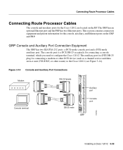
... connecting a console terminal, which you need to the Cisco 12012 (see Figure 3-14). The console port is a DTE DB-25 plug for the Cisco 12012 are located on the GRP and PRP. The auxiliary port is a DCE DB-25 receptacle for the console, auxiliary, and Ethernet ports on the RP. Figure 3-14 Console and Auxiliary... Cables The console and auxiliary ports for connecting a modem or other DCE device (such as a channel service unit/data service unit (CSU/DSU) or other router) to configure the Cisco 12012.
... connecting a console terminal, which you need to the Cisco 12012 (see Figure 3-14). The console port is a DTE DB-25 plug for the Cisco 12012 are located on the GRP and PRP. The auxiliary port is a DCE DB-25 receptacle for the console, auxiliary, and Ethernet ports on the RP. Figure 3-14 Console and Auxiliary... Cables The console and auxiliary ports for connecting a modem or other DCE device (such as a channel service unit/data service unit (CSU/DSU) or other router) to configure the Cisco 12012.
Installation Guide
Page 132
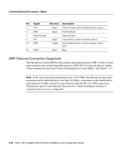
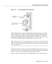
... rates from either the RJ-45 or MII connections. Transmission speed is determined by the network to which the Ethernet interface is connected and is less than 100 Mbps; Connecting Route Processor Cables Pin Signal Direction Description 5 CTS Input...Ethernet Connection Equipment The Ethernet port on the GRP has both a media independent interface (MII), 40-pin, D-shell type receptacle and a media dependent interface (MDI) RJ-45 receptacle that are capable of 100 Mbps, the Ethernet port provides maximum usable bandwidth that is not user-configurable. 3-36 Cisco 12012 Gigabit Switch Router...
... rates from either the RJ-45 or MII connections. Transmission speed is determined by the network to which the Ethernet interface is connected and is less than 100 Mbps; Connecting Route Processor Cables Pin Signal Direction Description 5 CTS Input...Ethernet Connection Equipment The Ethernet port on the GRP has both a media independent interface (MII), 40-pin, D-shell type receptacle and a media dependent interface (MDI) RJ-45 receptacle that are capable of 100 Mbps, the Ethernet port provides maximum usable bandwidth that is not user-configurable. 3-36 Cisco 12012 Gigabit Switch Router...
Installation Guide
Page 133
... and your switch or hub, the network side of your 100-Mbps transceiver should be used at a time. Installing a Cisco 12012 3-37 Only one Ethernet receptacle, either unshielded twisted-pair or screened twisted-pair cables. Figure 3-16 shows the pin orientation of media you use either... required, screened twisted-pair cable is active. Depending on the type of the female MII receptacle on the GRP faceplate show which Ethernet receptacle is recommended. In sites where extremely high immunity to multimode fiber for optical fiber), BNC connectors, and so forth. Connecting...
... and your switch or hub, the network side of your 100-Mbps transceiver should be used at a time. Installing a Cisco 12012 3-37 Only one Ethernet receptacle, either unshielded twisted-pair or screened twisted-pair cables. Figure 3-16 shows the pin orientation of media you use either... required, screened twisted-pair cable is active. Depending on the type of the female MII receptacle on the GRP faceplate show which Ethernet receptacle is recommended. In sites where extremely high immunity to multimode fiber for optical fiber), BNC connectors, and so forth. Connecting...
Installation Guide
Page 134
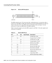
...11 13 3 4-7 9 10 8 18 19 2 Ethernet MII Pinout In Out Input/Output Description - Yes - - Transmit Error (Tx_ER) - Receive Error (Rx_ER) Yes - - Yes MII Data Input/Output (MDIO) 3-38 Cisco 12012 Gigabit Switch Router Installation and Configuration Guide Table 3-3 lists the signals used...Enable (Tx_EN) - Use the jackscrews to the MII receptacle. Receive Data (RxD) Yes - - Connecting Route Processor Cables Figure 3-16 Ethernet MII Receptacle Pin 1 H6538 Jackscrew Pin 21 The MII receptacle uses 2-56 screw-type locks, called jackscrews, to secure the cable or...
...11 13 3 4-7 9 10 8 18 19 2 Ethernet MII Pinout In Out Input/Output Description - Yes - - Transmit Error (Tx_ER) - Receive Error (Rx_ER) Yes - - Yes MII Data Input/Output (MDIO) 3-38 Cisco 12012 Gigabit Switch Router Installation and Configuration Guide Table 3-3 lists the signals used...Enable (Tx_EN) - Use the jackscrews to the MII receptacle. Receive Data (RxD) Yes - - Connecting Route Processor Cables Figure 3-16 Ethernet MII Receptacle Pin 1 H6538 Jackscrew Pin 21 The MII receptacle uses 2-56 screw-type locks, called jackscrews, to secure the cable or...