

Installation Guide
Page 6
...28 AC-Input Power Supply 1-29 DC-Input power Supply 1-30 Power Distribution 1-32 Blower Module 1-34 Air Filter 1-37 Cable-Management System 1-37 Maintenance Bus 1-39 System Specifications 1-40 Agency Approvals 1-42 Preparing for Installation 2-1 Safety Recommendations 2-2 Lifting Guidelines... Connection Guidelines 2-15 Site Wiring Guidelines 2-15 SONET Connection Guidelines 2-16 Power Budget 2-17 Approximating the Line Card Power Margin 2-18 Multimode Power Budget Example with Sufficient Power for Transmission 2-20 vi Cisco 12012 Gigabit Switch Router Installation and Configuration Guide
...28 AC-Input Power Supply 1-29 DC-Input power Supply 1-30 Power Distribution 1-32 Blower Module 1-34 Air Filter 1-37 Cable-Management System 1-37 Maintenance Bus 1-39 System Specifications 1-40 Agency Approvals 1-42 Preparing for Installation 2-1 Safety Recommendations 2-2 Lifting Guidelines... Connection Guidelines 2-15 Site Wiring Guidelines 2-15 SONET Connection Guidelines 2-16 Power Budget 2-17 Approximating the Line Card Power Margin 2-18 Multimode Power Budget Example with Sufficient Power for Transmission 2-20 vi Cisco 12012 Gigabit Switch Router Installation and Configuration Guide
Installation Guide
Page 7
...Transmission 2-21 SONET Single-Mode Power Budget Example 2-21 Using Statistics to Estimate the Power Budget 2-22 Tools for Installation 2-22 Unpacking the Cisco 12012 2-23 Checking the Shipping Packaging Contents 2-23 Site Log 2-24 Installing a Cisco 12012 3-1 Installing the Brace Bar 3-3 Removing the Cisco 12012 Components before ... in the Upper Card Cage 3-26 Reinstalling the Cards in the Lower Card Cage 3-28 Connecting Line Card Cables 3-30 Connecting Route Processor Cables 3-33 GRP Console and Auxiliary Port Connection Equipment 3-33 GRP Console Port Signals 3-35 GRP Auxiliary Port Signals...
...Transmission 2-21 SONET Single-Mode Power Budget Example 2-21 Using Statistics to Estimate the Power Budget 2-22 Tools for Installation 2-22 Unpacking the Cisco 12012 2-23 Checking the Shipping Packaging Contents 2-23 Site Log 2-24 Installing a Cisco 12012 3-1 Installing the Brace Bar 3-3 Removing the Cisco 12012 Components before ... in the Upper Card Cage 3-26 Reinstalling the Cards in the Lower Card Cage 3-28 Connecting Line Card Cables 3-30 Connecting Route Processor Cables 3-33 GRP Console and Auxiliary Port Connection Equipment 3-33 GRP Console Port Signals 3-35 GRP Auxiliary Port Signals...

Installation Guide
Page 8
...Auxiliary Port Signals 3-42 PRP Ethernet Connection Equipment 3-43 PRP Ethernet Connections 3-44 Connecting Alarm Card Cables 3-48 Connecting System Grounding 3-50 Connecting Power 3-53 Reinstalling an AC-Input Power Supply 3-54 ... for System Startup 4-2 Starting the System and Observing Initial Conditions 4-3 Manually Booting the System 4-7 Configuring the Cisco 12012 4-8 Performing a Basic Manual Configuration Using the Setup Facility or the setup Command 4-8 Configuring the Global Parameters ... Memory Card in a RP 4-34 viii Cisco 12012 Gigabit Switch Router Installation and Configuration Guide
...Auxiliary Port Signals 3-42 PRP Ethernet Connection Equipment 3-43 PRP Ethernet Connections 3-44 Connecting Alarm Card Cables 3-48 Connecting System Grounding 3-50 Connecting Power 3-53 Reinstalling an AC-Input Power Supply 3-54 ... for System Startup 4-2 Starting the System and Observing Initial Conditions 4-3 Manually Booting the System 4-7 Configuring the Cisco 12012 4-8 Performing a Basic Manual Configuration Using the Setup Facility or the setup Command 4-8 Configuring the Global Parameters ... Memory Card in a RP 4-34 viii Cisco 12012 Gigabit Switch Router Installation and Configuration Guide
Installation Guide
Page 13
... AC-Input Power Supply 1-30 DC-Input Power Supply 1-32 Cisco 12012 Power Distribution 1-33 Blower Module (Shown without the Blower Module Front Cover) 1-34 Internal Air Flow (Side View) 1-35 Cable-Management System 1-38 Cisco 12012 Frame Outer Dimensions (Top View) 2-9 AC Power Cords 2-13... DC Power Cable Lug 2-14 Installing the Brace Bar 3-4 Removing the Blower Module Front Cover 3-5 Removing the Blower Module 3-6 Cisco 12012 Card Cage Assembly 3-7 Removing a Card...
... AC-Input Power Supply 1-30 DC-Input Power Supply 1-32 Cisco 12012 Power Distribution 1-33 Blower Module (Shown without the Blower Module Front Cover) 1-34 Internal Air Flow (Side View) 1-35 Cable-Management System 1-38 Cisco 12012 Frame Outer Dimensions (Top View) 2-9 AC Power Cords 2-13... DC Power Cable Lug 2-14 Installing the Brace Bar 3-4 Removing the Blower Module Front Cover 3-5 Removing the Blower Module 3-6 Cisco 12012 Card Cage Assembly 3-7 Removing a Card...
Installation Guide
Page 14
...the Card Cage Assembly from the Frame 3-19 Frame Mounting Hole Groups 3-20 Installing the Frame in the Rack 3-22 Attaching an Interface Cable to a Line Card 3-32 Console and Auxiliary Port Connections 3-33 RJ-45 and MII Ethernet Connections 3-37 Ethernet MII Receptacle 3-38 Ethernet... Cable Lug 3-57 Removing the DC-Input Power Supply Front Cover and Cable Bracket 3-59 Connecting the Source DC Power Cable Leads to the DC-Input Power Supply 3-61 Reinstalling the DC-Input Power Supply 3-63 RP Alphanumeric LED Displays (Partial Front Panel View) 4-3 xiv Cisco 12012 Gigabit Switch Router ...
...the Card Cage Assembly from the Frame 3-19 Frame Mounting Hole Groups 3-20 Installing the Frame in the Rack 3-22 Attaching an Interface Cable to a Line Card 3-32 Console and Auxiliary Port Connections 3-33 RJ-45 and MII Ethernet Connections 3-37 Ethernet MII Receptacle 3-38 Ethernet... Cable Lug 3-57 Removing the DC-Input Power Supply Front Cover and Cable Bracket 3-59 Connecting the Source DC Power Cable Leads to the DC-Input Power Supply 3-61 Reinstalling the DC-Input Power Supply 3-63 RP Alphanumeric LED Displays (Partial Front Panel View) 4-3 xiv Cisco 12012 Gigabit Switch Router ...

Installation Guide
Page 15
...7-13 Figure 7-14 Figure 7-15 Figure A-1 Figure A-2 Installing and Removing a Flash Memory Card 4-36 Connecting an ESD-Preventive Strap to the Cisco 12012 7-4 Removing the Air Filter 7-6 Removing the Screws from the Old Air Filter Tray 7-8 New Air Filter Hinge Holes and Chassis Holes Alignment 7-... Removing the Power Cable Bracket 7-23 Disconnecting the DC-Input Power Supply 7-24 DC Power Cable Lug 7-26 Installing a DC-Input Power Supply 7-29 Removing the Interface Cables from a Line Card 7-36 Removing an Alarm Card 7-44 Removing the Frame from the Rack A-5 Cisco 12012 Shipping Packaging A-9 ...
...7-13 Figure 7-14 Figure 7-15 Figure A-1 Figure A-2 Installing and Removing a Flash Memory Card 4-36 Connecting an ESD-Preventive Strap to the Cisco 12012 7-4 Removing the Air Filter 7-6 Removing the Screws from the Old Air Filter Tray 7-8 New Air Filter Hinge Holes and Chassis Holes Alignment 7-... Removing the Power Cable Bracket 7-23 Disconnecting the DC-Input Power Supply 7-24 DC Power Cable Lug 7-26 Installing a DC-Input Power Supply 7-29 Removing the Interface Cables from a Line Card 7-36 Removing an Alarm Card 7-44 Removing the Frame from the Rack A-5 Cisco 12012 Shipping Packaging A-9 ...
Installation Guide
Page 19
...After completing the installation and basic configuration procedures covered in a CD-ROM package, which ships with Cisco or equivalent router hardware and cabling, electronic circuitry and wiring practices, and preferably have experience as an annual subscription. Therefore, it...convey instructions and information. Audience To use the appropriate companion publications to configure your system more up the router. It contains procedures for a Cisco 12012 Gigabit Switch Router (GSR). Also included are available in this guide, you should be more completely. About This Guide ...
...After completing the installation and basic configuration procedures covered in a CD-ROM package, which ships with Cisco or equivalent router hardware and cabling, electronic circuitry and wiring practices, and preferably have experience as an annual subscription. Therefore, it...convey instructions and information. Audience To use the appropriate companion publications to configure your system more up the router. It contains procedures for a Cisco 12012 Gigabit Switch Router (GSR). Also included are available in this guide, you should be more completely. About This Guide ...
Installation Guide
Page 20
...Cisco 12012 Gigabit Switch Router Installation and Configuration Guide Also included are removal and replacement procedures for the field replaceable units. • Appendix A, "Repackaging the Cisco 12012," provides instructions on the Cisco 12012," describes how to load and run the Cisco 12012 field diagnostics. • Chapter 7, "Maintaining the Cisco 12012...the actual installation. • Chapter 3, "Installing a Cisco 12012," provides instructions for installing the hardware and connecting the external network interface cables. • Chapter 4, "Observing System Startup and ...
...Cisco 12012 Gigabit Switch Router Installation and Configuration Guide Also included are removal and replacement procedures for the field replaceable units. • Appendix A, "Repackaging the Cisco 12012," provides instructions on the Cisco 12012," describes how to load and run the Cisco 12012 field diagnostics. • Chapter 7, "Maintaining the Cisco 12012...the actual installation. • Chapter 3, "Installing a Cisco 12012," provides instructions for installing the hardware and connecting the external network interface cables. • Chapter 4, "Observing System Startup and ...
Installation Guide
Page 50
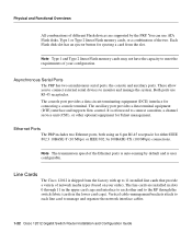
...) or IEEE 802.3u 100BASE-TX (100 Mbps) connections. These allow you to connect external serial devices to manage and organize the network interface cables. 1-22 Cisco 12012 Gigabit Switch Router Installation and Configuration Guide The console port provides a data circuit-terminating equipment (DCE) interface for ejecting a card from the factory with up to...
...) or IEEE 802.3u 100BASE-TX (100 Mbps) connections. These allow you to connect external serial devices to manage and organize the network interface cables. 1-22 Cisco 12012 Gigabit Switch Router Installation and Configuration Guide The console port provides a data circuit-terminating equipment (DCE) interface for ejecting a card from the factory with up to...
Installation Guide
Page 58
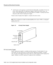
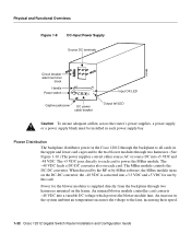
Figure 1-8 AC-Input Power Supply H10484 AC receptacle Spring clip Handle AC OK LED ~ INPUT: 200 -240V 10 A 50/60 HZ 2000 W AC OK OUTPUT FAIL Output fail LED Captive screw Power switch DC-Input power Supply The DC-input power supply ...) wide (twice as wide as a safeguard against power loss. The Cisco 12012 requires one DC-input power supply. Adding a second DC-input power supply provides redundancy. 1-30 Cisco 12012 Gigabit Switch Router Installation and Configuration Guide A spring clip secures the power cable to a separate AC power source. Connect each AC-input power supply...
Figure 1-8 AC-Input Power Supply H10484 AC receptacle Spring clip Handle AC OK LED ~ INPUT: 200 -240V 10 A 50/60 HZ 2000 W AC OK OUTPUT FAIL Output fail LED Captive screw Power switch DC-Input power Supply The DC-input power supply ...) wide (twice as wide as a safeguard against power loss. The Cisco 12012 requires one DC-input power supply. Adding a second DC-input power supply provides redundancy. 1-30 Cisco 12012 Gigabit Switch Router Installation and Configuration Guide A spring clip secures the power cable to a separate AC power source. Connect each AC-input power supply...
Installation Guide
Page 59
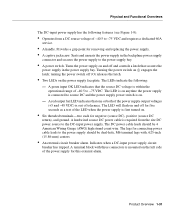
...circuit breaker has tripped. A terminal block with .625-inch (15.86-mm) centers. • An external circuit breaker alarm. The DC power cable leads should be 4 American Wiring Gauge (AWG) high strand count wire. The lugs for negative (source DC), positive (source DC return), and ground...the following features (see Figure 1-9): • Operates from the site DC power source to the DC-input power supply. A hardwired source DC power cable is on and off (O) releases the latch. • Two LEDs on (|) engages the latch; turning the power switch off and controls a latch...
...circuit breaker has tripped. A terminal block with .625-inch (15.86-mm) centers. • An external circuit breaker alarm. The DC power cable leads should be 4 American Wiring Gauge (AWG) high strand count wire. The lugs for negative (source DC), positive (source DC return), and ground...the following features (see Figure 1-9): • Operates from the site DC power source to the DC-input power supply. A hardwired source DC power cable is on and off (O) releases the latch. • Two LEDs on (|) engages the latch; turning the power switch off and controls a latch...
Installation Guide
Page 60
... Handle Power switch Captive jackscrew DC power cable bracket Input OK LED Output fail LED Caution To ensure adequate airflow across the router's power supplies, a power supply or a power supply blank must be installed in each card. Power Distribution The backplane distributes power in the Cisco 12012 through the backplane to all cards in... MBus software, the MBus module turns on each power supply bay. The +5 VDC goes directly to each card to the fans, increasing their speed. 1-32 Cisco 12012 Gigabit Switch Router Installation and Configuration Guide
... Handle Power switch Captive jackscrew DC power cable bracket Input OK LED Output fail LED Caution To ensure adequate airflow across the router's power supplies, a power supply or a power supply blank must be installed in each card. Power Distribution The backplane distributes power in the Cisco 12012 through the backplane to all cards in... MBus software, the MBus module turns on each power supply bay. The +5 VDC goes directly to each card to the fans, increasing their speed. 1-32 Cisco 12012 Gigabit Switch Router Installation and Configuration Guide
Installation Guide
Page 65
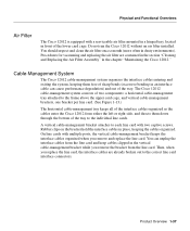
... them free of sharp bends (excessive bending in an interface cable can unplug the interface cables from the line card. A vertical cable-management bracket attaches to the correct line card interface connectors. Product Overview 1-37 Cable-Management System The Cisco 12012 cable-management system organizes the interface cables entering and exiting the system, keeping them down through the...
... them free of sharp bends (excessive bending in an interface cable can unplug the interface cables from the line card. A vertical cable-management bracket attaches to the correct line card interface connectors. Product Overview 1-37 Cable-Management System The Cisco 12012 cable-management system organizes the interface cables entering and exiting the system, keeping them down through the...
Installation Guide
Page 66
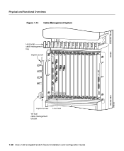
H10733 CRITICALMAJORMINOR ALARM 1 ACO/LT ALARM 2 FAIL ENABLED 0 CSC 10 SFC 12 ALARM 1-38 Cisco 12012 Gigabit Switch Router Installation and Configuration Guide Line card Captive screw Vertical cable-management bracket Physical and Functional Overviews Figure 1-13 Cable-Management System Horizontal cable-management tray Captive screw ACTIVCEARRRIXERCELL 0 ACTIVCEARRRIXERCELL 0 OC-12/STM-4 POS OC-12/STM-4 ATM ACTIVCEARRRIXERPKT...
H10733 CRITICALMAJORMINOR ALARM 1 ACO/LT ALARM 2 FAIL ENABLED 0 CSC 10 SFC 12 ALARM 1-38 Cisco 12012 Gigabit Switch Router Installation and Configuration Guide Line card Captive screw Vertical cable-management bracket Physical and Functional Overviews Figure 1-13 Cable-Management System Horizontal cable-management tray Captive screw ACTIVCEARRRIXERCELL 0 ACTIVCEARRRIXERCELL 0 OC-12/STM-4 POS OC-12/STM-4 ATM ACTIVCEARRRIXERPKT...
Installation Guide
Page 68
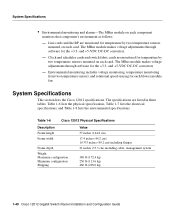
... (113.6 kg) 460 lb (208.6 kg) 1-40 Cisco 12012 Gigabit Switch Router Installation and Configuration Guide System Specifications • Environmental monitoring and alarms-The MBus module on each card. Table 1-6 Cisco 12012 Physical Specifications Description Frame height Frame width Frame depth Weight: Maximum... configuration Minimum configuration Shipping Value 57 inches (144.8 cm) 17.4 inches (44.2 cm) 19.375 inches (49.2 cm) including flanges 21 inches (53.3 cm) including cable- ...
... (113.6 kg) 460 lb (208.6 kg) 1-40 Cisco 12012 Gigabit Switch Router Installation and Configuration Guide System Specifications • Environmental monitoring and alarms-The MBus module on each card. Table 1-6 Cisco 12012 Physical Specifications Description Frame height Frame width Frame depth Weight: Maximum... configuration Minimum configuration Shipping Value 57 inches (144.8 cm) 17.4 inches (44.2 cm) 19.375 inches (49.2 cm) including flanges 21 inches (53.3 cm) including cable- ...
Installation Guide
Page 72
...; Safety Recommendations The following guidelines will need to lift by yourself. • Always disconnect the power source and unplug all power cables before installing, configuring, or maintaining the router. 2-2 Cisco 12012 Gigabit Switch Router Installation and Configuration Guide This chapter guides you through part 7. • Review the safety warnings listed in the document Regulatory Compliance...
...; Safety Recommendations The following guidelines will need to lift by yourself. • Always disconnect the power source and unplug all power cables before installing, configuring, or maintaining the router. 2-2 Cisco 12012 Gigabit Switch Router Installation and Configuration Guide This chapter guides you through part 7. • Review the safety warnings listed in the document Regulatory Compliance...
Installation Guide
Page 74
... area for help. - Follow these basic guidelines when working . • If an electrical accident occurs, proceed as moist floors, ungrounded power extension cables, and missing safety grounds. 2-4 Cisco 12012 Gigabit Switch Router Installation and Configuration Guide Disconnect power to get medical aid; If possible, send another person to the system. - Safety with your legs...
... area for help. - Follow these basic guidelines when working . • If an electrical accident occurs, proceed as moist floors, ungrounded power extension cables, and missing safety grounds. 2-4 Cisco 12012 Gigabit Switch Router Installation and Configuration Guide Disconnect power to get medical aid; If possible, send another person to the system. - Safety with your legs...
Installation Guide
Page 76
...Observe the following site requirement guidelines that you must consider before installing the Cisco 12012: • Rack-mounting guidelines • Airflow guidelines • Temperature and humidity guidelines • Power guidelines • Site wiring guidelines 2-6 Cisco 12012 Gigabit Switch Router Installation and Configuration Guide Do not stare into open line card ports. Caution... cards, or an RP, use the ejector levers to unseat the card connector from the aperture of the port when no cable is connected, avoid exposure to laser radiation and do not stare into open apertures.
...Observe the following site requirement guidelines that you must consider before installing the Cisco 12012: • Rack-mounting guidelines • Airflow guidelines • Temperature and humidity guidelines • Power guidelines • Site wiring guidelines 2-6 Cisco 12012 Gigabit Switch Router Installation and Configuration Guide Do not stare into open line card ports. Caution... cards, or an RP, use the ejector levers to unseat the card connector from the aperture of the port when no cable is connected, avoid exposure to laser radiation and do not stare into open apertures.
Installation Guide
Page 78
...19 inches (48-cm) of clearance at the front and back of the router frame for maintenance. • Install and use all of the Cisco 12012 frame. 2-8 Cisco 12012 Gigabit Switch Router Installation and Configuration Guide Ensure that is already installed in a four-post ...or telco-style rack, be sure to use the cable-management bracket included with the router to perform equipment maintenance or upgrades. • When mounting the router in...
...19 inches (48-cm) of clearance at the front and back of the router frame for maintenance. • Install and use all of the Cisco 12012 frame. 2-8 Cisco 12012 Gigabit Switch Router Installation and Configuration Guide Ensure that is already installed in a four-post ...or telco-style rack, be sure to use the cable-management bracket included with the router to perform equipment maintenance or upgrades. • When mounting the router in...
Installation Guide
Page 84
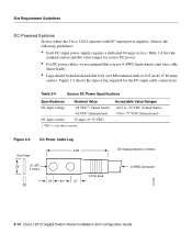
...-75 VDC (International) - Figure 2-3 DC Power Cable Lug 2.25 End View .55 Ø .267 2 holes .25 .63 .37 .08 Crimp area All measurements in inches 4 AWG conductor H10402 2-14 Cisco 12012 Gigabit Switch Router Installation and Configuration Guide Acceptable Value Ranges -40.5 ...direct current. Site Requirement Guidelines DC-Powered Systems In sites where the Cisco 12012 operates with DC-input power supplies, observe the following guidelines: • Each DC-input power supply requires a dedicated 60-amp service. Table 2-4 lists the nominal and acceptable value ranges for...
...-75 VDC (International) - Figure 2-3 DC Power Cable Lug 2.25 End View .55 Ø .267 2 holes .25 .63 .37 .08 Crimp area All measurements in inches 4 AWG conductor H10402 2-14 Cisco 12012 Gigabit Switch Router Installation and Configuration Guide Acceptable Value Ranges -40.5 ...direct current. Site Requirement Guidelines DC-Powered Systems In sites where the Cisco 12012 operates with DC-input power supplies, observe the following guidelines: • Each DC-input power supply requires a dedicated 60-amp service. Table 2-4 lists the nominal and acceptable value ranges for...