
Installation Guide
Page 3
...Purpose ix Conventions ix Related Publications x Obtaining Documentation, Obtaining Support, and Security Guidelines x Overview 1-1 Overview 1-1 Switch Models 1-2 Front-Panel Description 1-2 10/100 Ports 1-5 Dual-Purpose Ports 1-5 100BASE-FX Ports 1-5 Power and Relay Connector 1-5 Console Port 1-6 LEDs 1-6 Setup ...Purpose Port LEDs 1-11 Compact Flash Memory Card 1-11 Rear-Panel Description 1-12 Power Converter (Optional) 1-13 Management Options 1-14 Network Configurations 1-15 Switch Installation 2-1 Preparing for Installation 2-1 Warnings 2-2 Cisco IE 3000 Switch Hardware Installation Guide iii
...Purpose ix Conventions ix Related Publications x Obtaining Documentation, Obtaining Support, and Security Guidelines x Overview 1-1 Overview 1-1 Switch Models 1-2 Front-Panel Description 1-2 10/100 Ports 1-5 Dual-Purpose Ports 1-5 100BASE-FX Ports 1-5 Power and Relay Connector 1-5 Console Port 1-6 LEDs 1-6 Setup ...Purpose Port LEDs 1-11 Compact Flash Memory Card 1-11 Rear-Panel Description 1-12 Power Converter (Optional) 1-13 Management Options 1-14 Network Configurations 1-15 Switch Installation 2-1 Preparing for Installation 2-1 Warnings 2-2 Cisco IE 3000 Switch Hardware Installation Guide iii
Installation Guide
Page 11
...industrial enclosure, on a wall or panel, and with some restrictions, in a standard 19-inch rack. OL-13017-01 Cisco IE 3000 Switch Hardware Installation Guide 1-1 Note The switch does not have cooling fans. You can connect any Ethernet-enabled industrial communication...page 1-2 • Front-Panel Description, page 1-2 • Compact Flash Memory Card, page 1-11 • Rear-Panel Description, page 1-12 • Power Converter (Optional), page 1-13 • Management Options, page 1-14 • Network Configurations, page 1-15 Overview The Cisco IE 3000 switch provides a rugged and secure...
...industrial enclosure, on a wall or panel, and with some restrictions, in a standard 19-inch rack. OL-13017-01 Cisco IE 3000 Switch Hardware Installation Guide 1-1 Note The switch does not have cooling fans. You can connect any Ethernet-enabled industrial communication...page 1-2 • Front-Panel Description, page 1-2 • Compact Flash Memory Card, page 1-11 • Rear-Panel Description, page 1-12 • Power Converter (Optional), page 1-13 • Management Options, page 1-14 • Network Configurations, page 1-15 Overview The Cisco IE 3000 switch provides a rugged and secure...

Installation Guide
Page 12
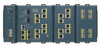
... and expansion module front panels. The Cisco IE-3000-4TC and the Cisco IE-3000-8TC are the switch models, and the Cisco IEM-3000-8TM and the Cisco IEM-3000-8FM are expansion modules that you can connect to increase the number of ports. Table 1-1 Cisco IE 3000 Switch Models Switch Model Cisco IE-3000-4TC Cisco IE-3000-8TC Cisco IEM-3000-8TM Cisco IEM-3000-8FM Description 4 10/100BASE-T Ethernet ports and 2 dual...
... and expansion module front panels. The Cisco IE-3000-4TC and the Cisco IE-3000-8TC are the switch models, and the Cisco IEM-3000-8TM and the Cisco IEM-3000-8FM are expansion modules that you can connect to increase the number of ports. Table 1-1 Cisco IE 3000 Switch Models Switch Model Cisco IE-3000-4TC Cisco IE-3000-8TC Cisco IEM-3000-8TM Cisco IEM-3000-8FM Description 4 10/100BASE-T Ethernet ports and 2 dual...

Installation Guide
Page 13
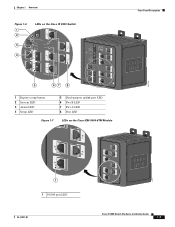
Chapter 1 Overview Figure 1-1 Cisco IE-3000-8TC Switch 1 2 Front-Panel Description 201699 3 45 1 Power and relay connectors 4 10/100 ports 2 Console port 5 Protective ground connection 3 Dual-purpose ports Figure 1-2 Cisco IE-3000-4TC Switch 1 2 201700 3 45 1 Power and relay connectors 4 2 Console port 5 3 Dual-purpose ports 10/100 ports Protective ground connection OL-13017-01 Cisco IE 3000 Switch Hardware Installation Guide 1-3
Chapter 1 Overview Figure 1-1 Cisco IE-3000-8TC Switch 1 2 Front-Panel Description 201699 3 45 1 Power and relay connectors 4 10/100 ports 2 Console port 5 Protective ground connection 3 Dual-purpose ports Figure 1-2 Cisco IE-3000-4TC Switch 1 2 201700 3 45 1 Power and relay connectors 4 2 Console port 5 3 Dual-purpose ports 10/100 ports Protective ground connection OL-13017-01 Cisco IE 3000 Switch Hardware Installation Guide 1-3

Installation Guide
Page 15
...left side of the attached device and advertises its own capabilities. See Figure 1-2. OL-13017-01 Cisco IE 3000 Switch Hardware Installation Guide 1-5 You can also set these SFP modules, see the switch software configuration...connectors to connect to the switch through cable. The cable can be up to workstations, servers, routers, and Cisco IP Phones, be within 328 feet (100 meters). 100BASE-TX traffic requires Category 5 cable. 10BASE-T traffic ...SFP module port. Chapter 1 Overview Front-Panel Description 10/100 Ports You can set the 10/100 ports to other switches.
...left side of the attached device and advertises its own capabilities. See Figure 1-2. OL-13017-01 Cisco IE 3000 Switch Hardware Installation Guide 1-5 You can also set these SFP modules, see the switch software configuration...connectors to connect to the switch through cable. The cable can be up to workstations, servers, routers, and Cisco IP Phones, be within 328 feet (100 meters). 100BASE-TX traffic requires Category 5 cable. 10BASE-T traffic ...SFP module port. Chapter 1 Overview Front-Panel Description 10/100 Ports You can set the 10/100 ports to other switches.

Installation Guide
Page 16
...power source or with one of the two power sources fail, the other continues to monitor the switch status, activity, and performance. Cisco IE 3000 Switch Hardware Installation Guide 1-6 OL-13017-01 The positive DC power connection is labeled V, and the return connection is normally open, so...Port You can order a kit (part number ACS-DSBUASYN=) with that adapter from the DC source with either open . Front-Panel Description Chapter 1 Overview The switch accessory pack includes the mating power and relay connectors. See the switch software configuration guide for terminating the...
...power source or with one of the two power sources fail, the other continues to monitor the switch status, activity, and performance. Cisco IE 3000 Switch Hardware Installation Guide 1-6 OL-13017-01 The positive DC power connection is labeled V, and the return connection is normally open, so...Port You can order a kit (part number ACS-DSBUASYN=) with that adapter from the DC source with either open . Front-Panel Description Chapter 1 Overview The switch accessory pack includes the mating power and relay connectors. See the switch software configuration guide for terminating the...
Installation Guide
Page 17
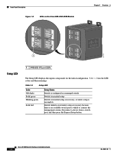
Chapter 1 Overview Figure 1-6 1 2 3 4 LEDs on the Cisco IE 3000 Switch Front-Panel Description 201703 5 67 8 1 Express setup button 2 System LED 3 Alarm LED 4 Setup LED 5 Dual-purpose uplink port LED 6 Pwr B LED 7 Pwr A LED 8 Port LED Figure 1-7 LEDs on the Cisco IEM-3000-8TM Module 201706 1 1 10/100 port LED OL-13017-01 Cisco IE 3000 Switch Hardware Installation Guide 1-7
Chapter 1 Overview Figure 1-6 1 2 3 4 LEDs on the Cisco IE 3000 Switch Front-Panel Description 201703 5 67 8 1 Express setup button 2 System LED 3 Alarm LED 4 Setup LED 5 Dual-purpose uplink port LED 6 Pwr B LED 7 Pwr A LED 8 Port LED Figure 1-7 LEDs on the Cisco IEM-3000-8TM Module 201706 1 1 10/100 port LED OL-13017-01 Cisco IE 3000 Switch Hardware Installation Guide 1-7
Installation Guide
Page 18
Switch is incomplete. Front-Panel Description Figure 1-8 LEDs on the Cisco IEM-3000-8FM Module Chapter 1 Overview 201705 1 Setup LED 1 100BASE -FX port LEDs The Setup LED displays the express setup mode for the initial configuration. Cisco IE 3000 Switch Hardware Installation Guide 1-8 OL-13017-01 Switch failed to start initial setup or recovery because there is...
Switch is incomplete. Front-Panel Description Figure 1-8 LEDs on the Cisco IEM-3000-8FM Module Chapter 1 Overview 201705 1 Setup LED 1 100BASE -FX port LEDs The Setup LED displays the express setup mode for the initial configuration. Cisco IE 3000 Switch Hardware Installation Guide 1-8 OL-13017-01 Switch failed to start initial setup or recovery because there is...

Installation Guide
Page 19
... Off Green Red System Status Power is not present on the circuit, or the system is functioning properly. Chapter 1 Overview Front-Panel Description System LED The System LED shows whether the system is receiving power and is not powered up. Table 1-3 System LED Color Off Green... not configured, or the switch is not powered on the alarm configuration. If power is present on the associated circuit. OL-13017-01 Cisco IE 3000 Switch Hardware Installation Guide 1-9 System is green. Alarm LED Table 1-4 lists the alarm LED colors and their meanings. If power is present...
... Off Green Red System Status Power is not present on the circuit, or the system is functioning properly. Chapter 1 Overview Front-Panel Description System LED The System LED shows whether the system is receiving power and is not powered up. Table 1-3 System LED Color Off Green... not configured, or the switch is not powered on the alarm configuration. If power is present on the associated circuit. OL-13017-01 Cisco IE 3000 Switch Hardware Installation Guide 1-9 System is green. Alarm LED Table 1-4 lists the alarm LED colors and their meanings. If power is present...

Installation Guide
Page 20
...FX MM Uplink Port Status LEDs Color Off Solid green Blinking green Blinking amber Alternating green-amber Solid amber System Status No link. Front-Panel Description Chapter 1 Overview Note The Pwr A and Pwr B LEDs show that power is present if the voltage at values near 18 V. For ...status LEDs only show that power is sending or receiving data. Blinking amber A link blocked by Spanning Tree Protocol (STP) is disabled. 1-10 Cisco IE 3000 Switch Hardware Installation Guide OL-13017-01 Port is not present on page 2-11. 10/100 Port Status LEDs Each 10/100 port has a ...
...FX MM Uplink Port Status LEDs Color Off Solid green Blinking green Blinking amber Alternating green-amber Solid amber System Status No link. Front-Panel Description Chapter 1 Overview Note The Pwr A and Pwr B LEDs show that power is present if the voltage at values near 18 V. For ...status LEDs only show that power is sending or receiving data. Blinking amber A link blocked by Spanning Tree Protocol (STP) is disabled. 1-10 Cisco IE 3000 Switch Hardware Installation Guide OL-13017-01 Port is not present on page 2-11. 10/100 Port Status LEDs Each 10/100 port has a ...
Installation Guide
Page 22
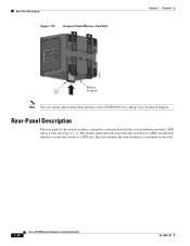
... switch Note You can obtain replacement flash memory cards (CF-IE3000=) by calling Cisco Technical Support. Rear-Panel Description Figure 1-10 Compact Flash Memory Card Slot Chapter 1 Overview 201832 Bottom 1 of the switch, modules, and power converter have latches for installation on the wall. 1-12 Cisco IE 3000 Switch Hardware Installation Guide OL-13017-01
... switch Note You can obtain replacement flash memory cards (CF-IE3000=) by calling Cisco Technical Support. Rear-Panel Description Figure 1-10 Compact Flash Memory Card Slot Chapter 1 Overview 201832 Bottom 1 of the switch, modules, and power converter have latches for installation on the wall. 1-12 Cisco IE 3000 Switch Hardware Installation Guide OL-13017-01
Installation Guide
Page 38
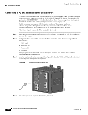
...needed. 2-12 Cisco IE 3000 Switch Hardware Installation Guide OL-13017-01 For console-port and adapter-pinout information, see the "Cable and Adapter Specifications" section on page C-4 for instructions. See the switch software configuration guide for pinout descriptions.) Figure 2-8 ...Connecting to the Console Port 201868 Step 4 Attach the appropriate adapter to the switch: Step 1 Step 2 Step 3 Make sure that adapter from Cisco. Follow these console-port default characteristics: •...
...needed. 2-12 Cisco IE 3000 Switch Hardware Installation Guide OL-13017-01 For console-port and adapter-pinout information, see the "Cable and Adapter Specifications" section on page C-4 for instructions. See the switch software configuration guide for pinout descriptions.) Figure 2-8 ...Connecting to the Console Port 201868 Step 4 Attach the appropriate adapter to the switch: Step 1 Step 2 Step 3 Make sure that adapter from Cisco. Follow these console-port default characteristics: •...
Installation Guide
Page 82
...or fiber-optic cable with power applied to the switch or any bad patch panel connections or media convertors between the source and destination. Cisco IE 3000 Switch Hardware Installation Guide 3-2 OL-13017-01 Enable auto-MDIX on the switch in another port or interface, if possible, to the ...for 10/100 or 10/100/1000 Mb/s connections. • Fiber-optic connectors Verify that the cable does not have the correct cable for a description of subtle damage to see the "Cable and Adapter Specifications" section on the network, an electrical arc can occur. See the "LEDs" section ...
...or fiber-optic cable with power applied to the switch or any bad patch panel connections or media convertors between the source and destination. Cisco IE 3000 Switch Hardware Installation Guide 3-2 OL-13017-01 Enable auto-MDIX on the switch in another port or interface, if possible, to the ...for 10/100 or 10/100/1000 Mb/s connections. • Fiber-optic connectors Verify that the cable does not have the correct cable for a description of subtle damage to see the "Cable and Adapter Specifications" section on the network, an electrical arc can occur. See the "LEDs" section ...
Installation Guide
Page 105
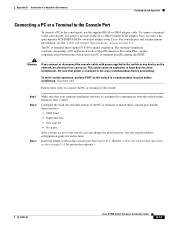
...to the switch: Step 1 Step 2 Step 3 Make sure that your PC or terminal possible during the POST. Be sure that adapter from Cisco. See Figure B-8. (See the "Cable and Adapter Specifications" section on page C-4. Appendix B Installation In a Hazardous Environment Verifying Switch Operation ...before proceeding. This could cause an explosion in the console port. See the switch software configuration guide for pinout descriptions.) OL-13017-01 Cisco IE 3000 Switch Hardware Installation Guide B-15 To connect a terminal to communicate with that power is removed or the area is...
...to the switch: Step 1 Step 2 Step 3 Make sure that your PC or terminal possible during the POST. Be sure that adapter from Cisco. See Figure B-8. (See the "Cable and Adapter Specifications" section on page C-4. Appendix B Installation In a Hazardous Environment Verifying Switch Operation ...before proceeding. This could cause an explosion in the console port. See the switch software configuration guide for pinout descriptions.) OL-13017-01 Cisco IE 3000 Switch Hardware Installation Guide B-15 To connect a terminal to communicate with that power is removed or the area is...

Installation Guide
Page 168
... to 2-43, B-46 to B-47 See 10/100 ports, 10/100/1000 ports, 100BASE-FX ports, 100BASE-LX ports, and console ports POST description 2-22, 2-53, 3-1, B-25, B-59 IN-4 Cisco IE 3000 Switch Hardware Installation Guide LEDs 3-1 results 2-22, 2-53, 3-1, B-25, B-59 running at power on 3-1 power connecting to AC 2-47, B-53 DC 2-16...
... to 2-43, B-46 to B-47 See 10/100 ports, 10/100/1000 ports, 100BASE-FX ports, 100BASE-LX ports, and console ports POST description 2-22, 2-53, 3-1, B-25, B-59 IN-4 Cisco IE 3000 Switch Hardware Installation Guide LEDs 3-1 results 2-22, 2-53, 3-1, B-25, B-59 running at power on 3-1 power connecting to AC 2-47, B-53 DC 2-16...

Software Configuration Guide
Page 13
... the Interface Speed and Duplex Parameters 13-14 Configuring IEEE 802.3x Flow Control 13-15 Configuring Auto-MDIX on an Interface 13-16 Adding a Description for an Interface 13-17 Configuring the System MTU 13-17 Monitoring and Maintaining the Interfaces 13-18 Monitoring Interface Status 13-19 Clearing and...-Range VLANs 15-4 Token Ring VLANs 15-5 Normal-Range VLAN Configuration Guidelines 15-5 VLAN Configuration Mode Options 15-6 VLAN Configuration in config-vlan Mode 15-6 Cisco IE 3000 Switch Software Configuration Guide xiii
... the Interface Speed and Duplex Parameters 13-14 Configuring IEEE 802.3x Flow Control 13-15 Configuring Auto-MDIX on an Interface 13-16 Adding a Description for an Interface 13-17 Configuring the System MTU 13-17 Monitoring and Maintaining the Interfaces 13-18 Monitoring Interface Status 13-19 Clearing and...-Range VLANs 15-4 Token Ring VLANs 15-5 Normal-Range VLAN Configuration Guidelines 15-5 VLAN Configuration Mode Options 15-6 VLAN Configuration in config-vlan Mode 15-6 Cisco IE 3000 Switch Software Configuration Guide xiii

Software Configuration Guide
Page 33
... instructions and information: Command descriptions use these commands. However, the concepts in this guide are in boldface text. • Arguments for which you might encounter or how to install your switch. For more information, see Getting Started with Cisco Network Assistant, available on Cisco.com. OL-13018-03 Cisco IE 3000 Switch Software Configuration Guide xxxi...
... instructions and information: Command descriptions use these commands. However, the concepts in this guide are in boldface text. • Arguments for which you might encounter or how to install your switch. For more information, see Getting Started with Cisco Network Assistant, available on Cisco.com. OL-13018-03 Cisco IE 3000 Switch Software Configuration Guide xxxi...

Software Configuration Guide
Page 59
... conf Switch# show configuration OL-13018-03 Cisco IE 3000 Switch Software Configuration Guide 2-3 For information about defining interfaces, see the command reference guide for any command mode. While in global configuration mode, specify a line with a particular character string. abbreviated-command-entry Purpose Obtain a brief description of the help abbreviated-command-entry? For example...
... conf Switch# show configuration OL-13018-03 Cisco IE 3000 Switch Software Configuration Guide 2-3 For information about defining interfaces, see the command reference guide for any command mode. While in global configuration mode, specify a line with a particular character string. abbreviated-command-entry Purpose Obtain a brief description of the help abbreviated-command-entry? For example...

Software Configuration Guide
Page 68
... Supply Alarm Temperature Alarms Description The switch monitors dual DC power supply levels. You can configure the power supply alarm to be disabled. Understanding IE 3000 Switch Alarms Chapter 3 Configuring Cisco IE 3000 Switch Alarms Global Status Monitoring Alarms The IE 3000 switch can process alarms... alarm value is a positive exponent. To save user time and effort, the switch supports changing alarm configurations by default. Cisco IE 3000 Switch Software Configuration Guide 3-2 OL-13018-03 By default, the primary temperature alarm is associated with the major relay. &#...
... Supply Alarm Temperature Alarms Description The switch monitors dual DC power supply levels. You can configure the power supply alarm to be disabled. Understanding IE 3000 Switch Alarms Chapter 3 Configuring Cisco IE 3000 Switch Alarms Global Status Monitoring Alarms The IE 3000 switch can process alarms... alarm value is a positive exponent. To save user time and effort, the switch supports changing alarm configurations by default. Cisco IE 3000 Switch Software Configuration Guide 3-2 OL-13018-03 By default, the primary temperature alarm is associated with the major relay. &#...

Software Configuration Guide
Page 69
... condition with either alarm relay or both relays. Table 3-2 IE 3000 Port Status Monitoring Alarms Alarm Link Fault alarm Port not Forwarding alarm Port not Operating alarm FCS Bit Error Rate alarm Description The switch generates a link fault alarm when problems with a... severity level based on page 3-8 for more information. Each fault condition is error condition, level 3. Chapter 3 Configuring Cisco IE 3000 Switch Alarms Understanding IE 3000 Switch Alarms Alarm profiles provide a mechanism for you to enable or disable alarm conditions for a port and associate the alarm...
... condition with either alarm relay or both relays. Table 3-2 IE 3000 Port Status Monitoring Alarms Alarm Link Fault alarm Port not Forwarding alarm Port not Operating alarm FCS Bit Error Rate alarm Description The switch generates a link fault alarm when problems with a... severity level based on page 3-8 for more information. Each fault condition is error condition, level 3. Chapter 3 Configuring Cisco IE 3000 Switch Alarms Understanding IE 3000 Switch Alarms Alarm profiles provide a mechanism for you to enable or disable alarm conditions for a port and associate the alarm...