
Installation Guide
Page 1
Cisco IE 3000 Switch Hardware Installation Guide June 2008 Americas Headquarters Cisco Systems, Inc. 170 West Tasman Drive San Jose, CA 95134-1706 USA http://www.cisco.com Tel: 408 526-4000 800 553-NETS (6387) Fax: 408 527-0883 Text Part Number: OL-13017-01
Cisco IE 3000 Switch Hardware Installation Guide June 2008 Americas Headquarters Cisco Systems, Inc. 170 West Tasman Drive San Jose, CA 95134-1706 USA http://www.cisco.com Tel: 408 526-4000 800 553-NETS (6387) Fax: 408 527-0883 Text Part Number: OL-13017-01
Installation Guide
Page 2
...in the document are designed to radio or television communications at their respective owners. Cisco IE 3000 Switch Hardware Installation Guide © 2008 Cisco Systems, Inc. ALL STATEMENTS, INFORMATION, AND RECOMMENDATIONS IN THIS MANUAL ARE BELIEVED ...Cisco's written authorization may radiate radio-frequency energy. and Access Registrar, Aironet, AsyncOS, Bringing the Meeting To You, Catalyst, CCDA, CCDP, CCIE, CCIP, CCNA, CCNP, CCSP, CCVP, Cisco, the Cisco Certified Internetwork Expert logo, Cisco IOS, Cisco Press, Cisco Systems, Cisco Systems Capital, the Cisco Systems logo, Cisco...
...in the document are designed to radio or television communications at their respective owners. Cisco IE 3000 Switch Hardware Installation Guide © 2008 Cisco Systems, Inc. ALL STATEMENTS, INFORMATION, AND RECOMMENDATIONS IN THIS MANUAL ARE BELIEVED ...Cisco's written authorization may radiate radio-frequency energy. and Access Registrar, Aironet, AsyncOS, Bringing the Meeting To You, Catalyst, CCDA, CCDP, CCIE, CCIP, CCNA, CCNP, CCSP, CCVP, Cisco, the Cisco Certified Internetwork Expert logo, Cisco IOS, Cisco Press, Cisco Systems, Cisco Systems Capital, the Cisco Systems logo, Cisco...

Installation Guide
Page 3
...P T E R OL-13017-01 CONTENTS Preface ix Audience ix Purpose ix Conventions ix Related Publications x Obtaining Documentation, Obtaining Support, and Security Guidelines x Overview 1-1 Overview 1-1 Switch Models 1-2 Front-Panel Description 1-2 10/100 Ports 1-5 Dual-Purpose Ports 1-5 100BASE-FX Ports 1-5 Power and Relay Connector 1-5 Console Port 1-6 LEDs 1-6 Setup LED 1-8 System... 1-12 Power Converter (Optional) 1-13 Management Options 1-14 Network Configurations 1-15 Switch Installation 2-1 Preparing for Installation 2-1 Warnings 2-2 Cisco IE 3000 Switch Hardware Installation Guide iii
...P T E R OL-13017-01 CONTENTS Preface ix Audience ix Purpose ix Conventions ix Related Publications x Obtaining Documentation, Obtaining Support, and Security Guidelines x Overview 1-1 Overview 1-1 Switch Models 1-2 Front-Panel Description 1-2 10/100 Ports 1-5 Dual-Purpose Ports 1-5 100BASE-FX Ports 1-5 Power and Relay Connector 1-5 Console Port 1-6 LEDs 1-6 Setup LED 1-8 System... 1-12 Power Converter (Optional) 1-13 Management Options 1-14 Network Configurations 1-15 Switch Installation 2-1 Preparing for Installation 2-1 Warnings 2-2 Cisco IE 3000 Switch Hardware Installation Guide iii

Installation Guide
Page 4
...Adding Modules to the Switch 2-5 Expansion Module Configurations 2-5 Connecting Modules 2-8 Installing or Removing the Compact Flash Memory Card 2-10 Verifying Switch Operation 2-11 Connecting a...Switch 2-21 Running POST 2-22 Power On the Switch 2-22 Verify POST Results 2-22 Disconnect Power 2-22 Installing the Switch 2-23 Installing the Switch on a DIN Rail 2-23 Installing the Switch on the Wall 2-27 Installing the Switch in a Rack 2-29 Removing the Switch... Ports 2-43 Connecting the Switch to the Power Converter 2-44 Attaching the Power Converter to the Switch 2-45 Installing the Power Converter...
...Adding Modules to the Switch 2-5 Expansion Module Configurations 2-5 Connecting Modules 2-8 Installing or Removing the Compact Flash Memory Card 2-10 Verifying Switch Operation 2-11 Connecting a...Switch 2-21 Running POST 2-22 Power On the Switch 2-22 Verify POST Results 2-22 Disconnect Power 2-22 Installing the Switch 2-23 Installing the Switch on a DIN Rail 2-23 Installing the Switch on the Wall 2-27 Installing the Switch in a Rack 2-29 Removing the Switch... Ports 2-43 Connecting the Switch to the Power Converter 2-44 Attaching the Power Converter to the Switch 2-45 Installing the Power Converter...

Installation Guide
Page 5
... Problems 3-1 Verify Switch POST Results 3-1 Verify Switch LEDs 3-2 Verify Switch Connections 3-2 Bad or Damaged Cable 3-2 Ethernet and Fiber Cables ...Switch Serial Number 3-6 Technical Specifications A-1 Installation In a Hazardous Environment B-1 Preparing for Installation B-1 Warnings B-2 North American Hazardous Location Approval B-5 EMC Environmental Conditions for Products Installed in the European Union B-5 Installation Guidelines B-5 Environment and Enclosure Guidelines: B-5 Other Guidelines B-6 Verifying Package Contents B-7 Adding Modules to the Switch B-8 Cisco IE 3000 Switch...
... Problems 3-1 Verify Switch POST Results 3-1 Verify Switch LEDs 3-2 Verify Switch Connections 3-2 Bad or Damaged Cable 3-2 Ethernet and Fiber Cables ...Switch Serial Number 3-6 Technical Specifications A-1 Installation In a Hazardous Environment B-1 Preparing for Installation B-1 Warnings B-2 North American Hazardous Location Approval B-5 EMC Environmental Conditions for Products Installed in the European Union B-5 Installation Guidelines B-5 Environment and Enclosure Guidelines: B-5 Other Guidelines B-6 Verifying Package Contents B-7 Adding Modules to the Switch B-8 Cisco IE 3000 Switch...
Installation Guide
Page 6
... B-44 Connecting to SFP Modules B-45 Connecting to a Dual-Purpose Port B-46 Connecting to 100BASE-FX Ports B-48 Connecting the Switch to the Power Converter B-49 Attaching the Power Converter to the Switch B-49 Installing the Power Converter on a DIN Rail, Wall, or Rack Adapter B-52 Connecting the DC Power Clip B-52... the AC Power Cord to the Power Converter B-54 Connecting the Power Converter to a DC Power Source B-57 Applying Power to the Power Converter B-59 Cisco IE 3000 Switch Hardware Installation Guide vi OL-13017-01
... B-44 Connecting to SFP Modules B-45 Connecting to a Dual-Purpose Port B-46 Connecting to 100BASE-FX Ports B-48 Connecting the Switch to the Power Converter B-49 Attaching the Power Converter to the Switch B-49 Installing the Power Converter on a DIN Rail, Wall, or Rack Adapter B-52 Connecting the DC Power Clip B-52... the AC Power Cord to the Power Converter B-54 Connecting the Power Converter to a DC Power Source B-57 Applying Power to the Power Converter B-59 Cisco IE 3000 Switch Hardware Installation Guide vi OL-13017-01
Installation Guide
Page 7
... for 1000BASE-T Ports C-6 Crossover Cable and Adapter Pinouts C-7 Identifying a Crossover Cable C-7 Four Twisted-Pair Cable Pinouts for 1000BASE-T Ports C-7 Adapter Pinouts C-8 Configuring the Switch with the CLI-Based Setup Program D-1 Accessing the CLI from the Console Port D-1 Entering the Initial Configuration Information D-2 IP Settings D-2 Completing the Setup Program D-2 Contents OL-13017-01...
... for 1000BASE-T Ports C-6 Crossover Cable and Adapter Pinouts C-7 Identifying a Crossover Cable C-7 Four Twisted-Pair Cable Pinouts for 1000BASE-T Ports C-7 Adapter Pinouts C-8 Configuring the Switch with the CLI-Based Setup Program D-1 Accessing the CLI from the Console Port D-1 Entering the Initial Configuration Information D-2 IP Settings D-2 Completing the Setup Program D-2 Contents OL-13017-01...
Installation Guide
Page 9
... in equipment damage or loss of the Cisco IE 3000 switches. For information about the standard Cisco IOS Release 12.1 or 12.2 commands, see the switch getting started guide, the switch software configuration guide, the switch command reference, and the switch system message guide on the Cisco.comTechnical Support and Documentation home page. Caution... We assume that could result in this situation, you might do something that you are familiar with the concepts and terminology of Ethernet and local area networking. Note Means reader take note. For more information, see the...
... in equipment damage or loss of the Cisco IE 3000 switches. For information about the standard Cisco IOS Release 12.1 or 12.2 commands, see the switch getting started guide, the switch software configuration guide, the switch command reference, and the switch system message guide on the Cisco.comTechnical Support and Documentation home page. Caution... We assume that could result in this situation, you might do something that you are familiar with the concepts and terminology of Ethernet and local area networking. Note Means reader take note. For more information, see the...
Installation Guide
Page 10
...-01 These documents provide complete information about the switch and are also included in that accompanied this Cisco.com site: http://www.cisco.com/en/US/products/hw/modules/ps5455/products_device_support_tables_list.html • Cisco Gigabit Ethernet Transceiver Modules Compatibility Matrix (not orderable but available on Cisco.com) • Cisco Small Form-Factor Pluggable Modules Compatibility Matrix (not...
...-01 These documents provide complete information about the switch and are also included in that accompanied this Cisco.com site: http://www.cisco.com/en/US/products/hw/modules/ps5455/products_device_support_tables_list.html • Cisco Gigabit Ethernet Transceiver Modules Compatibility Matrix (not orderable but available on Cisco.com) • Cisco Small Form-Factor Pluggable Modules Compatibility Matrix (not...
Installation Guide
Page 11
... that are designed to withstand extremes in temperature, vibration, and shock that describe the Cisco Industrial Ethernet (IE) 3000 switch, hereafter referred to office networking devices like Cisco IP Phones, Cisco Wireless Access Points workstations, and other devices such as the switch. OL-13017-01 Cisco IE 3000 Switch Hardware Installation Guide 1-1 This chapter provides a functional overview of the...
... that are designed to withstand extremes in temperature, vibration, and shock that describe the Cisco Industrial Ethernet (IE) 3000 switch, hereafter referred to office networking devices like Cisco IP Phones, Cisco Wireless Access Points workstations, and other devices such as the switch. OL-13017-01 Cisco IE 3000 Switch Hardware Installation Guide 1-1 This chapter provides a functional overview of the...

Installation Guide
Page 12
Table 1-1 Cisco IE 3000 Switch Models Switch Model Cisco IE-3000-4TC Cisco IE-3000-8TC Cisco IEM-3000-8TM Cisco IEM-3000-8FM Description 4 10/100BASE-T Ethernet ports and 2 dual-purpose ports, each with a 10/100/1000BASE-T copper port and an SFP (small form-factor pluggable) module slot 8 10/100BASE-T Ethernet ports and 2 dual-purpose ports Expansion module with...
Table 1-1 Cisco IE 3000 Switch Models Switch Model Cisco IE-3000-4TC Cisco IE-3000-8TC Cisco IEM-3000-8TM Cisco IEM-3000-8FM Description 4 10/100BASE-T Ethernet ports and 2 dual-purpose ports, each with a 10/100/1000BASE-T copper port and an SFP (small form-factor pluggable) module slot 8 10/100BASE-T Ethernet ports and 2 dual-purpose ports Expansion module with...

Installation Guide
Page 13
Chapter 1 Overview Figure 1-1 Cisco IE-3000-8TC Switch 1 2 Front-Panel Description 201699 3 45 1 Power and relay connectors 4 10/100 ports 2 Console port 5 Protective ground connection 3 Dual-purpose ports Figure 1-2 Cisco IE-3000-4TC Switch 1 2 201700 3 45 1 Power and relay connectors 4 2 Console port 5 3 Dual-purpose ports 10/100 ports Protective ground connection OL-13017-01 Cisco IE 3000 Switch Hardware Installation Guide 1-3
Chapter 1 Overview Figure 1-1 Cisco IE-3000-8TC Switch 1 2 Front-Panel Description 201699 3 45 1 Power and relay connectors 4 10/100 ports 2 Console port 5 Protective ground connection 3 Dual-purpose ports Figure 1-2 Cisco IE-3000-4TC Switch 1 2 201700 3 45 1 Power and relay connectors 4 2 Console port 5 3 Dual-purpose ports 10/100 ports Protective ground connection OL-13017-01 Cisco IE 3000 Switch Hardware Installation Guide 1-3

Installation Guide
Page 15
...use the mdix auto interface configuration command in length. You can configure them as an SFP module port. When connecting the switch to workstations, servers, routers, and Cisco IP Phones, be within 328 feet (100 meters). 100BASE-TX traffic requires Category 5 cable. 10BASE-T traffic can use ... (MMF) cables. Only one port can be active at a time. For more information.) You can use Gigabit Ethernet SFP modules to establish fiber-optic connections to other switches. One connector provides primary DC power (supply A) and the major alarm signal, and a second connector (supply B)...
...use the mdix auto interface configuration command in length. You can configure them as an SFP module port. When connecting the switch to workstations, servers, routers, and Cisco IP Phones, be within 328 feet (100 meters). 100BASE-TX traffic requires Category 5 cable. 10BASE-T traffic can use ... (MMF) cables. Only one port can be active at a time. For more information.) You can use Gigabit Ethernet SFP modules to establish fiber-optic connections to other switches. One connector provides primary DC power (supply A) and the major alarm signal, and a second connector (supply B)...

Installation Guide
Page 16
...relay connector are visible through the console port and the supplied RJ-45-to a PC through the GUI management applications-the Cisco Network Assistant application for multiple switches and the device manager GUI for environmental, power supply, and port status alarm conditions and can connect them . When ...1-6 to Figure 1-9 show the front panel LEDs, and the following sections describe them without regard to -DB-25 female DTE adapter. Cisco IE 3000 Switch Hardware Installation Guide 1-6 OL-13017-01 To connect an external alarm device to the relay, you need to provide an RJ-45-to ...
...relay connector are visible through the console port and the supplied RJ-45-to a PC through the GUI management applications-the Cisco Network Assistant application for multiple switches and the device manager GUI for environmental, power supply, and port status alarm conditions and can connect them . When ...1-6 to Figure 1-9 show the front panel LEDs, and the following sections describe them without regard to -DB-25 female DTE adapter. Cisco IE 3000 Switch Hardware Installation Guide 1-6 OL-13017-01 To connect an external alarm device to the relay, you need to provide an RJ-45-to ...
Installation Guide
Page 17
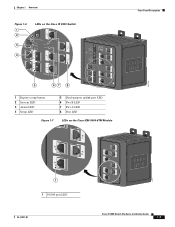
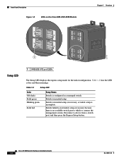
Chapter 1 Overview Figure 1-6 1 2 3 4 LEDs on the Cisco IE 3000 Switch Front-Panel Description 201703 5 67 8 1 Express setup button 2 System LED 3 Alarm LED 4 Setup LED 5 Dual-purpose uplink port LED 6 Pwr B LED 7 Pwr A LED 8 Port LED Figure 1-7 LEDs on the Cisco IEM-3000-8TM Module 201706 1 1 10/100 port LED OL-13017-01 Cisco IE 3000 Switch Hardware Installation Guide 1-7
Chapter 1 Overview Figure 1-6 1 2 3 4 LEDs on the Cisco IE 3000 Switch Front-Panel Description 201703 5 67 8 1 Express setup button 2 System LED 3 Alarm LED 4 Setup LED 5 Dual-purpose uplink port LED 6 Pwr B LED 7 Pwr A LED 8 Port LED Figure 1-7 LEDs on the Cisco IEM-3000-8TM Module 201706 1 1 10/100 port LED OL-13017-01 Cisco IE 3000 Switch Hardware Installation Guide 1-7
Installation Guide
Page 18
...100BASE -FX port LEDs The Setup LED displays the express setup mode for the initial configuration. Switch is in recovery, or initial setup is in initial setup, in initial setup. Cisco IE 3000 Switch Hardware Installation Guide 1-8 OL-13017-01 Table 1-2 Setup LED Color Off (dark) Solid green... Blinking green Solid red Setup Status Switch is no available switch port to which to start initial setup or recovery ...
...100BASE -FX port LEDs The Setup LED displays the express setup mode for the initial configuration. Switch is in recovery, or initial setup is in initial setup, in initial setup. Cisco IE 3000 Switch Hardware Installation Guide 1-8 OL-13017-01 Table 1-2 Setup LED Color Off (dark) Solid green... Blinking green Solid red Setup Status Switch is no available switch port to which to start initial setup or recovery ...

Installation Guide
Page 19
...properly. Table 1-3 System LED Color Off Green Red System Status System is not powered on the circuit, the LED is present on . Red Switch has detected a minor alarm. System is not functioning properly. Alarm LED Table 1-4 lists the alarm LED colors and their meanings. Table 1-5 ... is not present on the circuit, or the system is configured. Power Status LED The switch can operate with the higher voltage. OL-13017-01 Cisco IE 3000 Switch Hardware Installation Guide 1-9 Switch is operating normally. The power status for the failed DC source is off or red, ...
...properly. Table 1-3 System LED Color Off Green Red System Status System is not powered on the circuit, the LED is present on . Red Switch has detected a minor alarm. System is not functioning properly. Alarm LED Table 1-4 lists the alarm LED colors and their meanings. Table 1-5 ... is not present on the circuit, or the system is configured. Power Status LED The switch can operate with the higher voltage. OL-13017-01 Cisco IE 3000 Switch Hardware Installation Guide 1-9 Switch is operating normally. The power status for the failed DC source is off or red, ...

Installation Guide
Page 20
... Color Off Solid green Blinking green Blinking amber Alternating green-amber Solid amber System Status No link. Port is disabled. 1-10 Cisco IE 3000 Switch Hardware Installation Guide OL-13017-01 A link blocked by Spanning Tree Protocol (STP) is sending or receiving data. Alternating green-...shown in Figure 1-6, Figure 1-7, and Figure 1-8. The power status LEDs only show that the power status LEDs do not oscillate at the switch input exceeds the valid level. Port was disabled by management, an address violation, or STP. Blinking green Activity. Table 1-6 10/100...
... Color Off Solid green Blinking green Blinking amber Alternating green-amber Solid amber System Status No link. Port is disabled. 1-10 Cisco IE 3000 Switch Hardware Installation Guide OL-13017-01 A link blocked by Spanning Tree Protocol (STP) is sending or receiving data. Alternating green-...shown in Figure 1-6, Figure 1-7, and Figure 1-8. The power status LEDs only show that the power status LEDs do not oscillate at the switch input exceeds the valid level. Port was disabled by management, an address violation, or STP. Blinking green Activity. Table 1-6 10/100...
Installation Guide
Page 21
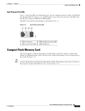
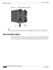
OL-13017-01 Cisco IE 3000 Switch Hardware Installation Guide 1-11 The LED colors have the same meanings as an SFP module, but not both at the same time. The LEDs show how the port is on the bottom of the switch. Note For more information on inserting and removing the compact flash memory... Dual-Purpose Port LEDs Figure 1-9 shows the LEDs on page 2-10. See Figure 1-10. The slot for the compact flash memory card is being used (Ethernet or SFP module). You can configure each port as either a 10/100/1000 port through the RJ-45 connector or as described in -use LED...
OL-13017-01 Cisco IE 3000 Switch Hardware Installation Guide 1-11 The LED colors have the same meanings as an SFP module, but not both at the same time. The LEDs show how the port is on the bottom of the switch. Note For more information on inserting and removing the compact flash memory... Dual-Purpose Port LEDs Figure 1-9 shows the LEDs on page 2-10. See Figure 1-10. The slot for the compact flash memory card is being used (Ethernet or SFP module). You can configure each port as either a 10/100/1000 port through the RJ-45 connector or as described in -use LED...
Installation Guide
Page 22
...latches slide outward to position the switch over a DIN rail and slide inward to secure the switch to a DIN rail. Rear-Panel Description The rear panel of switch Note You can obtain replacement flash memory cards (CF-IE3000=) by calling Cisco Technical Support. Rear-Panel Description Figure... 1-10 Compact Flash Memory Card Slot Chapter 1 Overview 201832 Bottom 1 of the switch, modules, and power converter have ...
...latches slide outward to position the switch over a DIN rail and slide inward to secure the switch to a DIN rail. Rear-Panel Description The rear panel of switch Note You can obtain replacement flash memory cards (CF-IE3000=) by calling Cisco Technical Support. Rear-Panel Description Figure... 1-10 Compact Flash Memory Card Slot Chapter 1 Overview 201832 Bottom 1 of the switch, modules, and power converter have ...