

Installation Guide
Page 4
...the Protective Ground and DC Power 2-13 Grounding the Switch 2-13 Wiring the DC Power Source 2-16 Attach the Power and Relay Connector to the Switch 2-21 Running POST 2-22 Power On the Switch 2-22 Verify POST Results 2-22 Disconnect Power 2-22 Installing the Switch 2-23 Installing the Switch on a DIN ... the Switch to the Power Converter 2-44 Attaching the Power Converter to the Switch 2-45 Installing the Power Converter on a DIN Rail, Wall, or Rack Adapter 2-46 Connecting the DC Power Clip 2-46 Connecting the Power Converter to an AC Power Source 2-47 Cisco IE 3000 Switch Hardware Installation...
...the Protective Ground and DC Power 2-13 Grounding the Switch 2-13 Wiring the DC Power Source 2-16 Attach the Power and Relay Connector to the Switch 2-21 Running POST 2-22 Power On the Switch 2-22 Verify POST Results 2-22 Disconnect Power 2-22 Installing the Switch 2-23 Installing the Switch on a DIN ... the Switch to the Power Converter 2-44 Attaching the Power Converter to the Switch 2-45 Installing the Power Converter on a DIN Rail, Wall, or Rack Adapter 2-46 Connecting the DC Power Clip 2-46 Connecting the Power Converter to an AC Power Source 2-47 Cisco IE 3000 Switch Hardware Installation...

Installation Guide
Page 5
... Cord to the Power Converter 2-48 Connecting the Power Converter to a DC Power Source 2-51 Applying Power to the Power Converter 2-53 Where to Go Next 2-53 Troubleshooting 3-1 Diagnosing Problems 3-1 Verify Switch POST Results 3-1 Verify Switch LEDs 3-2 Verify Switch Connections 3-2 Bad or Damaged Cable 3-2 Ethernet and Fiber Cables 3-2 Link Status 3-3 Transceiver Issues 3-3 Port and Interface...
... Cord to the Power Converter 2-48 Connecting the Power Converter to a DC Power Source 2-51 Applying Power to the Power Converter 2-53 Where to Go Next 2-53 Troubleshooting 3-1 Diagnosing Problems 3-1 Verify Switch POST Results 3-1 Verify Switch LEDs 3-2 Verify Switch Connections 3-2 Bad or Damaged Cable 3-2 Ethernet and Fiber Cables 3-2 Link Status 3-3 Transceiver Issues 3-3 Port and Interface...
Installation Guide
Page 6
...15 Connecting the Protective Ground and DC Power B-16 Grounding the Switch B-17 Wiring the DC Power Source B-19 Attach the Power and Relay Connector to the Switch B-24 Running POST B-25 Power On the Switch B-25 Verify POST Results B-25 Disconnect Power B-25 Installing the Switch B-26 Installing the Switch on a DIN Rail B-27 ... Source B-53 Preparing the AC Power Cord B-53 Connecting the AC Power Cord to the Power Converter B-54 Connecting the Power Converter to a DC Power Source B-57 Applying Power to the Power Converter B-59 Cisco IE 3000 Switch Hardware Installation Guide vi OL-13017-01
...15 Connecting the Protective Ground and DC Power B-16 Grounding the Switch B-17 Wiring the DC Power Source B-19 Attach the Power and Relay Connector to the Switch B-24 Running POST B-25 Power On the Switch B-25 Verify POST Results B-25 Disconnect Power B-25 Installing the Switch B-26 Installing the Switch on a DIN Rail B-27 ... Source B-53 Preparing the AC Power Cord B-53 Connecting the AC Power Cord to the Power Converter B-54 Connecting the Power Converter to a DC Power Source B-57 Applying Power to the Power Converter B-59 Cisco IE 3000 Switch Hardware Installation Guide vi OL-13017-01

Installation Guide
Page 15
... crossover (auto-MDIX) feature. When connecting the switch to workstations, servers, routers, and Cisco IP Phones, be active at a time. These ports use Gigabit Ethernet SFP modules to establish fiber-optic connections to other switches. Power and Relay Connector You connect the DC power and alarm signals to the switch through cable. One connector provides primary...
... crossover (auto-MDIX) feature. When connecting the switch to workstations, servers, routers, and Cisco IP Phones, be active at a time. These ports use Gigabit Ethernet SFP modules to establish fiber-optic connections to other switches. Power and Relay Connector You connect the DC power and alarm signals to the switch through cable. One connector provides primary...

Installation Guide
Page 16
...order a kit (part number ACS-DSBUASYN=) with that adapter from the DC source with both power sources are open , so under power failure conditions, the contacts are operational, the switch draws power from Cisco Systems. For console-port and adapter-pinout information, see the "Two ... relays can be activated for a single switch. LEDs You can be configured to monitor individual switches and switch clusters. All LEDs are labeled A, and you can connect them . Cisco IE 3000 Switch Hardware Installation Guide 1-6 OL-13017-01 The positive DC power connection is labeled V, and the ...
...order a kit (part number ACS-DSBUASYN=) with that adapter from the DC source with both power sources are open , so under power failure conditions, the contacts are operational, the switch draws power from Cisco Systems. For console-port and adapter-pinout information, see the "Two ... relays can be activated for a single switch. LEDs You can be configured to monitor individual switches and switch clusters. All LEDs are labeled A, and you can connect them . Cisco IE 3000 Switch Hardware Installation Guide 1-6 OL-13017-01 The positive DC power connection is labeled V, and the ...

Installation Guide
Page 19
... LED Color System Status Off Alarms are not configured, or the switch is not functioning properly. Each DC input has an associated LED that shows the status of the DC sources fails, the alternate DC source powers the switch, and the corresponding power status LED is either off . otherwise,... system is receiving power and is configured. If alarms are configured. Red Switch has detected a minor alarm. If power is not present; If the one or two DC power sources. OL-13017-01 Cisco IE 3000 Switch Hardware Installation Guide 1-9 Table 1-3 lists the system LED colors and their ...
... LED Color System Status Off Alarms are not configured, or the switch is not functioning properly. Each DC input has an associated LED that shows the status of the DC sources fails, the alternate DC source powers the switch, and the corresponding power status LED is either off . otherwise,... system is receiving power and is configured. If alarms are configured. Red Switch has detected a minor alarm. If power is not present; If the one or two DC power sources. OL-13017-01 Cisco IE 3000 Switch Hardware Installation Guide 1-9 Table 1-3 lists the system LED colors and their ...
Installation Guide
Page 23
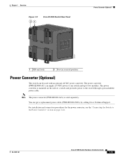
...with an optional AC/DC power converter. Note The power converter (PWR-IE3000-AC=) is mounted on page 2-44. OL-13017-01 Cisco IE 3000 Switch Hardware Installation Guide 1-13 For installation and connection procedures for the power converter, see the "Connecting the Switch to two modules. ...IE3000-AC) can supply 24-VDC power to one switch and up to the Power Converter" section on the side of a switch and provides power to the switch through a preassembled power cable. Chapter 1 Overview Figure 1-11 21 Cisco IE 3000 Switch Rear Panel Power Converter (Optional) 201697 1 DIN ...
...with an optional AC/DC power converter. Note The power converter (PWR-IE3000-AC=) is mounted on page 2-44. OL-13017-01 Cisco IE 3000 Switch Hardware Installation Guide 1-13 For installation and connection procedures for the power converter, see the "Connecting the Switch to two modules. ...IE3000-AC) can supply 24-VDC power to one switch and up to the Power Converter" section on the side of a switch and provides power to the switch through a preassembled power cable. Chapter 1 Overview Figure 1-11 21 Cisco IE 3000 Switch Rear Panel Power Converter (Optional) 201697 1 DIN ...
Installation Guide
Page 24
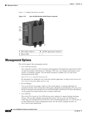
... switches. Figure 1-12 Cisco IE 3000 Switch AC/DC Power Converter 1 2 3 Chapter 1 Overview 202314 1 DC output connector 2 Status LED 3 AC/DC input power connector Management Options The switch supports these management options: • Cisco Network Assistant Cisco Network Assistant is available at no cost and can be downloaded from anywhere in the switch memory, to support desktop-switching features. You can access...
... switches. Figure 1-12 Cisco IE 3000 Switch AC/DC Power Converter 1 2 3 Chapter 1 Overview 202314 1 DC output connector 2 Status LED 3 AC/DC input power connector Management Options The switch supports these management options: • Cisco Network Assistant Cisco Network Assistant is available at no cost and can be downloaded from anywhere in the switch memory, to support desktop-switching features. You can access...
Installation Guide
Page 28
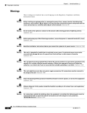
... not work on equipment that power is removed from the DC circuit. Statement 1001 Warning Before performing any of the following ports must be accessed only through an approved network termination unit with integral circuit protection. 10/100/1000 Ethernet Statement 1044 Cisco IE 3000 Switch Hardware Installation Guide 2-2 OL-13017-01 Statement 1017 Warning...
... not work on equipment that power is removed from the DC circuit. Statement 1001 Warning Before performing any of the following ports must be accessed only through an approved network termination unit with integral circuit protection. 10/100/1000 Ethernet Statement 1044 Cisco IE 3000 Switch Hardware Installation Guide 2-2 OL-13017-01 Statement 1017 Warning...
Installation Guide
Page 30
...- The use end-anchors appropriately. When determining where to ports is unrestricted. Access to place the switch, observe these conditions: - Exposed side (not connected to an attached device cannot... rail to the DC power source. • Airflow around the switch and through the vents is sufficient for unrestricted cabling. - Preparing for Installation Chapter 2 Switch Installation • Personnel...in the "Verifying Switch Operation" section on and running POST. Top and bottom: 4.13 in. (105 mm) - Cisco IE 3000 Switch Hardware Installation Guide 2-4 OL-13017-01...
...- The use end-anchors appropriately. When determining where to ports is unrestricted. Access to place the switch, observe these conditions: - Exposed side (not connected to an attached device cannot... rail to the DC power source. • Airflow around the switch and through the vents is sufficient for unrestricted cabling. - Preparing for Installation Chapter 2 Switch Installation • Personnel...in the "Verifying Switch Operation" section on and running POST. Top and bottom: 4.13 in. (105 mm) - Cisco IE 3000 Switch Hardware Installation Guide 2-4 OL-13017-01...
Installation Guide
Page 39
...) wire (such as Belden part number 9912 or equivalent) • For DC power connections, use UL- For instructions on how to connect the power converter to the switch, see the "Connecting the Switch to the Switch, page 2-21 Note The Cisco IE 3000 switch can get replacement power and relay connectors (PWR-IE3000-CNCT=) by using...
...) wire (such as Belden part number 9912 or equivalent) • For DC power connections, use UL- For instructions on how to connect the power converter to the switch, see the "Connecting the Switch to the Switch, page 2-21 Note The Cisco IE 3000 switch can get replacement power and relay connectors (PWR-IE3000-CNCT=) by using...

Installation Guide
Page 42
... power source marked with local and national electrical codes. Statement 1022 Warning This product relies on page 2-44. 2-16 Cisco IE 3000 Switch Hardware Installation Guide OL-13017-01 Statement 1003 Warning Only trained and qualified personnel should be incorporated in this equipment. Ensure...power is removed from 18 to 60 VDC. Warning A readily accessible two-poled disconnect device must connect the switch only to a DC-input power source that has an input supply voltage from the DC circuit. Statement 1005 Warning Installation of the following procedures, ensure that...
... power source marked with local and national electrical codes. Statement 1022 Warning This product relies on page 2-44. 2-16 Cisco IE 3000 Switch Hardware Installation Guide OL-13017-01 Statement 1003 Warning Only trained and qualified personnel should be incorporated in this equipment. Ensure...power is removed from 18 to 60 VDC. Warning A readily accessible two-poled disconnect device must connect the switch only to a DC-input power source that has an input supply voltage from the DC circuit. Statement 1005 Warning Installation of the following procedures, ensure that...
Installation Guide
Page 43
...with insulation should extend from each DC-input power source to a DC-input power source, follow these steps: Step 1 Locate the power and relay connector (see any wire lead. See Figure 2-14. Statement 122 OL-13017-01 Cisco IE 3000 Switch Hardware Installation Guide 2-17 Stripping ...portion of the two twisted pair wires coming from the connector. The positive DC power connection is labeled V, and the return is the adjacent connection labeled RT. Chapter 2 Switch Installation Verifying Switch Operation To wire the switch to 0.25 inch (6.3 mm) ± 0.02 inch (0.5 mm). ...
...with insulation should extend from each DC-input power source to a DC-input power source, follow these steps: Step 1 Locate the power and relay connector (see any wire lead. See Figure 2-14. Statement 122 OL-13017-01 Cisco IE 3000 Switch Hardware Installation Guide 2-17 Stripping ...portion of the two twisted pair wires coming from the connector. The positive DC power connection is labeled V, and the return is the adjacent connection labeled RT. Chapter 2 Switch Installation Verifying Switch Operation To wire the switch to 0.25 inch (6.3 mm) ± 0.02 inch (0.5 mm). ...
Installation Guide
Page 45
...Step 4 through Step 7 using a second power and relay connector. OL-13017-01 Cisco IE 3000 Switch Hardware Installation Guide 2-19 Figure 2-16 shows the completed DC-input wiring on the DC power source. Chapter 2 Switch Installation Verifying Switch Operation Figure 2-15 Torquing the Power and Relay Connector Captive Screws 1 V RT ...the return wire (the one power connection is sufficient. When you are installing the switch and are testing the switch, one connected to RT) to the positive terminal on the DC power source, and connect the other end of the positive wire (the one ...
...Step 4 through Step 7 using a second power and relay connector. OL-13017-01 Cisco IE 3000 Switch Hardware Installation Guide 2-19 Figure 2-16 shows the completed DC-input wiring on the DC power source. Chapter 2 Switch Installation Verifying Switch Operation Figure 2-15 Torquing the Power and Relay Connector Captive Screws 1 V RT ...the return wire (the one power connection is sufficient. When you are installing the switch and are testing the switch, one connected to RT) to the positive terminal on the DC power source, and connect the other end of the positive wire (the one ...
Installation Guide
Page 46
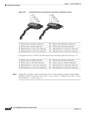
Verifying Switch Operation Chapter 2 Switch Installation Figure 2-16 Completed DC Power Connections on the Power and Relay Connector 1 2 3 4 V RT A A 5 6 7 8 V RT A A 201818 1 Power source A positive connection 2 Power source A return connection 3 External device 1, relay ... 2, relay wire connection Step 8 (Optional) If you plan to connect external alarm devices to the alarm relays and the switch is already installed, go to the "Wiring the External Alarms" section on page 2-11. 2-20 Cisco IE 3000 Switch Hardware Installation Guide OL-13017-01 Otherwise, go to the "Verifying...
Verifying Switch Operation Chapter 2 Switch Installation Figure 2-16 Completed DC Power Connections on the Power and Relay Connector 1 2 3 4 V RT A A 5 6 7 8 V RT A A 201818 1 Power source A positive connection 2 Power source A return connection 3 External device 1, relay ... 2, relay wire connection Step 8 (Optional) If you plan to connect external alarm devices to the alarm relays and the switch is already installed, go to the "Wiring the External Alarms" section on page 2-11. 2-20 Cisco IE 3000 Switch Hardware Installation Guide OL-13017-01 Otherwise, go to the "Verifying...
Installation Guide
Page 48
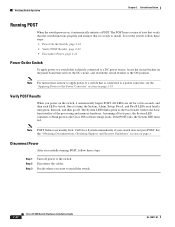
... LED turns red. Disconnect Power After successfully running POST, follow these steps. Decide where you power on the panel board that services the DC circuit, and switch the circuit breaker to the ON position. One at a time, the System, Alarm, Setup, Pwr A, and Pwr B LEDs each ... the Power Converter" section on page x. All LEDs are usually fatal. Call Cisco Systems immediately if your switch does not pass POST. Step 1 Step 2 Step 3 Turn off . To test the switch, follow these steps: • Power On the Switch, page 2-22 • Verify POST Results, page 2-22 • Disconnect...
... LED turns red. Disconnect Power After successfully running POST, follow these steps. Decide where you power on the panel board that services the DC circuit, and switch the circuit breaker to the ON position. One at a time, the System, Alarm, Setup, Pwr A, and Pwr B LEDs each ... the Power Converter" section on page x. All LEDs are usually fatal. Call Cisco Systems immediately if your switch does not pass POST. Step 1 Step 2 Step 3 Turn off . To test the switch, follow these steps: • Power On the Switch, page 2-22 • Verify POST Results, page 2-22 • Disconnect...
Installation Guide
Page 58
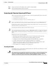
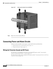
... Alarms, page 2-33 Wiring the Protective Ground and DC Power For instructions on grounding the switch and connecting the DC power, see the "Connecting the Protective Ground and DC Power" section on page 2-44. 2-32 Cisco IE 3000 Switch Hardware Installation Guide OL-13017-01 Connecting Power and ...Alarm Circuits After the switch is installed, you are ready ...
... Alarms, page 2-33 Wiring the Protective Ground and DC Power For instructions on grounding the switch and connecting the DC power, see the "Connecting the Protective Ground and DC Power" section on page 2-44. 2-32 Cisco IE 3000 Switch Hardware Installation Guide OL-13017-01 Connecting Power and ...Alarm Circuits After the switch is installed, you are ready ...

Installation Guide
Page 70
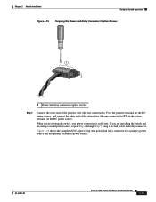
...LED turns amber while the STP discovers the network topology and searches for solutions to the Power Converter The Cisco IE 3000 switch can be a problem with an optional AC/DC power converter (PWR-IE3000-AC). This process takes about 30 seconds, and then the port LED turns ... Connecting the Power Converter to an AC Power Source, page 2-47 • Connecting the Power Converter to a DC Power Source, page 2-51 • Applying Power to a Fiber-Optic SFP Module Port 1 Chapter 2 Switch Installation 202031 1 LC connector Step 3 Step 4 Step 5 Insert the other cable end into a fiber-optic...
...LED turns amber while the STP discovers the network topology and searches for solutions to the Power Converter The Cisco IE 3000 switch can be a problem with an optional AC/DC power converter (PWR-IE3000-AC). This process takes about 30 seconds, and then the port LED turns ... Connecting the Power Converter to an AC Power Source, page 2-47 • Connecting the Power Converter to a DC Power Source, page 2-51 • Applying Power to a Fiber-Optic SFP Module Port 1 Chapter 2 Switch Installation 202031 1 LC connector Step 3 Step 4 Step 5 Insert the other cable end into a fiber-optic...
Installation Guide
Page 72
... top, bottom, or sides of the switch assembly. WARNING Tpeploohewwicseetrurrinccciotosrmrhddois.gchbkTteohfdoairrsveecedosumnecnroevericecthtintehtghareunisnkotitwn.oeof Pwr B (24VDC or 48 VDC) 1 Rtn B 6 Minor Alarm 2 Express Setup System Pwr A Alarm Pwr B 7 Setup 1 3 8 2 4 Cisco Catalyst Installing the Power Converter on a ...A connector, you would a switch module. Connecting the Switch to the Power Converter Chapter 2 Switch Installation Step 3 Step 4 Put the two modules together so that connects DC power from overheating, there must be accessible only by the use the...
... top, bottom, or sides of the switch assembly. WARNING Tpeploohewwicseetrurrinccciotosrmrhddois.gchbkTteohfdoairrsveecedosumnecnroevericecthtintehtghareunisnkotitwn.oeof Pwr B (24VDC or 48 VDC) 1 Rtn B 6 Minor Alarm 2 Express Setup System Pwr A Alarm Pwr B 7 Setup 1 3 8 2 4 Cisco Catalyst Installing the Power Converter on a ...A connector, you would a switch module. Connecting the Switch to the Power Converter Chapter 2 Switch Installation Step 3 Step 4 Put the two modules together so that connects DC power from overheating, there must be accessible only by the use the...
Installation Guide
Page 73
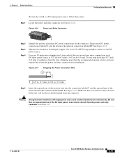
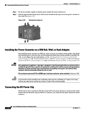
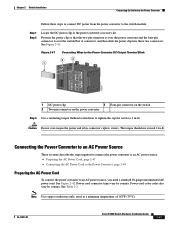
.... See Table 2-2. Note Use copper conductors only, rated at a minimum temperature of 167°F (75°C). OL-13017-01 Cisco IE 3000 Switch Hardware Installation Guide 2-47 Position the power clip so that the two-pin connector is over the power converter and the four-pin...converter to 2 in-lb. Power-cord color codes also vary by country. Step 1 Step 2 Locate the DC power clip in -lb. See Figure 2-41. Chapter 2 Switch Installation Connecting the Switch to the Power Converter Follow these two connectors. Power cord connector types vary by country. See Figure 2-42...
.... See Table 2-2. Note Use copper conductors only, rated at a minimum temperature of 167°F (75°C). OL-13017-01 Cisco IE 3000 Switch Hardware Installation Guide 2-47 Position the power clip so that the two-pin connector is over the power converter and the four-pin...converter to 2 in-lb. Power-cord color codes also vary by country. Step 1 Step 2 Locate the DC power clip in -lb. See Figure 2-41. Chapter 2 Switch Installation Connecting the Switch to the Power Converter Follow these two connectors. Power cord connector types vary by country. See Figure 2-42...