

Installation Guide
Page 3
... OL-13017-01 CONTENTS Preface ix Audience ix Purpose ix Conventions ix Related Publications x Obtaining Documentation, Obtaining Support, and Security Guidelines x Overview 1-1 Overview 1-1 Switch Models 1-2 Front-Panel Description 1-2 10/100 Ports 1-5 Dual-Purpose Ports 1-5 100BASE-FX Ports 1-5 Power and Relay Connector 1-5 Console Port 1-6 LEDs 1-6 ... Card 1-11 Rear-Panel Description 1-12 Power Converter (Optional) 1-13 Management Options 1-14 Network Configurations 1-15 Switch Installation 2-1 Preparing for Installation 2-1 Warnings 2-2 Cisco IE 3000 Switch Hardware Installation Guide iii
... OL-13017-01 CONTENTS Preface ix Audience ix Purpose ix Conventions ix Related Publications x Obtaining Documentation, Obtaining Support, and Security Guidelines x Overview 1-1 Overview 1-1 Switch Models 1-2 Front-Panel Description 1-2 10/100 Ports 1-5 Dual-Purpose Ports 1-5 100BASE-FX Ports 1-5 Power and Relay Connector 1-5 Console Port 1-6 LEDs 1-6 ... Card 1-11 Rear-Panel Description 1-12 Power Converter (Optional) 1-13 Management Options 1-14 Network Configurations 1-15 Switch Installation 2-1 Preparing for Installation 2-1 Warnings 2-2 Cisco IE 3000 Switch Hardware Installation Guide iii

Installation Guide
Page 4
...12 Connecting the Protective Ground and DC Power 2-13 Grounding the Switch 2-13 Wiring the DC Power Source 2-16 Attach the Power and Relay Connector to the Switch 2-21 Running POST 2-22 Power On the Switch... 2-22 Verify POST Results 2-22 Disconnect Power 2-22 Installing the Switch 2-23 Installing the Switch on a DIN Rail 2-23 Installing the Switch on the Wall 2-27 Installing the Switch in a Rack 2-29 Removing the Switch...Ports 2-43 Connecting the Switch to the Power Converter 2-44 Attaching the Power Converter to the Switch 2-45 Installing the Power...
...12 Connecting the Protective Ground and DC Power 2-13 Grounding the Switch 2-13 Wiring the DC Power Source 2-16 Attach the Power and Relay Connector to the Switch 2-21 Running POST 2-22 Power On the Switch... 2-22 Verify POST Results 2-22 Disconnect Power 2-22 Installing the Switch 2-23 Installing the Switch on a DIN Rail 2-23 Installing the Switch on the Wall 2-27 Installing the Switch in a Rack 2-29 Removing the Switch...Ports 2-43 Connecting the Switch to the Power Converter 2-44 Attaching the Power Converter to the Switch 2-45 Installing the Power...
Installation Guide
Page 9
... terminology of data. For information about the standard Cisco IOS Release 12.1 or 12.2 commands, see the switch getting started guide, the switch software configuration guide, the switch command reference, and the switch system message guide on the Cisco.comTechnical Support and Documentation home page. OL-13017-01 Cisco IE 3000 Switch Hardware Installation Guide ix In this manual. We...
... terminology of data. For information about the standard Cisco IOS Release 12.1 or 12.2 commands, see the switch getting started guide, the switch software configuration guide, the switch command reference, and the switch system message guide on the Cisco.comTechnical Support and Documentation home page. OL-13017-01 Cisco IE 3000 Switch Hardware Installation Guide ix In this manual. We...
Installation Guide
Page 11
... Rear-Panel Description, page 1-12 • Power Converter (Optional), page 1-13 • Management Options, page 1-14 • Network Configurations, page 1-15 Overview The Cisco IE 3000 switch provides a rugged and secure switching infrastructure for industrial Ethernet applications, including factory automation, ...describe the Cisco Industrial Ethernet (IE) 3000 switch, hereafter referred to office networking devices like Cisco IP Phones, Cisco Wireless Access Points workstations, and other devices such as the switch. This chapter provides a functional overview of the switches and covers...
... Rear-Panel Description, page 1-12 • Power Converter (Optional), page 1-13 • Management Options, page 1-14 • Network Configurations, page 1-15 Overview The Cisco IE 3000 switch provides a rugged and secure switching infrastructure for industrial Ethernet applications, including factory automation, ...describe the Cisco Industrial Ethernet (IE) 3000 switch, hereafter referred to office networking devices like Cisco IP Phones, Cisco Wireless Access Points workstations, and other devices such as the switch. This chapter provides a functional overview of the switches and covers...
Installation Guide
Page 22
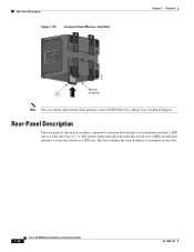
See Figure 1-11. The latches slide outward to position the switch over a DIN rail and slide inward to secure the switch to a DIN rail. The feet stabilize the switch when it is mounted on either a DIN rail or a wall. Rear-Panel Description Figure 1-10 Compact Flash Memory Card... Slot Chapter 1 Overview 201832 Bottom 1 of the switch, modules, and power converter have latches for installation on the wall. 1-12 Cisco IE 3000 Switch Hardware Installation Guide OL-13017-01 Rear-Panel Description The rear panel of switch Note You can obtain replacement flash memory cards (CF-IE3000...
See Figure 1-11. The latches slide outward to position the switch over a DIN rail and slide inward to secure the switch to a DIN rail. The feet stabilize the switch when it is mounted on either a DIN rail or a wall. Rear-Panel Description Figure 1-10 Compact Flash Memory Card... Slot Chapter 1 Overview 201832 Bottom 1 of the switch, modules, and power converter have latches for installation on the wall. 1-12 Cisco IE 3000 Switch Hardware Installation Guide OL-13017-01 Rear-Panel Description The rear panel of switch Note You can obtain replacement flash memory cards (CF-IE3000...
Installation Guide
Page 24
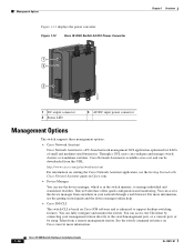
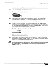
... configuration and monitoring. You can access the CLI either by connecting your network through a web browser. Figure 1-12 Cisco IE 3000 Switch AC/DC Power Converter 1 2 3 Chapter 1 Overview 202314 1 DC output connector 2 Status LED 3 AC/DC input power connector Management Options The switch supports these management options: • Cisco Network Assistant Cisco Network Assistant is enhanced to...
... configuration and monitoring. You can access the CLI either by connecting your network through a web browser. Figure 1-12 Cisco IE 3000 Switch AC/DC Power Converter 1 2 3 Chapter 1 Overview 202314 1 DC output connector 2 Status LED 3 AC/DC input power connector Management Options The switch supports these management options: • Cisco Network Assistant Cisco Network Assistant is enhanced to...
Installation Guide
Page 32
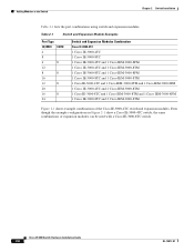
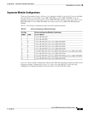
.../100FE 100FX 4 8 4 8 12 8 8 16 12 8 20 16 8 24 Switch and Expansion Modules Combination Cisco IE-3000-4TC 1 Cisco IE-3000-4TC 1 Cisco IE-3000-8TC 1 Cisco IE-3000-4TC and 1 Cisco IEM-3000-8FM 1 Cisco IE-3000-4TC and 1 Cisco IEM-3000-8TM 1 Cisco IE-3000-8TC and 1 Cisco IEM-3000-8FM 1 Cisco IE-3000-8TC and 1 Cisco IEM-3000-8TM 1 Cisco IE-3000-4TC...
.../100FE 100FX 4 8 4 8 12 8 8 16 12 8 20 16 8 24 Switch and Expansion Modules Combination Cisco IE-3000-4TC 1 Cisco IE-3000-4TC 1 Cisco IE-3000-8TC 1 Cisco IE-3000-4TC and 1 Cisco IEM-3000-8FM 1 Cisco IE-3000-4TC and 1 Cisco IEM-3000-8TM 1 Cisco IE-3000-8TC and 1 Cisco IEM-3000-8FM 1 Cisco IE-3000-8TC and 1 Cisco IEM-3000-8TM 1 Cisco IE-3000-4TC...
Installation Guide
Page 34
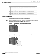
...Switch Chapter 2 Switch Installation 1 Cisco IE-3000-4TC switch with Cisco IEM-3000-8TM and Cisco IEM-3000-8FM expansion modules (12 FE and 8 FX ports) 2 Cisco IE-3000-4TC switch with one Cisco IEM-3000-8FM expansion module (4 FE and 8 FX ports) 3 Cisco IE-3000-4TC switch with one Cisco IEM-3000-8TM expansion modules (12 FE ports) 4 Cisco IE-3000-4TC switch with two Cisco...203759 Cisco IE 3000 Switch Hardware Installation Guide 2-8 OL-13017-01 If necessary, use a screwdriver to the switch: Step 1 Remove the side panel by firmly grasping both sides of the Cisco IE-3000-8TC Switch 201822...
...Switch Chapter 2 Switch Installation 1 Cisco IE-3000-4TC switch with Cisco IEM-3000-8TM and Cisco IEM-3000-8FM expansion modules (12 FE and 8 FX ports) 2 Cisco IE-3000-4TC switch with one Cisco IEM-3000-8FM expansion module (4 FE and 8 FX ports) 3 Cisco IE-3000-4TC switch with one Cisco IEM-3000-8TM expansion modules (12 FE ports) 4 Cisco IE-3000-4TC switch with two Cisco...203759 Cisco IE 3000 Switch Hardware Installation Guide 2-8 OL-13017-01 If necessary, use a screwdriver to the switch: Step 1 Remove the side panel by firmly grasping both sides of the Cisco IE-3000-8TC Switch 201822...
Installation Guide
Page 37
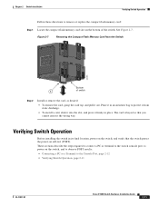
... to observe POST results: • Connecting a PC or a Terminal to the Console Port, page 2-12 • Verifying Switch Operation, page 2-11 OL-13017-01 Cisco IE 3000 Switch Hardware Installation Guide 2-11 Figure 2-7 Removing the Compact Flash Memory Card from static discharge. • To install... a card, slide it into the slot, and press it from the Switch 201851 Bottom 1 of the switch. These sections describe ...
... to observe POST results: • Connecting a PC or a Terminal to the Console Port, page 2-12 • Verifying Switch Operation, page 2-11 OL-13017-01 Cisco IE 3000 Switch Hardware Installation Guide 2-11 Figure 2-7 Removing the Compact Flash Memory Card from static discharge. • To install... a card, slide it into the slot, and press it from the Switch 201851 Bottom 1 of the switch. These sections describe ...
Installation Guide
Page 38
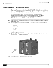
... PC or terminal to the terminal, if needed. 2-12 Cisco IE 3000 Switch Hardware Installation Guide OL-13017-01 See Figure 2-8. (See the "Cable and Adapter Specifications" section on page C-4. To connect a terminal to the console port, you get access to -DB-9 adapter cable. See the switch software configuration guide for pinout descriptions.) Figure 2-8 Connecting...
... PC or terminal to the terminal, if needed. 2-12 Cisco IE 3000 Switch Hardware Installation Guide OL-13017-01 See Figure 2-8. (See the "Cable and Adapter Specifications" section on page C-4. To connect a terminal to the console port, you get access to -DB-9 adapter cable. See the switch software configuration guide for pinout descriptions.) Figure 2-8 Connecting...
Installation Guide
Page 40
...to strip the 10-gauge wire to the wire. 2-14 Cisco IE 3000 Switch Hardware Installation Guide OL-13017-01 See Figure 2-9. Store the ground screw for later use a UL-listed ring terminal lug suitable for number 10-to-12 AWG wire, such as Thomas & Bett part number 10RCR ...or equivalent. Figure 2-9 Stripping the Ground Wire 1 104908 2 3 1 0.5 in. (12.7 mm) ± 0.02 in. ...
...to strip the 10-gauge wire to the wire. 2-14 Cisco IE 3000 Switch Hardware Installation Guide OL-13017-01 See Figure 2-9. Store the ground screw for later use a UL-listed ring terminal lug suitable for number 10-to-12 AWG wire, such as Thomas & Bett part number 10RCR ...or equivalent. Figure 2-9 Stripping the Ground Wire 1 104908 2 3 1 0.5 in. (12.7 mm) ± 0.02 in. ...
Installation Guide
Page 43
...power source to 0.25 inch (6.3 mm) ± 0.02 inch (0.5 mm). Statement 122 OL-13017-01 Cisco IE 3000 Switch Hardware Installation Guide 2-17 See Figure 2-12. Stripping more than the recommended amount of wire can conduct harmful levels of insulation from the power and relay ...connector. Chapter 2 Switch Installation Verifying Switch Operation To wire the switch to the DC power source. Only wire with ...
...power source to 0.25 inch (6.3 mm) ± 0.02 inch (0.5 mm). Statement 122 OL-13017-01 Cisco IE 3000 Switch Hardware Installation Guide 2-17 See Figure 2-12. Stripping more than the recommended amount of wire can conduct harmful levels of insulation from the power and relay ...connector. Chapter 2 Switch Installation Verifying Switch Operation To wire the switch to the DC power source. Only wire with ...
Installation Guide
Page 88
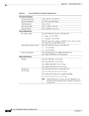
... it can only be connected to 60 VDC • Nominal: 24 or 48 VDC The DC-input power supply is the distance from the rail. Cisco IE 3000 Switch Hardware Installation Guide A-2 OL-13017-01 Height does not include the panel mount brackets. Appendix A Technical Specifications Table... to 185°F (-40 to 85°C) 5 to 95% (noncondensing) 20 g at 11 ms Up to 13,000 ft (3962 m) Up to 40,000 ft (12,192 m) Cisco IE-3000-8TC and Cisco IE-3000-4TC: • Range: 18 to another SELV circuit.
... it can only be connected to 60 VDC • Nominal: 24 or 48 VDC The DC-input power supply is the distance from the rail. Cisco IE 3000 Switch Hardware Installation Guide A-2 OL-13017-01 Height does not include the panel mount brackets. Appendix A Technical Specifications Table... to 185°F (-40 to 85°C) 5 to 95% (noncondensing) 20 g at 11 ms Up to 13,000 ft (3962 m) Up to 40,000 ft (12,192 m) Cisco IE-3000-8TC and Cisco IE-3000-4TC: • Range: 18 to another SELV circuit.
Installation Guide
Page 89
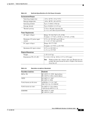
... 165°F (-34 to 74°C) -40 to 185°F (-40 to 85°C) Up to 13,000 ft (3962 m) Up to 40,000 ft (12,192 m) 3.54 in. (90 mm) exposed side 4.13 in. (105 mm) top and bottom Range: 85-264 VAC at 47-63 Hz Nominal: 115 VAC... North American zones InMETRO Standards IEC 60079-15: 2005, third edition IEC 60079-0: 2004, fourth edition EN 60079-15: 2005 EN 60079-0: 2006 ANSI/ISA 12.12.01-2007 CSA C22.2 no. 213-M1987 UL 60079-15, first edition CAN/CSA E 60079-15: 02 IEC 60079-15: 2001 IEC 60079-0: 2000 OL...
... 165°F (-34 to 74°C) -40 to 185°F (-40 to 85°C) Up to 13,000 ft (3962 m) Up to 40,000 ft (12,192 m) 3.54 in. (90 mm) exposed side 4.13 in. (105 mm) top and bottom Range: 85-264 VAC at 47-63 Hz Nominal: 115 VAC... North American zones InMETRO Standards IEC 60079-15: 2005, third edition IEC 60079-0: 2004, fourth edition EN 60079-15: 2005 EN 60079-0: 2006 ANSI/ISA 12.12.01-2007 CSA C22.2 no. 213-M1987 UL 60079-15, first edition CAN/CSA E 60079-15: 02 IEC 60079-15: 2001 IEC 60079-0: 2000 OL...
Installation Guide
Page 99
.../100FE 100FX 4 8 4 8 12 8 8 16 12 8 20 16 8 24 Switch and Expansion Modules Combination Cisco IE-3000-4TC 1 Cisco IE-3000-4TC 1 Cisco IE-3000-8TC 1 Cisco IE-3000-4TC and 1 Cisco IEM-3000-8FM 1 Cisco IE-3000-4TC and 1 Cisco IEM-3000-8TM 1 Cisco IE-3000-8TC and 1 Cisco IEM-3000-8FM 1 Cisco IE-3000-8TC and 1 Cisco IEM-3000-8TM 1 Cisco IE-3000-4TC...
.../100FE 100FX 4 8 4 8 12 8 8 16 12 8 20 16 8 24 Switch and Expansion Modules Combination Cisco IE-3000-4TC 1 Cisco IE-3000-4TC 1 Cisco IE-3000-8TC 1 Cisco IE-3000-4TC and 1 Cisco IEM-3000-8FM 1 Cisco IE-3000-4TC and 1 Cisco IEM-3000-8TM 1 Cisco IE-3000-8TC and 1 Cisco IEM-3000-8FM 1 Cisco IE-3000-8TC and 1 Cisco IEM-3000-8TM 1 Cisco IE-3000-4TC...
Installation Guide
Page 101
... the Switch 1 Cisco IE-3000-4TC switch with Cisco IEM-3000-8TM and Cisco IEM-3000-8FM expansion modules (12 FE and 8 FX ports) 2 Cisco IE-3000-4TC switch with one Cisco IEM-3000-8FM expansion module (4 FE and 8 FX ports) 3 Cisco IE-3000-4TC switch with one Cisco IEM-3000-8TM expansion modules (12 FE ports) 4 Cisco IE-3000-4TC switch with two Cisco IEM...
... the Switch 1 Cisco IE-3000-4TC switch with Cisco IEM-3000-8TM and Cisco IEM-3000-8FM expansion modules (12 FE and 8 FX ports) 2 Cisco IE-3000-4TC switch with one Cisco IEM-3000-8FM expansion module (4 FE and 8 FX ports) 3 Cisco IE-3000-4TC switch with one Cisco IEM-3000-8TM expansion modules (12 FE ports) 4 Cisco IE-3000-4TC switch with two Cisco IEM...
Installation Guide
Page 102
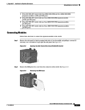
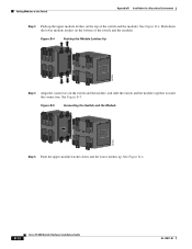
...12 Cisco IE 3000 Switch Hardware Installation Guide OL-13017-01 Push down and the lower latches up the upper module latches (at the bottom of the switch and the module). Figure B-5 Connecting the Switch and the Module 201825 Step 5 Push the upper module latches down the lower module latches (at the top of the switch... and the module). Adding Modules to make the connection. Figure B-4 Pushing the Module Latches Up 201824 Step 4 Align the connectors on the switch and the module, and slide the switch and the module together to the Switch Appendix B ...
...12 Cisco IE 3000 Switch Hardware Installation Guide OL-13017-01 Push down and the lower latches up the upper module latches (at the bottom of the switch and the module). Figure B-5 Connecting the Switch and the Module 201825 Step 5 Push the upper module latches down the lower module latches (at the top of the switch... and the module). Adding Modules to make the connection. Figure B-4 Pushing the Module Latches Up 201824 Step 4 Align the connectors on the switch and the module, and slide the switch and the module together to the Switch Appendix B ...
Installation Guide
Page 107
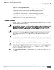
...necessary tools and equipment: • Ratcheting torque flathead screwdriver that the equipment is available. Step 2 Use a wire-stripping tool to 0.5 inch (12.7 mm) ± 0.02 inch (0.5 mm). Ensure that suitable grounding is reliably connected to the external grounding screw. See Figure B-9. and CSA... the ground conductor or operate the equipment in -lb) of a suitably installed ground conductor. OL-13017-01 Cisco IE 3000 Switch Hardware Installation Guide B-17 Contact the appropriate electrical inspection authority or an electrician if you are uncertain that the...
...necessary tools and equipment: • Ratcheting torque flathead screwdriver that the equipment is available. Step 2 Use a wire-stripping tool to 0.5 inch (12.7 mm) ± 0.02 inch (0.5 mm). Ensure that suitable grounding is reliably connected to the external grounding screw. See Figure B-9. and CSA... the ground conductor or operate the equipment in -lb) of a suitably installed ground conductor. OL-13017-01 Cisco IE 3000 Switch Hardware Installation Guide B-17 Contact the appropriate electrical inspection authority or an electrician if you are uncertain that the...
Installation Guide
Page 108
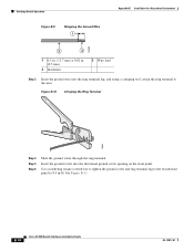
...104908 2 3 1 0.5 in. (12.7 mm) ± 0.02 in -lb. Figure B-10 Crimping the Ring Terminal 76666 Step 4 Step 5 Step 6 Slide the ground screw through the ring terminal. Use a ratcheting torque screwdriver to tighten the ground screw and ring terminal lug to the switch front panel to 8.5 in . (0.5... Wire lead Step 3 Insert the ground wire into the functional ground screw opening on the front panel. See Figure B-11. B-18 Cisco IE 3000 Switch Hardware Installation Guide OL-13017-01 Insert the ground screw into the ring terminal lug, and using a crimping tool, crimp the ring ...
...104908 2 3 1 0.5 in. (12.7 mm) ± 0.02 in -lb. Figure B-10 Crimping the Ring Terminal 76666 Step 4 Step 5 Step 6 Slide the ground screw through the ring terminal. Use a ratcheting torque screwdriver to tighten the ground screw and ring terminal lug to the switch front panel to 8.5 in . (0.5... Wire lead Step 3 Insert the ground wire into the functional ground screw opening on the front panel. See Figure B-11. B-18 Cisco IE 3000 Switch Hardware Installation Guide OL-13017-01 Insert the ground screw into the ring terminal lug, and using a crimping tool, crimp the ring ...
Installation Guide
Page 110
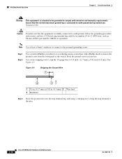
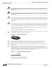
Figure B-12 Power and Relay Connector V RT A A 201815 Step 2 Step 3 Step 4 Identify the positive and return DC power connections on page B-49. The positive DC power connection is labeled V, and the return is not in . (0.5 mm) B-20 Cisco IE 3000 Switch Hardware Installation Guide OL-13017-... the power and relay connector (see Figure B-12). Do not strip more than 0.27 inch (6.8 mm) of insulation from the wire. To wire the switch to a DC-input power source that power is removed from the DC circuit. Verifying Switch Operation Appendix B Installation In a Hazardous Environment ...
Figure B-12 Power and Relay Connector V RT A A 201815 Step 2 Step 3 Step 4 Identify the positive and return DC power connections on page B-49. The positive DC power connection is labeled V, and the return is not in . (0.5 mm) B-20 Cisco IE 3000 Switch Hardware Installation Guide OL-13017-... the power and relay connector (see Figure B-12). Do not strip more than 0.27 inch (6.8 mm) of insulation from the wire. To wire the switch to a DC-input power source that power is removed from the DC circuit. Verifying Switch Operation Appendix B Installation In a Hazardous Environment ...