

Installation Guide
Page 15
...either a 10/100/1000 port or as fixed 10, 100, or 1000 Mb/s (Gigabit) Ethernet ports and can configure the duplex setting. (See the switch software configuration for more information about these ports for speed and duplex autonegotiation in the command-line ...supply B) provides secondary power and the minor alarm signal. You can use the mdix auto interface configuration command in compliance with LC connectors to connect to a fiber-optic SFP module. Power and Relay Connector You connect the DC power and alarm signals to the switch through cable. OL-13017-01 Cisco IE 3000 Switch...
...either a 10/100/1000 port or as fixed 10, 100, or 1000 Mb/s (Gigabit) Ethernet ports and can configure the duplex setting. (See the switch software configuration for more information about these ports for speed and duplex autonegotiation in the command-line ...supply B) provides secondary power and the minor alarm signal. You can use the mdix auto interface configuration command in compliance with LC connectors to connect to a fiber-optic SFP module. Power and Relay Connector You connect the DC power and alarm signals to the switch through cable. OL-13017-01 Cisco IE 3000 Switch...

Installation Guide
Page 16
... configuration guide for environmental, power supply, and port status alarm conditions and can associate any alarm condition with one of the two power sources fail, the other continues to -DB-9 adapter cable. Console Port You can operate with a single power source or with both power sources are operational, the switch draws power from Cisco Systems. For console-port...
... configuration guide for environmental, power supply, and port status alarm conditions and can associate any alarm condition with one of the two power sources fail, the other continues to -DB-9 adapter cable. Console Port You can operate with a single power source or with both power sources are operational, the switch draws power from Cisco Systems. For console-port...

Installation Guide
Page 19
... 1-5 lists the power status LED colors and meanings. OL-13017-01 Cisco IE 3000 Switch Hardware Installation Guide 1-9 Power Status LED The switch can operate with the higher voltage. If the switch has dual power sources, the switch draws power from the power source with one ...of the corresponding DC input. Power is off or red, depending on the alarm configuration. Switch is operating normally. If power is not present, the LED color depends on the associated circuit, and the power supply...
... 1-5 lists the power status LED colors and meanings. OL-13017-01 Cisco IE 3000 Switch Hardware Installation Guide 1-9 Power Status LED The switch can operate with the higher voltage. If the switch has dual power sources, the switch draws power from the power source with one ...of the corresponding DC input. Power is off or red, depending on the alarm configuration. Switch is operating normally. If power is not present, the LED color depends on the associated circuit, and the power supply...
Installation Guide
Page 23
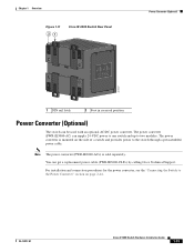
... Support. OL-13017-01 Cisco IE 3000 Switch Hardware Installation Guide 1-13 You can be used with an optional AC/DC power converter. The power converter (PWR-IE3000-AC) can supply 24-VDC power to one switch and up to the Power Converter" section on the side of a switch and provides power to the switch through a preassembled power cable. For installation and...
... Support. OL-13017-01 Cisco IE 3000 Switch Hardware Installation Guide 1-13 You can be used with an optional AC/DC power converter. The power converter (PWR-IE3000-AC) can supply 24-VDC power to one switch and up to the Power Converter" section on the side of a switch and provides power to the switch through a preassembled power cable. For installation and...
Installation Guide
Page 28
... in the absence of lightning activity. All connections must be accessed only through an approved network termination unit with integral circuit protection. 10/100/1000 Ethernet Statement 1044 Cisco IE 3000 Switch Hardware Installation Guide 2-2 OL-13017-01 Statement 1004 Warning This...disconnect cables during periods of a suitably installed ground conductor. Statement 1024 Warning This unit might have more than one power supply connection. Contact the appropriate electrical inspection authority or an electrician if you connect the system to all national laws and...
... in the absence of lightning activity. All connections must be accessed only through an approved network termination unit with integral circuit protection. 10/100/1000 Ethernet Statement 1044 Cisco IE 3000 Switch Hardware Installation Guide 2-2 OL-13017-01 Statement 1004 Warning This...disconnect cables during periods of a suitably installed ground conductor. Statement 1024 Warning This unit might have more than one power supply connection. Contact the appropriate electrical inspection authority or an electrician if you connect the system to all national laws and...

Installation Guide
Page 42
.... Warning A readily accessible two-poled disconnect device must connect the switch only to a DC-input power source that the protective device is rated not greater than: 5A. Statement 1022 Warning This product relies on page 2-44. 2-16 Cisco IE 3000 Switch Hardware Installation Guide OL-13017-01 Ensure that has an input supply voltage from 18...
.... Warning A readily accessible two-poled disconnect device must connect the switch only to a DC-input power source that the protective device is rated not greater than: 5A. Statement 1022 Warning This product relies on page 2-44. 2-16 Cisco IE 3000 Switch Hardware Installation Guide OL-13017-01 Ensure that has an input supply voltage from 18...
Installation Guide
Page 61
... Cisco IE 3000 Switch Hardware Installation Guide 2-35 Chapter 2 Switch Installation Connecting Power and Alarm Circuits Figure 2-30 shows the completed wiring for instructions on page 2-21 for two power supplies and two external alarm devices. Figure 2-30 Completed Connections for Two External Alarm Devices on the Power and Relay Connector 1 2 3 4 V RT A A 5 6 7 8 V RT A A 201820 1 Power source A positive connection 5 Power...
... Cisco IE 3000 Switch Hardware Installation Guide 2-35 Chapter 2 Switch Installation Connecting Power and Alarm Circuits Figure 2-30 shows the completed wiring for instructions on page 2-21 for two power supplies and two external alarm devices. Figure 2-30 Completed Connections for Two External Alarm Devices on the Power and Relay Connector 1 2 3 4 V RT A A 5 6 7 8 V RT A A 201820 1 Power source A positive connection 5 Power...
Installation Guide
Page 72
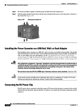
...power from accessibility to the Switch" section on page 2-45, the "Installing the Switch on a DIN Rail" section on page 2-23, the "Installing the Switch on the Wall" section on page 2-27, or the "Installing the Switch in the switch recess. Connecting the DC Power Clip The DC power clip is supplied...Put the two modules together so that connector. 2-46 Cisco IE 3000 Switch Hardware Installation Guide OL-13017-01 You should first attach the power converter to the switch module. See Figure 2-40. Connecting the Switch to the switch. Figure 2-40 Pushing the Latches In CONSOLE 202297 ...
...power from accessibility to the Switch" section on page 2-45, the "Installing the Switch on a DIN Rail" section on page 2-23, the "Installing the Switch on the Wall" section on page 2-27, or the "Installing the Switch in the switch recess. Connecting the DC Power Clip The DC power clip is supplied...Put the two modules together so that connector. 2-46 Cisco IE 3000 Switch Hardware Installation Guide OL-13017-01 You should first attach the power converter to the switch module. See Figure 2-40. Connecting the Switch to the switch. Figure 2-40 Pushing the Latches In CONSOLE 202297 ...
Installation Guide
Page 77
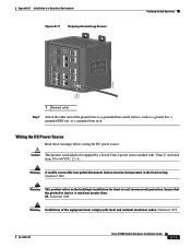
...ground wire connection on the country that the switch requires. Warning Use twisted-pair supply wires suitable for 86°F (30°C) above surrounding ambient temperature outside the enclosure. Insert the other end of wire can also connect the power converter to earth ground, use 18-AWG...-AWG stranded copper wire, such as Belden part number 9912 or the equivalent. For DC connections from the power converter to a DC power source. OL-13017-01 Cisco IE 3000 Switch Hardware Installation Guide 2-51 Using a 18-gauge wire-stripping tool, strip the ground wire and both ends ...
...ground wire connection on the country that the switch requires. Warning Use twisted-pair supply wires suitable for 86°F (30°C) above surrounding ambient temperature outside the enclosure. Insert the other end of wire can also connect the power converter to earth ground, use 18-AWG...-AWG stranded copper wire, such as Belden part number 9912 or the equivalent. For DC connections from the power converter to a DC power source. OL-13017-01 Cisco IE 3000 Switch Hardware Installation Guide 2-51 Using a 18-gauge wire-stripping tool, strip the ground wire and both ends ...
Installation Guide
Page 88
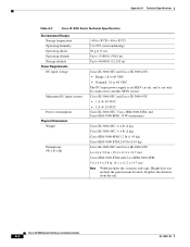
...Cisco IE 3000 Switch Hardware Installation Guide A-2 OL-13017-01 Depth is an SELV circuit, and it can only be connected to another SELV circuit. Cisco IE-3000-8TC and Cisco IE-3000-4TC • 1 A @ 48 VDC • 2 A @ 24 VDC Cisco IE-3000-8TC, Cisco IEM-3000-8TM. Appendix A Technical Specifications Table A-2 Cisco...The DC-input power supply is the distance from the rail. and Cisco IEM-3000-8FM: 35 W (maximum) Cisco IE-3000-8TC: 4.4 lb (2 kg) Cisco IE-3000-4TC: 4.4 lb (2 kg) Cisco IEM-3000-8FM 3.2 lb (1.45 kg) Cisco IEM-3000-8TM 2.05 lb (0.93 kg) Cisco IE-3000-8TC and Cisco IE-3000-4TC...
...Cisco IE 3000 Switch Hardware Installation Guide A-2 OL-13017-01 Depth is an SELV circuit, and it can only be connected to another SELV circuit. Cisco IE-3000-8TC and Cisco IE-3000-4TC • 1 A @ 48 VDC • 2 A @ 24 VDC Cisco IE-3000-8TC, Cisco IEM-3000-8TM. Appendix A Technical Specifications Table A-2 Cisco...The DC-input power supply is the distance from the rail. and Cisco IEM-3000-8FM: 35 W (maximum) Cisco IE-3000-8TC: 4.4 lb (2 kg) Cisco IE-3000-4TC: 4.4 lb (2 kg) Cisco IEM-3000-8FM 3.2 lb (1.45 kg) Cisco IEM-3000-8TM 2.05 lb (0.93 kg) Cisco IE-3000-8TC and Cisco IE-3000-4TC...

Installation Guide
Page 92
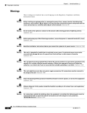
...Ethernet Statement 1044 Cisco IE 3000 Switch Hardware Installation Guide B-2 OL-13017-01 Warning Before working on the system or connect or disconnect cables during periods of lightning activity. Never defeat the ground conductor or operate the equipment in restricted access areas. Statement 43 Warning Do not work on equipment that power... of a suitably installed ground conductor. Metal objects will heat up when connected to power and ground and can be allowed to its power source. Statement 1024 Warning This unit might have more than one power supply connection.
...Ethernet Statement 1044 Cisco IE 3000 Switch Hardware Installation Guide B-2 OL-13017-01 Warning Before working on the system or connect or disconnect cables during periods of lightning activity. Never defeat the ground conductor or operate the equipment in restricted access areas. Statement 43 Warning Do not work on equipment that power... of a suitably installed ground conductor. Metal objects will heat up when connected to power and ground and can be allowed to its power source. Statement 1024 Warning This unit might have more than one power supply connection.
Installation Guide
Page 93
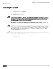
... will be accessible only by the use of a tool. To verify switch operation, perform POST on or verify that the area is removed from the vicinity of the switch. Statement 1067 OL-13017-01 Cisco IE 3000 Switch Hardware Installation Guide B-3 Be sure that power is nonhazardous before...To prevent airflow restriction, allow clearance around the ventilation openings to ensure that power is removed or the area is supplied as "open type" equipment. This could be accidentally turned on the switch in a nonhazardous location before proceeding. The interior of the enclosure must meet ...
... will be accessible only by the use of a tool. To verify switch operation, perform POST on or verify that the area is removed from the vicinity of the switch. Statement 1067 OL-13017-01 Cisco IE 3000 Switch Hardware Installation Guide B-3 Be sure that power is nonhazardous before...To prevent airflow restriction, allow clearance around the ventilation openings to ensure that power is removed or the area is supplied as "open type" equipment. This could be accidentally turned on the switch in a nonhazardous location before proceeding. The interior of the enclosure must meet ...

Installation Guide
Page 95
...par les autorités locales qualifiées au moment de l'installation. In addition, if equipment is supplied with respect to be one of ETS 300 253 or CCITT K27. • AC-power distribution shall be installed in Class I Division 2 Groupes A, B, C, D dangereux et non dangereux. ...indicating the hazardous location temperature code. Les combinaisons d'équipements dans le système . OL-13017-01 Cisco IE 3000 Switch Hardware Installation Guide B-5 EMC Environmental Conditions for Products Installed in a domestic environment, interference could occur.
...par les autorités locales qualifiées au moment de l'installation. In addition, if equipment is supplied with respect to be one of ETS 300 253 or CCITT K27. • AC-power distribution shall be installed in Class I Division 2 Groupes A, B, C, D dangereux et non dangereux. ...indicating the hazardous location temperature code. Les combinaisons d'équipements dans le système . OL-13017-01 Cisco IE 3000 Switch Hardware Installation Guide B-5 EMC Environmental Conditions for Products Installed in a domestic environment, interference could occur.
Installation Guide
Page 96
...switch. The use end-anchors appropriately. When determining where to the switch. North American Hazardous Location Approval Appendix B Installation In a Hazardous Environment • This equipment is supplied...switch is required whenever you handle Cisco equipment. Cisco IE 3000 Switch Hardware Installation Guide B-6 OL-13017-01 Installation and maintenance personnel should be trained in the apparatus or external to the apparatus, to prevent the rated voltage from accessibility...personal injury resulting from being exceeded by powering it on component boards. The enclosure ...
...switch. The use end-anchors appropriately. When determining where to the switch. North American Hazardous Location Approval Appendix B Installation In a Hazardous Environment • This equipment is supplied...switch is required whenever you handle Cisco equipment. Cisco IE 3000 Switch Hardware Installation Guide B-6 OL-13017-01 Installation and maintenance personnel should be trained in the apparatus or external to the apparatus, to prevent the rated voltage from accessibility...personal injury resulting from being exceeded by powering it on component boards. The enclosure ...
Installation Guide
Page 105
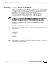
...supplied RJ-45-to -DB-25 female DTE adapter. For console-port and adapter-pinout information, see the "Cable and Adapter Specifications" section on page C-4 for instructions. Be sure that power is removed or the area is configured to the switch or any device on the switch... power applied to communicate with the switch using hardware flow control. To connect a terminal to the switch: Step 1 Step 2 Step 3 Make sure that adapter from Cisco...bits • One stop bit • No parity After you get access to the switch, you need to provide an RJ-45-to -DB-9 adapter cable. ...
...supplied RJ-45-to -DB-25 female DTE adapter. For console-port and adapter-pinout information, see the "Cable and Adapter Specifications" section on page C-4 for instructions. Be sure that power is removed or the area is configured to the switch or any device on the switch... power applied to communicate with the switch using hardware flow control. To connect a terminal to the switch: Step 1 Step 2 Step 3 Make sure that adapter from Cisco...bits • One stop bit • No parity After you get access to the switch, you need to provide an RJ-45-to -DB-9 adapter cable. ...
Installation Guide
Page 109
Warning A readily accessible two-poled disconnect device must comply with "Class 2" and rated ...Hazardous Environment Figure B-11 Torquing Ground-Lug Screws Verifying Switch Operation 201696 1 1 Ground cable Step 7 Attach the other end of the equipment must be supplied by a Listed Class 2 power source marked with local and national electrical codes. Statement.... Wiring the DC Power Source Read these warnings before wiring the DC power source: Caution This product is rated not greater than: 5A. Statement 1074 OL-13017-01 Cisco IE 3000 Switch Hardware Installation Guide B-19...
Warning A readily accessible two-poled disconnect device must comply with "Class 2" and rated ...Hazardous Environment Figure B-11 Torquing Ground-Lug Screws Verifying Switch Operation 201696 1 1 Ground cable Step 7 Attach the other end of the equipment must be supplied by a Listed Class 2 power source marked with local and national electrical codes. Statement.... Wiring the DC Power Source Read these warnings before wiring the DC power source: Caution This product is rated not greater than: 5A. Statement 1074 OL-13017-01 Cisco IE 3000 Switch Hardware Installation Guide B-19...
Installation Guide
Page 110
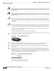
... (such as Belden part number 9318). To wire the switch to the DC power source. Caution For wire connections to the power and relay connector, you must connect the switch only to 60 VDC. To wire the switch to the optional AC/DC converter, go to the ... B-12. Verifying Switch Operation Appendix B Installation In a Hazardous Environment Warning Before performing any of the following procedures, ensure that has an input supply voltage from the power and relay connector after installation. If the supply voltage is not in . (0.5 mm) B-20 Cisco IE 3000 Switch Hardware Installation Guide ...
... (such as Belden part number 9318). To wire the switch to the DC power source. Caution For wire connections to the power and relay connector, you must connect the switch only to 60 VDC. To wire the switch to the optional AC/DC converter, go to the ... B-12. Verifying Switch Operation Appendix B Installation In a Hazardous Environment Warning Before performing any of the following procedures, ensure that has an input supply voltage from the power and relay connector after installation. If the supply voltage is not in . (0.5 mm) B-20 Cisco IE 3000 Switch Hardware Installation Guide ...
Installation Guide
Page 116
... be accessible only by the use of the enclosure must meet IP 54 or NEMA type 4 minimum enclosure rating standards. Statement 1063 Warning When used in a Class I , Division 2 installations. Top and bottom: 4.13 in . (65 mm) B-26 Cisco IE 3000 Switch Hardware ...Switch in a Rack Warning This equipment is suitably designed for all power, input and output wiring, that complies with the governing electrical codes and in accordance with the authority having jurisdiction over Class I , Division 2, hazardous location, this equipment must be mounted within an enclosure that is supplied...
... be accessible only by the use of the enclosure must meet IP 54 or NEMA type 4 minimum enclosure rating standards. Statement 1063 Warning When used in a Class I , Division 2 installations. Top and bottom: 4.13 in . (65 mm) B-26 Cisco IE 3000 Switch Hardware ...Switch in a Rack Warning This equipment is suitably designed for all power, input and output wiring, that complies with the governing electrical codes and in accordance with the authority having jurisdiction over Class I , Division 2, hazardous location, this equipment must be mounted within an enclosure that is supplied...
Installation Guide
Page 130
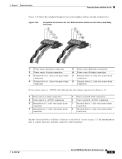
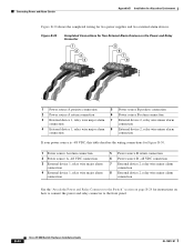
B-40 Cisco IE 3000 Switch Hardware Installation Guide OL-13017-01 Connecting Power and Alarm Circuits Appendix B Installation In a Hazardous Environment Figure B-30 shows the completed wiring for instructions on page B-24 for two power supplies and two external alarm devices. Figure B-30 Completed Connections for Two External Alarm Devices on the Power and Relay Connector 1 2 3 4 V RT...
B-40 Cisco IE 3000 Switch Hardware Installation Guide OL-13017-01 Connecting Power and Alarm Circuits Appendix B Installation In a Hazardous Environment Figure B-30 shows the completed wiring for instructions on page B-24 for two power supplies and two external alarm devices. Figure B-30 Completed Connections for Two External Alarm Devices on the Power and Relay Connector 1 2 3 4 V RT...
Installation Guide
Page 142
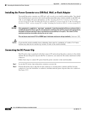
... must be accessible only by the use the alarm connections on page B-33. For more information, see the "Attaching the Power Converter to the switch and then install the entire switch assembly on the DIN rail, wall, or rack adapter. Warning This equipment is over the power converter and the four-pin connector is supplied as...
... must be accessible only by the use the alarm connections on page B-33. For more information, see the "Attaching the Power Converter to the switch and then install the entire switch assembly on the DIN rail, wall, or rack adapter. Warning This equipment is over the power converter and the four-pin connector is supplied as...

