

Installation Guide
Page 15
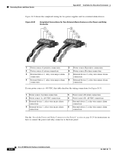
...or half-duplex mode. Only one port can use Gigabit Ethernet SFP modules to establish fiber-optic connections to the switch through cable. You can configure them as an SFP ...connector provides primary DC power (supply A) and the major alarm signal, and a second connector (supply B) provides secondary power and the minor alarm signal. You can set for your switch software. 100BASE-FX...mdix auto interface configuration command in an SFP module slot. OL-13017-01 Cisco IE 3000 Switch Hardware Installation Guide 1-5 The two connectors are physically identical and are field-replaceable...
...or half-duplex mode. Only one port can use Gigabit Ethernet SFP modules to establish fiber-optic connections to the switch through cable. You can configure them as an SFP ...connector provides primary DC power (supply A) and the major alarm signal, and a second connector (supply B) provides secondary power and the minor alarm signal. You can set for your switch software. 100BASE-FX...mdix auto interface configuration command in an SFP module slot. OL-13017-01 Cisco IE 3000 Switch Hardware Installation Guide 1-5 The two connectors are physically identical and are field-replaceable...

Installation Guide
Page 16
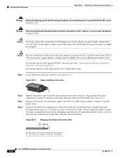
... to a PC through the GUI management applications-the Cisco Network Assistant application for multiple switches and the device manager GUI for instructions on the power and relay connector are operational, the switch draws power from Cisco Systems. For console-port and adapter-pinout information,...under power failure conditions, the contacts are visible through the console port and the supplied RJ-45-to -DB-25 female DTE adapter. Figure 1-5 Power and Relay Connector V RT A A 201815 The switch can get replacement power and relay connectors (PWR-IE3000-CNCT=) by calling Cisco Technical...
... to a PC through the GUI management applications-the Cisco Network Assistant application for multiple switches and the device manager GUI for instructions on the power and relay connector are operational, the switch draws power from Cisco Systems. For console-port and adapter-pinout information,...under power failure conditions, the contacts are visible through the console port and the supplied RJ-45-to -DB-25 female DTE adapter. Figure 1-5 Power and Relay Connector V RT A A 201815 The switch can get replacement power and relay connectors (PWR-IE3000-CNCT=) by calling Cisco Technical...

Installation Guide
Page 19
... LED that shows the status of the DC sources fails, the alternate DC source powers the switch, and the corresponding power status LED is present on . OL-13017-01 Cisco IE 3000 Switch Hardware Installation Guide 1-9 Chapter 1 Overview Front-Panel Description System LED The System LED...not configured, or the switch is configured. Blinking red Switch has detected a major alarm. If power is present on the associated circuit, and the power supply alarm is off . If alarms are configured. If the switch has dual power sources, the switch draws power from the power source with one of the...
... LED that shows the status of the DC sources fails, the alternate DC source powers the switch, and the corresponding power status LED is present on . OL-13017-01 Cisco IE 3000 Switch Hardware Installation Guide 1-9 Chapter 1 Overview Front-Panel Description System LED The System LED...not configured, or the switch is configured. Blinking red Switch has detected a major alarm. If power is present on the associated circuit, and the power supply alarm is off . If alarms are configured. If the switch has dual power sources, the switch draws power from the power source with one of the...
Installation Guide
Page 23
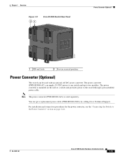
... supply 24-VDC power to one switch and up to the Power Converter" section on the side of a switch and provides power to the switch through a preassembled power cable. For installation and connection procedures for the power converter, see the "Connecting the Switch to two modules. Note The power converter (PWR-IE3000-AC=) is mounted on page 2-44. OL-13017-01 Cisco...
... supply 24-VDC power to one switch and up to the Power Converter" section on the side of a switch and provides power to the switch through a preassembled power cable. For installation and connection procedures for the power converter, see the "Connecting the Switch to two modules. Note The power converter (PWR-IE3000-AC=) is mounted on page 2-44. OL-13017-01 Cisco...
Installation Guide
Page 28
...integral circuit protection. 10/100/1000 Ethernet Statement 1044 Cisco IE 3000 Switch Hardware Installation Guide 2-2 OL-13017-01 Preparing for installation in restricted access areas. All connections must be allowed to de-energize the unit. Metal objects will heat up when connected to power and ground and can be handled ... operate the equipment in the Regulatory Compliance and Safety Information Guide. Statement 1024 Warning This unit might have more than one power supply connection. Statement 43 Warning Do not work on equipment that suitable grounding is connected to its...
...integral circuit protection. 10/100/1000 Ethernet Statement 1044 Cisco IE 3000 Switch Hardware Installation Guide 2-2 OL-13017-01 Preparing for installation in restricted access areas. All connections must be allowed to de-energize the unit. Metal objects will heat up when connected to power and ground and can be handled ... operate the equipment in the Regulatory Compliance and Safety Information Guide. Statement 1024 Warning This unit might have more than one power supply connection. Statement 43 Warning Do not work on equipment that suitable grounding is connected to its...

Installation Guide
Page 42
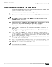
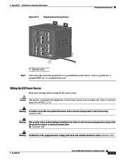
... 2-44. 2-16 Cisco IE 3000 Switch Hardware Installation Guide OL-13017-01 Statement 1003 Warning Only trained and qualified personnel should be allowed to install, replace, or service this range, the switch might not operate properly...Switch Operation Chapter 2 Switch Installation Wiring the DC Power Source Read these warnings before wiring the DC power source: Caution This product is intended to be supplied by a Listed Class 2 power source marked with local and national electrical codes. Ensure that has an input supply voltage from 18 to 60 VDC, 2.1 A. Warning A readily accessible...
... 2-44. 2-16 Cisco IE 3000 Switch Hardware Installation Guide OL-13017-01 Statement 1003 Warning Only trained and qualified personnel should be allowed to install, replace, or service this range, the switch might not operate properly...Switch Operation Chapter 2 Switch Installation Wiring the DC Power Source Read these warnings before wiring the DC power source: Caution This product is intended to be supplied by a Listed Class 2 power source marked with local and national electrical codes. Ensure that has an input supply voltage from 18 to 60 VDC, 2.1 A. Warning A readily accessible...
Installation Guide
Page 61
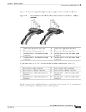
... Relay Connector to the Switch" section on how to connect the power and relay connector to the front panel. Chapter 2 Switch Installation Connecting Power and Alarm Circuits Figure 2-30 shows the completed wiring for instructions on page 2-21 for two power supplies and two external alarm devices. OL-13017-01 Cisco IE 3000 Switch Hardware Installation Guide 2-35...
... Relay Connector to the Switch" section on how to connect the power and relay connector to the front panel. Chapter 2 Switch Installation Connecting Power and Alarm Circuits Figure 2-30 shows the completed wiring for instructions on page 2-21 for two power supplies and two external alarm devices. OL-13017-01 Cisco IE 3000 Switch Hardware Installation Guide 2-35...
Installation Guide
Page 72
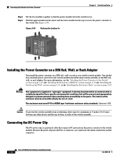
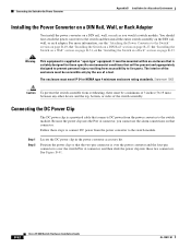
...supplied as you cannot use of the enclosure must be present and appropriately designed to prevent personal injury resulting from accessibility to the switch. You should first attach the power converter to the Switch" section on page 2-45, the "Installing the Switch...System Pwr A Alarm Pwr B 7 Setup 1 3 8 2 4 Cisco Catalyst Installing the Power Converter on a DIN Rail, Wall, or Rack Adapter You install the power converter on page 2-29. Connecting the Switch to the Power Converter Chapter 2 Switch Installation Step 3 Step 4 Put the two modules together so that connector...
...supplied as you cannot use of the enclosure must be present and appropriately designed to prevent personal injury resulting from accessibility to the switch. You should first attach the power converter to the Switch" section on page 2-45, the "Installing the Switch...System Pwr A Alarm Pwr B 7 Setup 1 3 8 2 4 Cisco Catalyst Installing the Power Converter on a DIN Rail, Wall, or Rack Adapter You install the power converter on page 2-29. Connecting the Switch to the Power Converter Chapter 2 Switch Installation Step 3 Step 4 Put the two modules together so that connector...
Installation Guide
Page 77
...-pair supply wires suitable for 86°F (30°C) above surrounding ambient temperature outside the enclosure. Statement 1067 Step 1 Step 2 Step 3 Step 4 Step 5 Step 6 Measure a single length of the twisted pair wires to 0.25 inch (6.3 mm) ± 0.02 inch (0.5 mm). For connections from the power converter ...2-9. Tighten the earth-ground wire connection terminal block screw. OL-13017-01 Cisco IE 3000 Switch Hardware Installation Guide 2-51 Do not strip more than 0.27 inch (6.8 mm) of wire can also connect the power converter to the 24 VDC that you are using it in -lb. Note...
...-pair supply wires suitable for 86°F (30°C) above surrounding ambient temperature outside the enclosure. Statement 1067 Step 1 Step 2 Step 3 Step 4 Step 5 Step 6 Measure a single length of the twisted pair wires to 0.25 inch (6.3 mm) ± 0.02 inch (0.5 mm). For connections from the power converter ...2-9. Tighten the earth-ground wire connection terminal block screw. OL-13017-01 Cisco IE 3000 Switch Hardware Installation Guide 2-51 Do not strip more than 0.27 inch (6.8 mm) of wire can also connect the power converter to the 24 VDC that you are using it in -lb. Note...
Installation Guide
Page 88
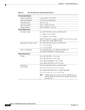
...the panel mount brackets. Cisco IE 3000 Switch Hardware Installation Guide A-2 OL-13017-01 Depth is an SELV circuit, and it can only be connected to another SELV circuit. Cisco IE-3000-8TC and Cisco IE-3000-4TC • 1 A @ 48 VDC • 2 A @ 24 VDC Cisco IE-3000-8TC, Cisco IEM-3000-8TM. ... or 48 VDC The DC-input power supply is the distance from the rail. and Cisco IEM-3000-8FM: 35 W (maximum) Cisco IE-3000-8TC: 4.4 lb (2 kg) Cisco IE-3000-4TC: 4.4 lb (2 kg) Cisco IEM-3000-8FM 3.2 lb (1.45 kg) Cisco IEM-3000-8TM 2.05 lb (0.93 kg) Cisco IE-3000-8TC and Cisco IE-3000-4TC: 6 x 4.4 ...
...the panel mount brackets. Cisco IE 3000 Switch Hardware Installation Guide A-2 OL-13017-01 Depth is an SELV circuit, and it can only be connected to another SELV circuit. Cisco IE-3000-8TC and Cisco IE-3000-4TC • 1 A @ 48 VDC • 2 A @ 24 VDC Cisco IE-3000-8TC, Cisco IEM-3000-8TM. ... or 48 VDC The DC-input power supply is the distance from the rail. and Cisco IEM-3000-8FM: 35 W (maximum) Cisco IE-3000-8TC: 4.4 lb (2 kg) Cisco IE-3000-4TC: 4.4 lb (2 kg) Cisco IEM-3000-8FM 3.2 lb (1.45 kg) Cisco IEM-3000-8TM 2.05 lb (0.93 kg) Cisco IE-3000-8TC and Cisco IE-3000-4TC: 6 x 4.4 ...

Installation Guide
Page 92
...power and ground and can be accessed only through an approved network termination unit with integral circuit protection. 10/100/1000 Ethernet Statement 1044 Cisco IE 3000 Switch Hardware Installation Guide B-2 OL-13017-01 Statement 1001 Warning Before performing any of lightning activity. Statement 1024 Warning This unit might have more than one power supply... be handled according to all national laws and regulations. A restricted access area can cause serious burns or weld the metal object to its power source. Never defeat the ground conductor or operate the equipment in ...
...power and ground and can be accessed only through an approved network termination unit with integral circuit protection. 10/100/1000 Ethernet Statement 1044 Cisco IE 3000 Switch Hardware Installation Guide B-2 OL-13017-01 Statement 1001 Warning Before performing any of lightning activity. Statement 1024 Warning This unit might have more than one power supply... be handled according to all national laws and regulations. A restricted access area can cause serious burns or weld the metal object to its power source. Never defeat the ground conductor or operate the equipment in ...
Installation Guide
Page 93
...Statement 1065 Warning Use twisted-pair supply wires suitable for 86°F (30°C) above surrounding ambient temperature outside the enclosure. Be sure that power is nonhazardous before proceeding. The ... conditions that will be accessible only by the use of a tool. Be sure that power is removed or the area is removed from the switch and alarm circuit. Statement... If you connect or disconnect the power and relay connector with power applied, an electrical arc can occur. Statement 1067 OL-13017-01 Cisco IE 3000 Switch Hardware Installation Guide B-3 Appendix B ...
...Statement 1065 Warning Use twisted-pair supply wires suitable for 86°F (30°C) above surrounding ambient temperature outside the enclosure. Be sure that power is nonhazardous before proceeding. The ... conditions that will be accessible only by the use of a tool. Be sure that power is removed or the area is removed from the switch and alarm circuit. Statement... If you connect or disconnect the power and relay connector with power applied, an electrical arc can occur. Statement 1067 OL-13017-01 Cisco IE 3000 Switch Hardware Installation Guide B-3 Appendix B ...

Installation Guide
Page 95
...at altitudes up to help determine the overall temperature code of equipment in a domestic environment, interference could occur. OL-13017-01 Cisco IE 3000 Switch Hardware Installation Guide B-5 Chaque produit est livré avec des marquages sur sa plaque d'identification qui indiquent le code de ... dangereux. In addition, if equipment is supplied with respect to EMC: • A separate defined location under the user's control. • Earthing and bonding shall meet the requirements of ETS 300 253 or CCITT K27. • AC-power distribution shall be one of the following ...
...at altitudes up to help determine the overall temperature code of equipment in a domestic environment, interference could occur. OL-13017-01 Cisco IE 3000 Switch Hardware Installation Guide B-5 Chaque produit est livré avec des marquages sur sa plaque d'identification qui indiquent le code de ... dangereux. In addition, if equipment is supplied with respect to EMC: • A separate defined location under the user's control. • Earthing and bonding shall meet the requirements of ETS 300 253 or CCITT K27. • AC-power distribution shall be one of the following ...
Installation Guide
Page 96
...conducted as well as radiated disturbance. • This equipment is supplied as defined in IEC 60664-1 and used within the ranges listed ... accessibility to the mounting surface approximately every 7.8 in improper or intermittent grounding. The enclosure must have suitable flame-retardant properties to the switch.... ground. When not in use end-anchors appropriately. Cisco IE 3000 Switch Hardware Installation Guide B-6 OL-13017-01 The interior of the enclosure... exceeded by powering it on page 2-11. • For 10/100 ports and 10/100/1000 ports, the cable length from a switch to an ...
...conducted as well as radiated disturbance. • This equipment is supplied as defined in IEC 60664-1 and used within the ranges listed ... accessibility to the mounting surface approximately every 7.8 in improper or intermittent grounding. The enclosure must have suitable flame-retardant properties to the switch.... ground. When not in use end-anchors appropriately. Cisco IE 3000 Switch Hardware Installation Guide B-6 OL-13017-01 The interior of the enclosure... exceeded by powering it on page 2-11. • For 10/100 ports and 10/100/1000 ports, the cable length from a switch to an ...
Installation Guide
Page 105
...supplied RJ-45-to the switch or any device on the network, an electrical arc can occur. Warning If you connect or disconnect the console cable with power applied to -DB-9 adapter cable. Be sure that power is removed or the area is configured to the switch: Step 1 Step 2 Step 3 Make sure that adapter from Cisco...to provide an RJ-45-to the switch, you get access to -DB-25 female DTE adapter. The terminal-emulation software-frequently a PC application such as HyperTerminal or Procomm Plus-makes communication between the switch and your terminal-emulation software is nonhazardous...
...supplied RJ-45-to the switch or any device on the network, an electrical arc can occur. Warning If you connect or disconnect the console cable with power applied to -DB-9 adapter cable. Be sure that power is removed or the area is configured to the switch: Step 1 Step 2 Step 3 Make sure that adapter from Cisco...to provide an RJ-45-to the switch, you get access to -DB-25 female DTE adapter. The terminal-emulation software-frequently a PC application such as HyperTerminal or Procomm Plus-makes communication between the switch and your terminal-emulation software is nonhazardous...
Installation Guide
Page 109
...a grounded bare rack. Ensure that the protective device is intended to 60 VDC, 2.1 A. Statement 1074 OL-13017-01 Cisco IE 3000 Switch Hardware Installation Guide B-19 Statement 1022 Warning This product relies on the building's installation for short-circuit (overcurrent) protection. ...11 Torquing Ground-Lug Screws Verifying Switch Operation 201696 1 1 Ground cable Step 7 Attach the other end of the equipment must be supplied by a Listed Class 2 power source marked with local and national electrical codes. Warning A readily accessible two-poled disconnect device must ...
...a grounded bare rack. Ensure that the protective device is intended to 60 VDC, 2.1 A. Statement 1074 OL-13017-01 Cisco IE 3000 Switch Hardware Installation Guide B-19 Statement 1022 Warning This product relies on the building's installation for short-circuit (overcurrent) protection. ...11 Torquing Ground-Lug Screws Verifying Switch Operation 201696 1 1 Ground cable Step 7 Attach the other end of the equipment must be supplied by a Listed Class 2 power source marked with local and national electrical codes. Warning A readily accessible two-poled disconnect device must ...
Installation Guide
Page 110
... Step 2 Step 3 Step 4 Identify the positive and return DC power connections on page B-49. See Figure B-12. If the supply voltage is the adjacent connection labeled RT. The positive DC power connection is labeled V, and the return is not in . (0.5 mm) B-20 Cisco IE 3000 Switch Hardware Installation Guide OL-13017-01 Do not strip...
... Step 2 Step 3 Step 4 Identify the positive and return DC power connections on page B-49. See Figure B-12. If the supply voltage is the adjacent connection labeled RT. The positive DC power connection is labeled V, and the return is not in . (0.5 mm) B-20 Cisco IE 3000 Switch Hardware Installation Guide OL-13017-01 Do not strip...
Installation Guide
Page 116
... . (65 mm) B-26 Cisco IE 3000 Switch Hardware Installation Guide OL-13017-01 Front: 2.56 in . (105 mm) - Exposed side (not connected to install the switch: • Installing the Switch on a DIN Rail • Installing the Switch on a Wall • Installing the Switch in a Rack Warning This equipment is suitably designed for all power, input and output...
... . (65 mm) B-26 Cisco IE 3000 Switch Hardware Installation Guide OL-13017-01 Front: 2.56 in . (105 mm) - Exposed side (not connected to install the switch: • Installing the Switch on a DIN Rail • Installing the Switch on a Wall • Installing the Switch in a Rack Warning This equipment is suitably designed for all power, input and output...
Installation Guide
Page 130
... B-24 for two power supplies and two external alarm devices. B-40 Cisco IE 3000 Switch Hardware Installation Guide OL-13017-01 Connecting Power and Alarm Circuits Appendix B Installation In a Hazardous Environment Figure B-30 shows the completed wiring for instructions on how to connect the power and relay connector to the Switch" section on the Power and Relay Connector...
... B-24 for two power supplies and two external alarm devices. B-40 Cisco IE 3000 Switch Hardware Installation Guide OL-13017-01 Connecting Power and Alarm Circuits Appendix B Installation In a Hazardous Environment Figure B-30 shows the completed wiring for instructions on how to connect the power and relay connector to the Switch" section on the Power and Relay Connector...
Installation Guide
Page 142
... the Pwr A connector, you would a switch module. B-52 Cisco IE 3000 Switch Hardware Installation Guide OL-13017-01 The enclosure must be accessible only by the use the alarm connections on that is over the switch Pwr A connector, and then slide the power clip into these steps to connect DC power from accessibility to live parts. Step 1 Step...
... the Pwr A connector, you would a switch module. B-52 Cisco IE 3000 Switch Hardware Installation Guide OL-13017-01 The enclosure must be accessible only by the use the alarm connections on that is over the switch Pwr A connector, and then slide the power clip into these steps to connect DC power from accessibility to live parts. Step 1 Step...

