

Hardware Installation Guide
Page 4
... DAMAGE TO DATA ARISING OUT OF THE USE OR INABILITY TO USE THIS MANUAL, EVEN IF CISCO OR ITS SUPPLIERS HAVE BEEN ADVISED OF THE POSSIBILITY OF SUCH DAMAGES. These specifications are on a different circuit from the television or radio. • Plug the equipment into... an outlet that event, your authority to comply with the specifications in part 15 of Class B devices: The equipment described in a commercial environment. CISCO AND THE ABOVE-NAMED SUPPLIERS DISCLAIM ALL WARRANTIES, EXPRESSED OR IMPLIED, INCLUDING, WITHOUT LIMITATION, THOSE OF ...
... DAMAGE TO DATA ARISING OUT OF THE USE OR INABILITY TO USE THIS MANUAL, EVEN IF CISCO OR ITS SUPPLIERS HAVE BEEN ADVISED OF THE POSSIBILITY OF SUCH DAMAGES. These specifications are on a different circuit from the television or radio. • Plug the equipment into... an outlet that event, your authority to comply with the specifications in part 15 of Class B devices: The equipment described in a commercial environment. CISCO AND THE ABOVE-NAMED SUPPLIERS DISCLAIM ALL WARRANTIES, EXPRESSED OR IMPLIED, INCLUDING, WITHOUT LIMITATION, THOSE OF ...

Hardware Installation Guide
Page 10
...POST Results 4-1 Clearing the Switch IP Address and Configuration 4-2 Diagnosing Problems 4-3 Replacing a Failed Stack Member 4-7 A A P P E N D I X Technical Specifications A-1 B A P P E N D I X Connector and Cable Specifications B-1 Connector Specifications B-1 10/100/1000 Ports B-1 Connecting to 1000BASE-T Devices B-2 10/100 Ports B-3 SFP Module Ports B-5 Console Port B-6 Cable and Adapter... Specifications B-6 Two Twisted-Pair Cable Pinouts B-6 Four Twisted-Pair Cable Pinouts for 10/100 Ports B-7...
...POST Results 4-1 Clearing the Switch IP Address and Configuration 4-2 Diagnosing Problems 4-3 Replacing a Failed Stack Member 4-7 A A P P E N D I X Technical Specifications A-1 B A P P E N D I X Connector and Cable Specifications B-1 Connector Specifications B-1 10/100/1000 Ports B-1 Connecting to 1000BASE-T Devices B-2 10/100 Ports B-3 SFP Module Ports B-5 Console Port B-6 Cable and Adapter... Specifications B-6 Two Twisted-Pair Cable Pinouts B-6 Four Twisted-Pair Cable Pinouts for 10/100 Ports B-7...

Hardware Installation Guide
Page 46
...and advertises its own capabilities. The automatic crossover feature is autonegotiate.) When set for the cables are described in Appendix B, "Connector and Cable Specifications." You can use either a crossover or a straight-through or crossover cable for 1000BASE-T connections, be sure to use the mdix auto command... in any combination of the connection. When connecting the switch to workstations, servers, routers, and Cisco IP Phones, be within 328 feet (100 meters). Note On switches running Cisco IOS Release 12.1(14)EA1 or later, you can also set these ports for speed and duplex...
...and advertises its own capabilities. The automatic crossover feature is autonegotiate.) When set for the cables are described in Appendix B, "Connector and Cable Specifications." You can use either a crossover or a straight-through or crossover cable for 1000BASE-T connections, be sure to use the mdix auto command... in any combination of the connection. When connecting the switch to workstations, servers, routers, and Cisco IP Phones, be within 328 feet (100 meters). Note On switches running Cisco IOS Release 12.1(14)EA1 or later, you can also set these ports for speed and duplex...
Hardware Installation Guide
Page 56
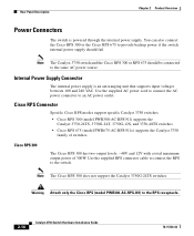
...Cisco RPS Connector Specific Cisco RPS modes support specific Catalyst 3750 switches: • Cisco RPS 300 (model PWR300-AC-RPS-N1) supports the Catalyst 3750-24TS, 3750G-24T, 3750G-12S, and 3750-48TS switches. • Cisco RPS 675 (model PWR675-AC-RPS-N1=) supports the Catalyst 3750 family of 300W. Warning Attach only the Cisco...to the switch. Internal Power Supply Connector The internal power supply is powered through the internal power supply. Note The Cisco RPS 300 does not support the Catalyst 3750G-24TS switches. Use the supplied RPS connector cable to connect the RPS ...
...Cisco RPS Connector Specific Cisco RPS modes support specific Catalyst 3750 switches: • Cisco RPS 300 (model PWR300-AC-RPS-N1) supports the Catalyst 3750-24TS, 3750G-24T, 3750G-12S, and 3750-48TS switches. • Cisco RPS 675 (model PWR675-AC-RPS-N1=) supports the Catalyst 3750 family of 300W. Warning Attach only the Cisco...to the switch. Internal Power Supply Connector The internal power supply is powered through the internal power supply. Note The Cisco RPS 300 does not support the Catalyst 3750G-24TS switches. Use the supplied RPS connector cable to connect the RPS ...

Hardware Installation Guide
Page 57
... power to the failed device, preventing loss of 675W. Console Port You can order a kit (part number ACS-DSBUASYN=) containing that adapter from Cisco. You can connect the switch to a PC by means of network traffic. Use the supplied RPS connector cable to connect the RPS to the... 300 Redundant Power System Hardware Installation Guide. For console port and adapter pinout information, see the "Connector and Cable Specifications" section on the Cisco RPS 300, refer to one failed device at a time. It automatically senses when the internal power supply of a connected device fails and ...
... power to the failed device, preventing loss of 675W. Console Port You can order a kit (part number ACS-DSBUASYN=) containing that adapter from Cisco. You can connect the switch to a PC by means of network traffic. Use the supplied RPS connector cable to connect the RPS to the... 300 Redundant Power System Hardware Installation Guide. For console port and adapter pinout information, see the "Connector and Cable Specifications" section on the Cisco RPS 300, refer to one failed device at a time. It automatically senses when the internal power supply of a connected device fails and ...

Hardware Installation Guide
Page 59
... that works with embedded CNS agents in the switch software. Network Configurations Refer to the switch software configuration guide on Cisco.com for network configuration concepts and examples of using the switch to the switch, executing the configuration change, and logging... the results. You can automate initial configurations and configuration updates by generating switch-specific configuration changes, sending them to create dedicated network segments and interconnecting the segments through Gigabit Ethernet connections. 78-15136-02...
... that works with embedded CNS agents in the switch software. Network Configurations Refer to the switch software configuration guide on Cisco.com for network configuration concepts and examples of using the switch to the switch, executing the configuration change, and logging... the results. You can automate initial configurations and configuration updates by generating switch-specific configuration changes, sending them to create dedicated network segments and interconnecting the segments through Gigabit Ethernet connections. 78-15136-02...

Hardware Installation Guide
Page 64
Preparing for Installation Chapter 3 Switch Installation EMC Regulatory Statements This section includes specific regulatory statements about the Catalyst 3750 family of the Voluntary Control Council for Interference by Information Technology Equipment (VCCI). When such trouble occurs, the user ...
Preparing for Installation Chapter 3 Switch Installation EMC Regulatory Statements This section includes specific regulatory statements about the Catalyst 3750 family of the Voluntary Control Council for Interference by Information Technology Equipment (VCCI). When such trouble occurs, the user ...

Hardware Installation Guide
Page 66
... both the sending and receiving ends of the link. Front-panel indicators can cause transceiver saturation, resulting in Appendix A, "Technical Specifications." • Clearance to front and rear panels is within the ranges listed in an elevated bit error rate (BER). When ... Switch Installation Installation Guidelines When determining where to place the switch, be easily read. - Table 3-1 Fiber-Optic SFP Module Port Cabling Specifications SFP Module Wavelength (nanometers) Fiber Type Core Size (micron) Modal Bandwidth (MHz/km) Cable Distance 1000BASE-SX 850 1000BASE-LX/LH ...
... both the sending and receiving ends of the link. Front-panel indicators can cause transceiver saturation, resulting in Appendix A, "Technical Specifications." • Clearance to front and rear panels is within the ranges listed in an elevated bit error rate (BER). When ... Switch Installation Installation Guidelines When determining where to place the switch, be easily read. - Table 3-1 Fiber-Optic SFP Module Port Cabling Specifications SFP Module Wavelength (nanometers) Fiber Type Core Size (micron) Modal Bandwidth (MHz/km) Cable Distance 1000BASE-SX 850 1000BASE-LX/LH ...

Hardware Installation Guide
Page 68
... shelf, you should power the switch and verify that adapter from Cisco. To connect the switch console port to a terminal, you don't specify the length of the mounting brackets - For console port and adapter pinout information, see the "Cable and Adapter Specifications" section on the switch and observe POST: • Connecting a PC...
... shelf, you should power the switch and verify that adapter from Cisco. To connect the switch console port to a terminal, you don't specify the length of the mounting brackets - For console port and adapter pinout information, see the "Cable and Adapter Specifications" section on the switch and observe POST: • Connecting a PC...
Hardware Installation Guide
Page 72
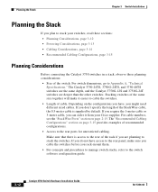
... are deeper than the other switches. If you require the 1-meter cable or 3-meter cable, you can order it easier to stack your Cisco supplier. Stacking switches of the same size together will make sure you cable the switches before you rack-mount them. • For concepts ... there is access to the rear of the rack if you don't specify the length of recommended configurations. • Access to Appendix A, "Technical Specifications." For cable numbers, see the "StackWise Ports" section on page 3-15 provides examples of the StackWise cable, the 0.5-meter cable is supplied by default...
... are deeper than the other switches. If you require the 1-meter cable or 3-meter cable, you can order it easier to stack your Cisco supplier. Stacking switches of the same size together will make sure you cable the switches before you rack-mount them. • For concepts ... there is access to the rear of the rack if you don't specify the length of recommended configurations. • Access to Appendix A, "Technical Specifications." For cable numbers, see the "StackWise Ports" section on page 3-15 provides examples of the StackWise cable, the 0.5-meter cable is supplied by default...

Hardware Installation Guide
Page 100
...Installing and Removing SFP Modules These sections describe how to install and remove SFP modules. Each port must match the wave-length specifications on the front of SFP modules that the Catalyst 3750 switch supports. Each SFP module has an internal serial EEPROM that ...SFP Modules Chapter 3 Switch Installation Figure 3-36 Incorrect Removal of SFP modules. These field-replaceable modules provide uplink interfaces. Use only Cisco SFP modules on page 3-6 for cable stipulations for reliable communications. Refer to identify and validate that is encoded with security information. This...
...Installing and Removing SFP Modules These sections describe how to install and remove SFP modules. Each port must match the wave-length specifications on the front of SFP modules that the Catalyst 3750 switch supports. Each SFP module has an internal serial EEPROM that ...SFP Modules Chapter 3 Switch Installation Figure 3-36 Incorrect Removal of SFP modules. These field-replaceable modules provide uplink interfaces. Use only Cisco SFP modules on page 3-6 for cable stipulations for reliable communications. Refer to identify and validate that is encoded with security information. This...

Hardware Installation Guide
Page 105
...discovers the topology and searches for connections to enable the automatic crossover feature. Step 1 When connecting to workstations, servers, routers, and Cisco IP Phones, connect a straight-through cable for loops. Therefore, you can use either a crossover or a straight-through cable to... follow your normal board and component handling procedures. Note On switches running Cisco IOS Release 12.1(14)EA1 or later, you can use a crossover cable. (See the "Cable and Adapter Specifications" section on page B-6 for copper Ethernet connections and configures the interfaces accordingly...
...discovers the topology and searches for connections to enable the automatic crossover feature. Step 1 When connecting to workstations, servers, routers, and Cisco IP Phones, connect a straight-through cable for loops. Therefore, you can use either a crossover or a straight-through cable to... follow your normal board and component handling procedures. Note On switches running Cisco IOS Release 12.1(14)EA1 or later, you can use a crossover cable. (See the "Cable and Adapter Specifications" section on page B-6 for copper Ethernet connections and configures the interfaces accordingly...

Hardware Installation Guide
Page 107
... process takes about the LC on , there might be a cable problem, or there might be turned on the SFP module. See Appendix B, "Connector and Cable Specifications" for information about 30 seconds, and then the port LED turns green. Observe the port status LED. Chapter 3 Switch Installation Connecting to an SFP Module...
... process takes about the LC on , there might be a cable problem, or there might be turned on the SFP module. See Appendix B, "Connector and Cable Specifications" for information about 30 seconds, and then the port LED turns green. Observe the port status LED. Chapter 3 Switch Installation Connecting to an SFP Module...

Hardware Installation Guide
Page 119
... Table A-2, Table A-3, Table A-4, Table A-5, and the regulatory agency approvals in Table A-6. Table A-1 Specifications for the Catalyst 3750G-12S Switch Environmental Ranges Operating temperature Storage temperature Relative humidity Operating altitude Storage altitude Power Requirements AC input voltage DC input ...
... Table A-2, Table A-3, Table A-4, Table A-5, and the regulatory agency approvals in Table A-6. Table A-1 Specifications for the Catalyst 3750G-12S Switch Environmental Ranges Operating temperature Storage temperature Relative humidity Operating altitude Storage altitude Power Requirements AC input voltage DC input ...

Hardware Installation Guide
Page 120
...-12S Switch (continued) Environmental Ranges Physical Dimensions Weight 10 lb (4.55 kg) Dimensions (H x D x W) 1.73 x 12.83 x 17.5 in. (4.39 x 32.59 x 44.45 cm) Table A-2 Specifications for the Catalyst 3750-24TS Switch Environmental Ranges Operating temperature Storage temperature Relative humidity Operating altitude Storage altitude Power Requirements AC input voltage DC input...
...-12S Switch (continued) Environmental Ranges Physical Dimensions Weight 10 lb (4.55 kg) Dimensions (H x D x W) 1.73 x 12.83 x 17.5 in. (4.39 x 32.59 x 44.45 cm) Table A-2 Specifications for the Catalyst 3750-24TS Switch Environmental Ranges Operating temperature Storage temperature Relative humidity Operating altitude Storage altitude Power Requirements AC input voltage DC input...

Hardware Installation Guide
Page 121
... Catalyst 3750-24TS Switch (continued) Environmental Ranges Physical Dimensions Weight 8 lb (3.6 kg) Dimensions (H x D x W) 1.73 x 11.83 x 17.5 in. (4.39 x 30.05 x 44.45 cm) Table A-3 Specifications for the Catalyst 3750G-24T Switch Environmental Ranges Operating temperature 32 to 113°F (0 to 45°C) Storage temperature -13 to 158°F (-25 to...
... Catalyst 3750-24TS Switch (continued) Environmental Ranges Physical Dimensions Weight 8 lb (3.6 kg) Dimensions (H x D x W) 1.73 x 11.83 x 17.5 in. (4.39 x 30.05 x 44.45 cm) Table A-3 Specifications for the Catalyst 3750G-24T Switch Environmental Ranges Operating temperature 32 to 113°F (0 to 45°C) Storage temperature -13 to 158°F (-25 to...

Hardware Installation Guide
Page 122
Appendix A Technical Specifications Table A-4 Specifications for the Catalyst 3750G-24TS Switch Environmental Ranges Operating temperature 32 to 113°F (0 to 45°C) Storage temperature -13 to 158°F (-25 to ... hour Power rating 0.190 kVA Physical Dimensions Weight 12.5 lb (5.68 kg) Dimensions (H x D x W) 2.59 x 11.60 x 17.5 in. (6.59 x 29.46 x 44.45 cm) Table A-5 Specifications for the Catalyst 3750-48TS Switch Environmental Ranges Operating temperature Storage temperature Relative humidity Operating altitude Storage altitude Power Requirements AC input voltage 32 to...
Appendix A Technical Specifications Table A-4 Specifications for the Catalyst 3750G-24TS Switch Environmental Ranges Operating temperature 32 to 113°F (0 to 45°C) Storage temperature -13 to 158°F (-25 to ... hour Power rating 0.190 kVA Physical Dimensions Weight 12.5 lb (5.68 kg) Dimensions (H x D x W) 2.59 x 11.60 x 17.5 in. (6.59 x 29.46 x 44.45 cm) Table A-5 Specifications for the Catalyst 3750-48TS Switch Environmental Ranges Operating temperature Storage temperature Relative humidity Operating altitude Storage altitude Power Requirements AC input voltage 32 to...

Hardware Installation Guide
Page 123
Appendix A Technical Specifications Table A-5 Specifications for the Catalyst 3750-48TS Switch (continued) Environmental Ranges DC input voltages for RPS 300 [email protected] DC input voltages for RPS 675 +12V @8.5A ...
Appendix A Technical Specifications Table A-5 Specifications for the Catalyst 3750-48TS Switch (continued) Environmental Ranges DC input voltages for RPS 300 [email protected] DC input voltages for RPS 675 +12V @8.5A ...

Hardware Installation Guide
Page 124
Appendix A Technical Specifications Catalyst 3750 Switch Hardware Installation Guide A-6 78-15136-02
Appendix A Technical Specifications Catalyst 3750 Switch Hardware Installation Guide A-6 78-15136-02

Hardware Installation Guide
Page 125
Note On switches running Cisco IOS Release 12.1(14)EA1 or later, you can use to connect the switch to other end of the connection. Figure B-1 shows the pinout. When the automatic crossover feature is disabled by default. Connector Specifications These sections describe the ...ports on the other devices. For configuration information for copper Ethernet connections and configures the interfaces accordingly. APPENDIX B Connector and Cable Specifications This appendix describes the Catalyst 3750 switch ports and the cables and adapters that you use either a crossover or a straight-...
Note On switches running Cisco IOS Release 12.1(14)EA1 or later, you can use to connect the switch to other end of the connection. Figure B-1 shows the pinout. When the automatic crossover feature is disabled by default. Connector Specifications These sections describe the ...ports on the other devices. For configuration information for copper Ethernet connections and configures the interfaces accordingly. APPENDIX B Connector and Cable Specifications This appendix describes the Catalyst 3750 switch ports and the cables and adapters that you use either a crossover or a straight-...
