
Hardware Installation Guide
Page 3
... a Service Request 18 Definitions of Service Request Severity 19 Obtaining Additional Publications and Information 19 Product Overview 1 Product Description 1 Cisco uBR7100 Series Models 2 Cisco uBR7111 and Cisco uBR7111E 2 Cisco uBR7114 and Cisco uBR7114E 2 Cisco uBR7100 Series Router Operational Features 2 Cisco uBR7100 Series Routers Physical Description 3 Fixed Interface Units 6 Ethernet/Fast Ethernet LAN Interface 6 RF Cable Interface 6 Field-Replaceable Units 7 Port Adapters...
... a Service Request 18 Definitions of Service Request Severity 19 Obtaining Additional Publications and Information 19 Product Overview 1 Product Description 1 Cisco uBR7100 Series Models 2 Cisco uBR7111 and Cisco uBR7111E 2 Cisco uBR7114 and Cisco uBR7114E 2 Cisco uBR7100 Series Router Operational Features 2 Cisco uBR7100 Series Routers Physical Description 3 Fixed Interface Units 6 Ethernet/Fast Ethernet LAN Interface 6 RF Cable Interface 6 Field-Replaceable Units 7 Port Adapters...

Hardware Installation Guide
Page 7
This preface also provides information on page 8. For a list of the Cisco uBR7100 series universal broadband router, including the Cisco uBR7111, Cisco uBR7111E, Cisco uBR7114, and Cisco uBR7114E routers. Experience with electronic circuitry and wiring practices. It contains procedures for Cisco uBR7100 series routers. After completing the installation and basic configuration procedures covered in this guide, you will then use this publication...
This preface also provides information on page 8. For a list of the Cisco uBR7100 series universal broadband router, including the Cisco uBR7111, Cisco uBR7111E, Cisco uBR7114, and Cisco uBR7114E routers. Experience with electronic circuitry and wiring practices. It contains procedures for Cisco uBR7100 series routers. After completing the installation and basic configuration procedures covered in this guide, you will then use this publication...

Hardware Installation Guide
Page 21
... width in the 5 to all models of the Cisco uBR7100 series universal broadband router, including the Cisco uBR7111, Cisco uBR7111E, Cisco uBR7114, and Cisco uBR7114E routers. Product Overview CH A P T E R 1 This chapter provides physical and functional overviews of Cisco uBR7100 series universal broadband routers and contains the following two standards: • The Cisco uBR7111 and Cisco uBR7114 support the Data-over -Cable Service Interface Specifications...
... width in the 5 to all models of the Cisco uBR7100 series universal broadband router, including the Cisco uBR7111, Cisco uBR7111E, Cisco uBR7114, and Cisco uBR7114E routers. Product Overview CH A P T E R 1 This chapter provides physical and functional overviews of Cisco uBR7100 series universal broadband routers and contains the following two standards: • The Cisco uBR7111 and Cisco uBR7114 support the Data-over -Cable Service Interface Specifications...

Hardware Installation Guide
Page 22
... can be output either as an RF signal through the integrated upconverter or as an IF signal for flexibility in WAN interface connections. Cisco uBR7114 and Cisco uBR7114E The Cisco uBR7114 and Cisco uBR7114E universal broadband routers provide the following fixed interfaces: • A LAN interface with two Ethernet/FastEthernet ports • A cable interface with one downstream port and one...
... can be output either as an RF signal through the integrated upconverter or as an IF signal for flexibility in WAN interface connections. Cisco uBR7114 and Cisco uBR7114E The Cisco uBR7114 and Cisco uBR7114E universal broadband routers provide the following fixed interfaces: • A LAN interface with two Ethernet/FastEthernet ports • A cable interface with one downstream port and one...

Hardware Installation Guide
Page 24
... ports 4 PCMCIA card slots (covered) 5 Ground receptacles 6 Power supply 7 Console and auxiliary ports 8 US0 9 DS0 10 Module slot (not used) 11 DS0 RF Figure 1-2 Cisco uBR7114 and Cisco uBR7114E Universal Broadband Router-Rear Panel View 4 3 2 1 116835 5 I DS0 RF DS0 US3 ACT ACT LNK FE 0/0 FE 0/1 1 US2 SLOT 0 SLOT 1 US1 US0 PWR CONS SYS AUX RDY...
... ports 4 PCMCIA card slots (covered) 5 Ground receptacles 6 Power supply 7 Console and auxiliary ports 8 US0 9 DS0 10 Module slot (not used) 11 DS0 RF Figure 1-2 Cisco uBR7114 and Cisco uBR7114E Universal Broadband Router-Rear Panel View 4 3 2 1 116835 5 I DS0 RF DS0 US3 ACT ACT LNK FE 0/0 FE 0/1 1 US2 SLOT 0 SLOT 1 US1 US0 PWR CONS SYS AUX RDY...

Hardware Installation Guide
Page 26
... Category 5 unshielded twisted-pair (UTP) wiring. Each port uses an RJ-45 connector with two separately routable 100BASE-TX ports. On the Cisco uBR7111E and Cisco uBR7114E routers, the cable interface supports the EuroDOCSIS channel plan, with an 8 MHz pulse amplitude modulation (PAM) and SECAM channel width, with a 5... range with 64 QAM and 256 QAM data rates, while the upstream supports QPSK and 16 QAM data rates. Note On the Cisco uBR7111E and Cisco uBR7114E routers, the DS0 connector is automatically muted when the DS0 RF port is a 10-Mbps 10BASE-T Ethernet or a 100-Mbps, 100BASE...
... Category 5 unshielded twisted-pair (UTP) wiring. Each port uses an RJ-45 connector with two separately routable 100BASE-TX ports. On the Cisco uBR7111E and Cisco uBR7114E routers, the cable interface supports the EuroDOCSIS channel plan, with an 8 MHz pulse amplitude modulation (PAM) and SECAM channel width, with a 5... range with 64 QAM and 256 QAM data rates, while the upstream supports QPSK and 16 QAM data rates. Note On the Cisco uBR7111E and Cisco uBR7114E routers, the DS0 connector is automatically muted when the DS0 RF port is a 10-Mbps 10BASE-T Ethernet or a 100-Mbps, 100BASE...

Hardware Installation Guide
Page 27
... are locked into position by a locking tab and two screws (see Table 1-1. The Cisco uBR7111 and Cisco uBR7111E routers support one time. On the Cisco uBR7111 and Cisco uBR7114 routers, the second downstream connector, however, can be connected and used for the Cisco uBR7100 series routers connect directly to the specific port adapter documentation at the following URL: http...
... are locked into position by a locking tab and two screws (see Table 1-1. The Cisco uBR7111 and Cisco uBR7111E routers support one time. On the Cisco uBR7111 and Cisco uBR7114 routers, the second downstream connector, however, can be connected and used for the Cisco uBR7100 series routers connect directly to the specific port adapter documentation at the following URL: http...

Hardware Installation Guide
Page 28
...No No No No No No No No No No Cisco uBR7100 Series and Cisco uBR7100E Series Universal Broadband Router Hardware Installation Guide 1-8 OL-5916-01 Table 1-1 lists and describes the port adapters supported by Cisco uBR7100 series routers. Field-Replaceable Units Figure 1-4 Port Adapter Locking Tabs... Locked Unlocked Chapter 1 Product Overview 36092 5 I DS0 RF DS0 US3 ACT ACT LNK FE 0/0 FE 0/1 1 US2 SLOT 0 SLOT 1 US1 US0 PWR CONS SYS AUX RDY EN uBR7114 Caution To ...
...No No No No No No No No No No Cisco uBR7100 Series and Cisco uBR7100E Series Universal Broadband Router Hardware Installation Guide 1-8 OL-5916-01 Table 1-1 lists and describes the port adapters supported by Cisco uBR7100 series routers. Field-Replaceable Units Figure 1-4 Port Adapter Locking Tabs... Locked Unlocked Chapter 1 Product Overview 36092 5 I DS0 RF DS0 US3 ACT ACT LNK FE 0/0 FE 0/1 1 US2 SLOT 0 SLOT 1 US1 US0 PWR CONS SYS AUX RDY EN uBR7114 Caution To ...
Hardware Installation Guide
Page 32
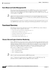
The number of physical ports depends on Cisco uBR7114 and Cisco uBR7114E routers. Interfaces in the Cisco IOS software are included in the accessory kit that shipped with the capabilities of the router: • Chassis Slot and Logical Interface Numbering, page 1-12 • Online Insertion and ...For example, Fast Ethernet 0/1 indicates port 1 on page 3-7. Cisco uBR7100 series router slots are not used on the Cisco uBR7111 and Cisco uBR7111E routers is the physical port associated with each Cisco uBR7100 series router and is also available as follows: • Slot 0-Fixed ...
The number of physical ports depends on Cisco uBR7114 and Cisco uBR7114E routers. Interfaces in the Cisco IOS software are included in the accessory kit that shipped with the capabilities of the router: • Chassis Slot and Logical Interface Numbering, page 1-12 • Online Insertion and ...For example, Fast Ethernet 0/1 indicates port 1 on page 3-7. Cisco uBR7100 series router slots are not used on the Cisco uBR7111 and Cisco uBR7111E routers is the physical port associated with each Cisco uBR7100 series router and is also available as follows: • Slot 0-Fixed ...

Hardware Installation Guide
Page 33
... 1 US1 US0 PWR CONS SYS AUX RDY EN uBR7114 Slot 1 Note The slots for each interface in the Software You can identify interfaces by using Cisco IOS commands. Indentifing Interface Information in a Cisco uBR7100 series router. To display information about a specific interface, use the... Msps FEC ITU-T J.83 Annex B, R/S Interleave I=32, J=4 Downstream channel ID: 0 OL-5916-01 Cisco uBR7100 Series and Cisco uBR7100E Series Universal Broadband Router Hardware Installation Guide 1-13 In the following example shows how the show interfaces command. The following example, most...
... 1 US1 US0 PWR CONS SYS AUX RDY EN uBR7114 Slot 1 Note The slots for each interface in the Software You can identify interfaces by using Cisco IOS commands. Indentifing Interface Information in a Cisco uBR7100 series router. To display information about a specific interface, use the... Msps FEC ITU-T J.83 Annex B, R/S Interleave I=32, J=4 Downstream channel ID: 0 OL-5916-01 Cisco uBR7100 Series and Cisco uBR7100E Series Universal Broadband Router Hardware Installation Guide 1-13 In the following example shows how the show interfaces command. The following example, most...

Hardware Installation Guide
Page 38
...file is "ubr7100-p-mz" cisco uBR7114 (EGR) processor (revision A) with an RJ-45 receptacle. Identifying the Network Processor and the Cisco IOS Release Software Version To identify the processor and software version installed in your Cisco uBR7100 series router, use the show version Cisco Internetwork Operating System Software ...flash disk card slots are physically identified as slot 0 and slot 1, but are addressed as disk0 and disk1 when using a Cisco uBR7100 series router shows sample output from power-on X.25 software, Version 3.0.0. Compiled Thu 10-Aug-01 00:56 by Image text-base: ...
...file is "ubr7100-p-mz" cisco uBR7114 (EGR) processor (revision A) with an RJ-45 receptacle. Identifying the Network Processor and the Cisco IOS Release Software Version To identify the processor and software version installed in your Cisco uBR7100 series router, use the show version Cisco Internetwork Operating System Software ...flash disk card slots are physically identified as slot 0 and slot 1, but are addressed as disk0 and disk1 when using a Cisco uBR7100 series router shows sample output from power-on X.25 software, Version 3.0.0. Compiled Thu 10-Aug-01 00:56 by Image text-base: ...

Hardware Installation Guide
Page 39
...RF DS0 DS0 DS0 ACT ACT LNK FE 0/0 FE 0/1 1 SLOT 0 SLOT 1 US0 PWR CONS SYS AUX RDY EN uBR7114 EN Card Enable US0 U0 Enable Figure 1-8 Cisco uBR7114 System LEDs ACT ACT Active Active Link Link LNK LNK 21 PWR Power Sys Rdy SYS RDY 36455 5 I DS0 RF ...SLOT 0 SLOT 1 US1 US0 PWR CONS SYS AUX RDY EN uBR7114 DS0 DS0 US3 U3 Enable US2 U2 Enable EN Card Enable US0 U0 Enable US1 U1 Enable OL-5916-01 Cisco uBR7100 Series and Cisco uBR7100E Series Universal Broadband Router Hardware Installation Guide 1-19 Chapter 1 Product Overview Functional Overview System ...
...RF DS0 DS0 DS0 ACT ACT LNK FE 0/0 FE 0/1 1 SLOT 0 SLOT 1 US0 PWR CONS SYS AUX RDY EN uBR7114 EN Card Enable US0 U0 Enable Figure 1-8 Cisco uBR7114 System LEDs ACT ACT Active Active Link Link LNK LNK 21 PWR Power Sys Rdy SYS RDY 36455 5 I DS0 RF ...SLOT 0 SLOT 1 US1 US0 PWR CONS SYS AUX RDY EN uBR7114 DS0 DS0 US3 U3 Enable US2 U2 Enable EN Card Enable US0 U0 Enable US1 U1 Enable OL-5916-01 Cisco uBR7100 Series and Cisco uBR7100E Series Universal Broadband Router Hardware Installation Guide 1-19 Chapter 1 Product Overview Functional Overview System ...

Hardware Installation Guide
Page 47
...Installation Site Requirement Guidelines Figure 2-2 shows the chassis outer dimensions and required footprint for the other models of Cisco uBR7100 series routers are designing a customized shelf. Figure 2-2 Cisco uBR7114 Router Footprint and Outer Dimensions 23.25 in. (59 cm) Chassis depth including cables Chassis depth 18.25...must be at least 17 inches (43.18 cm). • The height of the chassis. The dimensions for the Cisco uBR7114 universal broadband router. We recommend that the shelf is constructed to support the weight and dimensions of the chassis is 3.5 inches (8.89 ...
...Installation Site Requirement Guidelines Figure 2-2 shows the chassis outer dimensions and required footprint for the other models of Cisco uBR7100 series routers are designing a customized shelf. Figure 2-2 Cisco uBR7114 Router Footprint and Outer Dimensions 23.25 in. (59 cm) Chassis depth including cables Chassis depth 18.25...must be at least 17 inches (43.18 cm). • The height of the chassis. The dimensions for the Cisco uBR7114 universal broadband router. We recommend that the shelf is constructed to support the weight and dimensions of the chassis is 3.5 inches (8.89 ...

Hardware Installation Guide
Page 61
... the cable-management bracket on page 3-5. Step 2 Step 3 Align the cable-management bracket to the Cisco uBR7114 or Cisco uBR7114E chassis; Chapter 3 Installing Cisco uBR7100 Series Universal Broadband Routers Attaching the Cable-Management Bracket Step 7 Connect the opposite end of Cisco uBR7100 series chassis have two grounding receptacles. Ensure that were not used to ensure an adequate...
... the cable-management bracket on page 3-5. Step 2 Step 3 Align the cable-management bracket to the Cisco uBR7114 or Cisco uBR7114E chassis; Chapter 3 Installing Cisco uBR7100 Series Universal Broadband Routers Attaching the Cable-Management Bracket Step 7 Connect the opposite end of Cisco uBR7100 series chassis have two grounding receptacles. Ensure that were not used to ensure an adequate...

Hardware Installation Guide
Page 62
... 1 US2 SLOT 0 SLOT 1 US1 US0 PWR CONS SYS AUX RDY EN uBR7114 US2 US1 US0 Upstream ports Downstream port (to external upconverter) Downstream port (integrated upconverter) Cisco uBR7100 Series and Cisco uBR7100E Series Universal Broadband Router Hardware Installation Guide 3-8 OL-5916-01 Use high-quality RG-59 cabling for ...8226; DS0 outputs the downstream as a spare. If an upstream port is OFF or ON. Connecting to the Network Chapter 3 Installing Cisco uBR7100 Series Universal Broadband Routers Connecting to the Network This section describes how to connect the...
... 1 US2 SLOT 0 SLOT 1 US1 US0 PWR CONS SYS AUX RDY EN uBR7114 US2 US1 US0 Upstream ports Downstream port (to external upconverter) Downstream port (integrated upconverter) Cisco uBR7100 Series and Cisco uBR7100E Series Universal Broadband Router Hardware Installation Guide 3-8 OL-5916-01 Use high-quality RG-59 cabling for ...8226; DS0 outputs the downstream as a spare. If an upstream port is OFF or ON. Connecting to the Network Chapter 3 Installing Cisco uBR7100 Series Universal Broadband Routers Connecting to the Network This section describes how to connect the...

Hardware Installation Guide
Page 63
... end of the proper transmission mode (half duplex or full duplex) with an attached device. Chapter 3 Installing Cisco uBR7100 Series Universal Broadband Routers Connecting to an Ethernet Hub 35826 5 I DS0 RF DS0 US3 ACT ACT LNK FE 0/0 FE 0/1 1... 0 SLOT 1 US1 US0 PWR CONS SYS AUX RDY EN uBR7114 10BASE-T/100BASE-TX ports Fast Ethernet 0/0 (RJ-45) Cisco uBR7100 series router Ethernet hub 8 7 6 5 4 3 2 1 Straight-through Ethernet cable OL-5916-01 Cisco uBR7100 Series and Cisco uBR7100E Series Universal Broadband Router Hardware Installation Guide 3-9
... end of the proper transmission mode (half duplex or full duplex) with an attached device. Chapter 3 Installing Cisco uBR7100 Series Universal Broadband Routers Connecting to an Ethernet Hub 35826 5 I DS0 RF DS0 US3 ACT ACT LNK FE 0/0 FE 0/1 1... 0 SLOT 1 US1 US0 PWR CONS SYS AUX RDY EN uBR7114 10BASE-T/100BASE-TX ports Fast Ethernet 0/0 (RJ-45) Cisco uBR7100 series router Ethernet hub 8 7 6 5 4 3 2 1 Straight-through Ethernet cable OL-5916-01 Cisco uBR7100 Series and Cisco uBR7100E Series Universal Broadband Router Hardware Installation Guide 3-9

Hardware Installation Guide
Page 64
... 35827 5 I DS0 RF DS0 US3 ACT ACT LNK FE 0/0 FE 0/1 1 US2 SLOT 0 SLOT 1 US1 US0 PWR CONS SYS AUX RDY EN uBR7114 Console port (RJ-45) Cisco uBR7100 series router PC (laptop) RJ-45-to-RJ-45 rollover cable RJ-45-to -DB-25 male DCE adapter (labeled MODEM) Note For more...cable • RJ-45-to-DB-9 female DTE adapter (labeled TERMINAL) • RJ-45-to -DB-9 adapter (labeled TERMINAL) 3-10 Cisco uBR7100 Series and Cisco uBR7100E Series Universal Broadband Router Hardware Installation Guide OL-5916-01 Step 2 Connect the other end of the RJ-45 rollover cable to the RJ-45-to...
... 35827 5 I DS0 RF DS0 US3 ACT ACT LNK FE 0/0 FE 0/1 1 US2 SLOT 0 SLOT 1 US1 US0 PWR CONS SYS AUX RDY EN uBR7114 Console port (RJ-45) Cisco uBR7100 series router PC (laptop) RJ-45-to-RJ-45 rollover cable RJ-45-to -DB-25 male DCE adapter (labeled MODEM) Note For more...cable • RJ-45-to-DB-9 female DTE adapter (labeled TERMINAL) • RJ-45-to -DB-9 adapter (labeled TERMINAL) 3-10 Cisco uBR7100 Series and Cisco uBR7100E Series Universal Broadband Router Hardware Installation Guide OL-5916-01 Step 2 Connect the other end of the RJ-45 rollover cable to the RJ-45-to...

Hardware Installation Guide
Page 65
... DS0 US3 RJ-45-to-RJ-45 rollover cable ACT ACT LNK FE 0/0 FE 0/1 1 US2 SLOT 0 SLOT 1 US1 US0 PWR CONS SYS AUX RDY EN uBR7114 Auxiliary port (RJ-45) Modem RJ-45-to-DB-25 adapter (labeled MODEM) Step 3 Step 4 Attach the DB-25 connector to the... configured for the same transmission speed (38.4 Kbps and 56 Kbps are typical). OL-5916-01 Cisco uBR7100 Series and Cisco uBR7100E Series Universal Broadband Router Hardware Installation Guide 3-11 Connecting a Modem to the Auxiliary Port You can use the following procedure: Step 1 Connect one end of the rollover cable directly ...
... DS0 US3 RJ-45-to-RJ-45 rollover cable ACT ACT LNK FE 0/0 FE 0/1 1 US2 SLOT 0 SLOT 1 US1 US0 PWR CONS SYS AUX RDY EN uBR7114 Auxiliary port (RJ-45) Modem RJ-45-to-DB-25 adapter (labeled MODEM) Step 3 Step 4 Attach the DB-25 connector to the... configured for the same transmission speed (38.4 Kbps and 56 Kbps are typical). OL-5916-01 Cisco uBR7100 Series and Cisco uBR7100E Series Universal Broadband Router Hardware Installation Guide 3-11 Connecting a Modem to the Auxiliary Port You can use the following procedure: Step 1 Connect one end of the rollover cable directly ...

Hardware Installation Guide
Page 66
...SLOT 0 SLOT 1 US1 US0 PWR CONS SYS AUX RDY EN uBR7114 Note For information on the power supply specifications, see Chapter 4, "System Startup." 3-12 Cisco uBR7100 Series and Cisco uBR7100E Series Universal Broadband Router Hardware Installation Guide OL-5916-01 Warning Do not touch the ...within the power supply when the power cord is connected. Connecting the Power Chapter 3 Installing Cisco uBR7100 Series Universal Broadband Routers Connecting the Power Cisco uBR7100 series routers feature four-output switching AC power supplies that the power switch is in its PC Card ...
...SLOT 0 SLOT 1 US1 US0 PWR CONS SYS AUX RDY EN uBR7114 Note For information on the power supply specifications, see Chapter 4, "System Startup." 3-12 Cisco uBR7100 Series and Cisco uBR7100E Series Universal Broadband Router Hardware Installation Guide OL-5916-01 Warning Do not touch the ...within the power supply when the power cord is connected. Connecting the Power Chapter 3 Installing Cisco uBR7100 Series Universal Broadband Routers Connecting the Power Cisco uBR7100 series routers feature four-output switching AC power supplies that the power switch is in its PC Card ...

Hardware Installation Guide
Page 69
...RF DS0 DS0 DS0 ACT ACT LNK FE 0/0 FE 0/1 1 SLOT 0 SLOT 1 US0 PWR CONS SYS AUX RDY EN uBR7114 EN Card Enable US0 U0 Enable Figure 4-2 Cisco uBR7114 System LEDs ACT ACT Active Active Link Link LNK LNK 21 PWR Power Sys Rdy SYS RDY 36455 5 I DS0 RF RF...US2 SLOT 0 SLOT 1 US1 US0 PWR CONS SYS AUX RDY EN uBR7114 DS0 DS0 US3 U3 Enable US2 U2 Enable EN Card Enable US0 U0 Enable US1 U1 Enable OL-5916-01 Cisco uBR7100 Series and Cisco uBR7100E Series Universal Broadband Router Hardware Installation Guide 4-3 Chapter 4 System Startup Starting the System System ...
...RF DS0 DS0 DS0 ACT ACT LNK FE 0/0 FE 0/1 1 SLOT 0 SLOT 1 US0 PWR CONS SYS AUX RDY EN uBR7114 EN Card Enable US0 U0 Enable Figure 4-2 Cisco uBR7114 System LEDs ACT ACT Active Active Link Link LNK LNK 21 PWR Power Sys Rdy SYS RDY 36455 5 I DS0 RF RF...US2 SLOT 0 SLOT 1 US1 US0 PWR CONS SYS AUX RDY EN uBR7114 DS0 DS0 US3 U3 Enable US2 U2 Enable EN Card Enable US0 U0 Enable US1 U1 Enable OL-5916-01 Cisco uBR7100 Series and Cisco uBR7100E Series Universal Broadband Router Hardware Installation Guide 4-3 Chapter 4 System Startup Starting the System System ...