
Hardware Installation Guide
Page 8
...If you purchased the product. Actual delivery times can vary, depending on the customer location. Cisco reserves the right to refund the purchase price as the original end user continues to own or use commercially reasonable efforts to ship a replacement part within ten (...Return Materials Authorization (RMA) Number Contact the company from the announcement of the discontinuance. Cisco Limited Lifetime Hardware Warranty Terms Duration of Hardware Warranty A Cisco product hardware warranty is supported for as long as its service center will use the product, provided that the fan...
...If you purchased the product. Actual delivery times can vary, depending on the customer location. Cisco reserves the right to refund the purchase price as the original end user continues to own or use commercially reasonable efforts to ship a replacement part within ten (...Return Materials Authorization (RMA) Number Contact the company from the announcement of the discontinuance. Cisco Limited Lifetime Hardware Warranty Terms Duration of Hardware Warranty A Cisco product hardware warranty is supported for as long as its service center will use the product, provided that the fan...
Hardware Installation Guide
Page 31
... does not take precedence over the 10/100/1000 port. These transceiver modules are labeled Uplink Port 1 and Uplink Port 2. The SFP modules support nominal wavelengths from the switch to connected devices are logically bundled as a vertical column on Uplink Port 1. When determining where to place the switch..., be connecting to other end of the two physical ports, either the SFP module port or the 10/100/1000 port on the front panel and are field-replaceable....
... does not take precedence over the 10/100/1000 port. These transceiver modules are labeled Uplink Port 1 and Uplink Port 2. The SFP modules support nominal wavelengths from the switch to connected devices are logically bundled as a vertical column on Uplink Port 1. When determining where to place the switch..., be connecting to other end of the two physical ports, either the SFP module port or the 10/100/1000 port on the front panel and are field-replaceable....

Hardware Installation Guide
Page 51
...Regulatory Compliance and Safety Information for the Catalyst 2950 Switch • AC power cord (not shipped with shielded cable grounded at both ends. Front-panel DC power connector on switches other than normal room temperature. • Cabling is sufficient for unrestricted cabling. - ...Four rubber feet for mounting the switch on the Catalyst 2950G-24-EI-DC switch is missing or damaged, contact your Cisco representative or reseller for support. Verifying Package Contents Note Carefully remove the contents from a switch to an attached device cannot exceed 3 feet (1 meter)....
...Regulatory Compliance and Safety Information for the Catalyst 2950 Switch • AC power cord (not shipped with shielded cable grounded at both ends. Front-panel DC power connector on switches other than normal room temperature. • Cabling is sufficient for unrestricted cabling. - ...Four rubber feet for mounting the switch on the Catalyst 2950G-24-EI-DC switch is missing or damaged, contact your Cisco representative or reseller for support. Verifying Package Contents Note Carefully remove the contents from a switch to an attached device cannot exceed 3 feet (1 meter)....

Hardware Installation Guide
Page 69
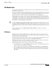
See the Catalyst 2950 LRE release notes for the list of SFP modules that has a bale-clasp latch. Use only Cisco SFP modules on the other end of latch your SFP module documentation. Refer to identify and validate that the SFP module meets the requirements for reliable communications, ...2-29 shows an SFP module with an actuator button latch. • Figure 2-30 shows an SFP module that the Catalyst 2950 LRE switch supports. Each SFP module has an internal serial EEPROM that you do not install or remove the SFP module with security information. Caution We strongly recommend...
See the Catalyst 2950 LRE release notes for the list of SFP modules that has a bale-clasp latch. Use only Cisco SFP modules on the other end of latch your SFP module documentation. Refer to identify and validate that the SFP module meets the requirements for reliable communications, ...2-29 shows an SFP module with an actuator button latch. • Figure 2-30 shows an SFP module that the Catalyst 2950 LRE switch supports. Each SFP module has an internal serial EEPROM that you do not install or remove the SFP module with security information. Caution We strongly recommend...
Hardware Installation Guide
Page 73
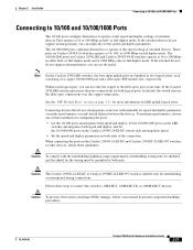
.../100/1000 ports on the Catalyst 2950G-24-EI-DC switch only autonegotiate speed. • Set the speed and duplex parameters on both ends of the connection. Follow these guidelines: Caution To comply with manually set speed and duplex parameters can explicitly set the speed. The 10...connections over the copper connections. If the attached devices do not support autonegotiation, you can set the speed and duplex parameters. If the Catalyst 2950 LRE switch senses more information on Catalyst 2950 LRE and Catalyst 2950T-48-SI switches operate at 10 or 100 Mbps in full-duplex mode....
.../100/1000 ports on the Catalyst 2950G-24-EI-DC switch only autonegotiate speed. • Set the speed and duplex parameters on both ends of the connection. Follow these guidelines: Caution To comply with manually set speed and duplex parameters can explicitly set the speed. The 10...connections over the copper connections. If the attached devices do not support autonegotiation, you can set the speed and duplex parameters. If the Catalyst 2950 LRE switch senses more information on Catalyst 2950 LRE and Catalyst 2950T-48-SI switches operate at 10 or 100 Mbps in full-duplex mode....
Hardware Installation Guide
Page 84
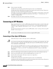
...how to 1000BASE-T SFP Modules" section. The LED turns amber while STP discovers the network topology and searches for loops. Insert the other cable end into the SFP module port (see the "Connecting to SFP Modules Chapter 2 Installation Step 3 Step 4 Observe the port status LED. Note See...Caution Do not remove the rubber plugs from the SFP module port or the rubber caps from contamination and ambient light. Insert one end of supported SFP modules. Observe the port status LED. The LED turns amber while the STP discovers the network topology and searches for loops. ...
...how to 1000BASE-T SFP Modules" section. The LED turns amber while STP discovers the network topology and searches for loops. Insert the other cable end into the SFP module port (see the "Connecting to SFP Modules Chapter 2 Installation Step 3 Step 4 Observe the port status LED. Note See...Caution Do not remove the rubber plugs from the SFP module port or the rubber caps from contamination and ambient light. Insert one end of supported SFP modules. Observe the port status LED. The LED turns amber while the STP discovers the network topology and searches for loops. ...
Hardware Installation Guide
Page 103
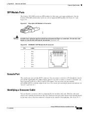
...8 TP3- 60915 Console Port The console port uses an 8-pin RJ-45 connector. Hold the cable ends side-by comparing the two modular cable ends. If you want to connect a switch to a terminal, you need to provide an RJ-45-...Connector Specifications SFP Module Ports The Catalyst 2950 LRE switch uses SFP modules for a list of supported SFP modules. Figure B-7 Fiber-Optic SFP Module LC Connector 58476 Warning Invisible laser radiation may...the outside of the left plug should be emitted from Cisco. See the Catalyst 2950 LRE switch release notes for fiber-optic and copper uplink ports....
...8 TP3- 60915 Console Port The console port uses an 8-pin RJ-45 connector. Hold the cable ends side-by comparing the two modular cable ends. If you want to connect a switch to a terminal, you need to provide an RJ-45-...Connector Specifications SFP Module Ports The Catalyst 2950 LRE switch uses SFP modules for a list of supported SFP modules. Figure B-7 Fiber-Optic SFP Module LC Connector 58476 Warning Invisible laser radiation may...the outside of the left plug should be emitted from Cisco. See the Catalyst 2950 LRE switch release notes for fiber-optic and copper uplink ports....


