
Hardware Installation Guide
Page 5
...the U.S. and Aironet, ASIST, BPX, Catalyst, CCDA, CCDP, CCIE, CCNA, CCNP, Cisco, the Cisco Certified Internetwork Expert logo, Cisco IOS, the Cisco IOS logo, Cisco Press, Cisco Systems, Cisco Systems Capital, the Cisco Systems logo, Empowering the Internet Generation, Enterprise/Solver, EtherChannel, EtherSwitch, Fast Step, GigaStack...in this document or Web site are the property of Cisco Systems, Inc.; The use of Cisco Systems, Inc. All other countries. CCIP, CCSP, the Cisco Arrow logo, the Cisco Powered Network mark, Cisco Unity, Follow Me Browsing, FormShare, and StackWise are ...
...the U.S. and Aironet, ASIST, BPX, Catalyst, CCDA, CCDP, CCIE, CCNA, CCNP, Cisco, the Cisco Certified Internetwork Expert logo, Cisco IOS, the Cisco IOS logo, Cisco Press, Cisco Systems, Cisco Systems Capital, the Cisco Systems logo, Empowering the Internet Generation, Enterprise/Solver, EtherChannel, EtherSwitch, Fast Step, GigaStack...in this document or Web site are the property of Cisco Systems, Inc.; The use of Cisco Systems, Inc. All other countries. CCIP, CCSP, the Cisco Arrow logo, the Cisco Powered Network mark, Cisco Unity, Follow Me Browsing, FormShare, and StackWise are ...
Hardware Installation Guide
Page 7
...-ROM xxiv Ordering Documentation xxiv Documentation Feedback xxv Obtaining Technical Assistance xxv Cisco.com xxvi Technical Assistance Center xxvi Cisco TAC Website xxvii Cisco TAC Escalation Center xxvii Obtaining Additional Publications and Information xxviii Using Express Setup 1-1 Taking Out What You Need 1-2 Powering On the Switch 1-3 Starting Express Setup 1-4 Configuring the Switch Settings 1-9 Verifying...
...-ROM xxiv Ordering Documentation xxiv Documentation Feedback xxv Obtaining Technical Assistance xxv Cisco.com xxvi Technical Assistance Center xxvi Cisco TAC Website xxvii Cisco TAC Escalation Center xxvii Obtaining Additional Publications and Information xxviii Using Express Setup 1-1 Taking Out What You Need 1-2 Powering On the Switch 1-3 Starting Express Setup 1-4 Configuring the Switch Settings 1-9 Verifying...
Hardware Installation Guide
Page 8
... 2-7 SFP Modules 2-7 LEDs 2-8 System LED 2-9 RPS LED 2-9 Master LED 2-10 Port LEDs and Modes 2-10 Rear Panel Description 2-14 StackWise Ports 2-15 Power Connectors 2-16 Internal Power Supply Connector 2-16 Cisco RPS Connector 2-16 Console Port 2-17 Management Options 2-18 Network Configurations 2-19 Switch Installation 3-1 Preparing for Installation 3-1 Warnings 3-2 EMC Regulatory Statements 3-4 Catalyst...
... 2-7 SFP Modules 2-7 LEDs 2-8 System LED 2-9 RPS LED 2-9 Master LED 2-10 Port LEDs and Modes 2-10 Rear Panel Description 2-14 StackWise Ports 2-15 Power Connectors 2-16 Internal Power Supply Connector 2-16 Cisco RPS Connector 2-16 Console Port 2-17 Management Options 2-18 Network Configurations 2-19 Switch Installation 3-1 Preparing for Installation 3-1 Warnings 3-2 EMC Regulatory Statements 3-4 Catalyst...

Hardware Installation Guide
Page 9
... Package Contents 3-7 Verifying Switch Operation 3-8 Connecting a PC or Terminal to the Console Port 3-8 Powering On the Switch and Running POST 3-10 Powering Off the Switch and Disconnecting the Console Port 3-11 Planning the Stack 3-12 Planning Considerations 3-12 Powering Considerations 3-13 Cabling Considerations 3-14 Recommended Cabling Configurations 3-15 Installing the Switch 3-17 Rack...
... Package Contents 3-7 Verifying Switch Operation 3-8 Connecting a PC or Terminal to the Console Port 3-8 Powering On the Switch and Running POST 3-10 Powering Off the Switch and Disconnecting the Console Port 3-11 Planning the Stack 3-12 Planning Considerations 3-12 Powering Considerations 3-13 Cabling Considerations 3-14 Recommended Cabling Configurations 3-15 Installing the Switch 3-17 Rack...
Hardware Installation Guide
Page 11
... Through the Console Port D-3 Taking Out What You Need D-4 Stacking the Switches (Optional) D-5 Connecting to the Console Port D-7 Starting the Terminal Emulation Software D-9 Connecting to a Power Source D-9 Entering the Initial Configuration Information D-10 IP Settings D-10 Completing the Setup Program D-11 78-15136-02 Catalyst 3750 Switch Hardware Installation Guide ix
... Through the Console Port D-3 Taking Out What You Need D-4 Stacking the Switches (Optional) D-5 Connecting to the Console Port D-7 Starting the Terminal Emulation Software D-9 Connecting to a Power Source D-9 Entering the Initial Configuration Information D-10 IP Settings D-10 Completing the Setup Program D-11 78-15136-02 Catalyst 3750 Switch Hardware Installation Guide ix
Hardware Installation Guide
Page 12
Contents E A P P E N D I X INDEX Translated Safety Warnings E-1 Attaching the Cisco RPS (model PWR300-AC-RPS-N1) E-1 Attaching the Cisco RPS (model PWR675-AC-RPS-N1) E-2 Installation Warning E-4 Installation Instructions E-5 Jewelry Removal Warning E-6 Stacking the Chassis Warning...Overtemperature Warning E-14 Working During Lightning Activity E-16 Product Disposal Warning E-17 Chassis Warning for Rack-Mounting and Servicing E-19 Redundant Power Supply Connection Warning E-24 Switch Installation Warning E-25 Restricted Area E-27 Ethernet Cable Shielding in Offices E-28 Laser Beam Exposure E-30...
Contents E A P P E N D I X INDEX Translated Safety Warnings E-1 Attaching the Cisco RPS (model PWR300-AC-RPS-N1) E-1 Attaching the Cisco RPS (model PWR675-AC-RPS-N1) E-2 Installation Warning E-4 Installation Instructions E-5 Jewelry Removal Warning E-6 Stacking the Chassis Warning...Overtemperature Warning E-14 Working During Lightning Activity E-16 Product Disposal Warning E-17 Chassis Warning for Rack-Mounting and Servicing E-19 Redundant Power Supply Connection Warning E-24 Switch Installation Warning E-25 Restricted Area E-27 Ethernet Cable Shielding in Offices E-28 Laser Beam Exposure E-30...
Hardware Installation Guide
Page 14
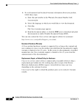
...the document online, or click the PDF icon to view the document. Actual delivery times can also contact the Cisco service and support website for assistance: http://www.cisco.com/public/Support_root.shtml. You can vary, depending on the customer location. Select the language in which you...continues to own or use the product, provided that the fan and power supply warranty is limited to refund the purchase price as its service center will use commercially reasonable efforts to five (5) years. Cisco Limited Lifetime Hardware Warranty Terms 3. Enter this part number in Adobe ...
...the document online, or click the PDF icon to view the document. Actual delivery times can also contact the Cisco service and support website for assistance: http://www.cisco.com/public/Support_root.shtml. You can vary, depending on the customer location. Select the language in which you...continues to own or use the product, provided that the fan and power supply warranty is limited to refund the purchase price as its service center will use commercially reasonable efforts to five (5) years. Cisco Limited Lifetime Hardware Warranty Terms 3. Enter this part number in Adobe ...
Hardware Installation Guide
Page 29
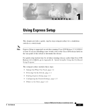
...Express Setup This chapter provides a quick, step-by-step setup procedure for switches running Cisco IOS Release 12.1(14)EA1 or later. The setup procedure includes these steps: • Taking Out What You Need, page 1-2 • Powering On the Switch, page 1-3 • Starting Express Setup, page 1-4 • ...Configuring the Switch Settings, page 1-9 • Where to determine the release. If you are installing a new switch, refer to the Cisco IOS release label on switches running ...
...Express Setup This chapter provides a quick, step-by-step setup procedure for switches running Cisco IOS Release 12.1(14)EA1 or later. The setup procedure includes these steps: • Taking Out What You Need, page 1-2 • Powering On the Switch, page 1-3 • Starting Express Setup, page 1-4 • ...Configuring the Switch Settings, page 1-9 • Where to determine the release. If you are installing a new switch, refer to the Cisco IOS release label on switches running ...

Hardware Installation Guide
Page 30
...Remove the items shown in Figure 1-1 from the switch. Catalyst 3750 Switch Hardware Installation Guide 1-2 78-15136-02 Figure 1-1 Catalyst 3750 Switch and AC Power Cord 1 SYST RPS MASTR STAT 1X DUPLX SPEED STACK MODE 2X 11X 13X 12X 14X 23X Catalyst 3750 SERIES 24X 97175 2 1 Switch 2 AC... power cord You also need to provide an Ethernet (Category 5) straight-through cable (not included), as a DHCP server during the Express Setup procedure, and ...
...Remove the items shown in Figure 1-1 from the switch. Catalyst 3750 Switch Hardware Installation Guide 1-2 78-15136-02 Figure 1-1 Catalyst 3750 Switch and AC Power Cord 1 SYST RPS MASTR STAT 1X DUPLX SPEED STACK MODE 2X 11X 13X 12X 14X 23X Catalyst 3750 SERIES 24X 97175 2 1 Switch 2 AC... power cord You also need to provide an Ethernet (Category 5) straight-through cable (not included), as a DHCP server during the Express Setup procedure, and ...

Hardware Installation Guide
Page 31
Figure 1-3 Connecting the Power 1 STACK 1 STACK 2 CONSOLE 1.2A-100R>06A-A2T4,IN05GV0-~60 HZ DSCPIENPCPO+IUWF1T2IEESvDRFISO@NUR1MP3RPAAELNYMUOATLE 97176 1 Switch 2 2 AC power cord 78-15136-02 Catalyst 3750 Switch Hardware Installation Guide 1-3 Chapter 1 Using Express Setup Figure 1-2 Ethernet Cable Powering On the Switch 89887 Powering On the Switch Complete these steps to power on the switch: Step 1 Connect one end of the AC power cord to the power connector on the switch rear panel, as shown in Figure 1-3.
Figure 1-3 Connecting the Power 1 STACK 1 STACK 2 CONSOLE 1.2A-100R>06A-A2T4,IN05GV0-~60 HZ DSCPIENPCPO+IUWF1T2IEESvDRFISO@NUR1MP3RPAAELNYMUOATLE 97176 1 Switch 2 2 AC power cord 78-15136-02 Catalyst 3750 Switch Hardware Installation Guide 1-3 Chapter 1 Using Express Setup Figure 1-2 Ethernet Cable Powering On the Switch 89887 Powering On the Switch Complete these steps to power on the switch: Step 1 Connect one end of the AC power cord to the power connector on the switch rear panel, as shown in Figure 1-3.

Hardware Installation Guide
Page 32
... a username for the switch, use to local routers and the Internet. For information about troubleshooting a POST failure, see Chapter 4, "Troubleshooting," to determine a course of the power cable to ensure that you plan to configure a switch. If the POST fails, see the "Understanding POST Results" section on page 4-2. The switch acts as... Do not start Express Setup until POST has completed. The MASTR LED is complete, only the SYST and STAT LEDs remain green. After the switch powers on, it begins the power-on a stack master switch.
... a username for the switch, use to local routers and the Internet. For information about troubleshooting a POST failure, see Chapter 4, "Troubleshooting," to determine a course of the power cable to ensure that you plan to configure a switch. If the POST fails, see the "Understanding POST Results" section on page 4-2. The switch acts as... Do not start Express Setup until POST has completed. The MASTR LED is complete, only the SYST and STAT LEDs remain green. After the switch powers on, it begins the power-on a stack master switch.
Hardware Installation Guide
Page 42
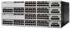
... ports and 4 SFP module slots - For 10/100 ports, autonegotiates the speed and duplex settings - Connection for optional Cisco RPS 300 redundant power system that operates on AC input and supplies backup DC power output to nine switches in half-duplex mode at 10, 100, or 1000 Mbps in full-duplex mode or...
... ports and 4 SFP module slots - For 10/100 ports, autonegotiates the speed and duplex settings - Connection for optional Cisco RPS 300 redundant power system that operates on AC input and supplies backup DC power output to nine switches in half-duplex mode at 10, 100, or 1000 Mbps in full-duplex mode or...
Hardware Installation Guide
Page 43
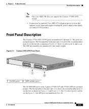
... the Catalyst 3750G-24T and 3750G-24TS are numbered 25 to the family of Catalyst 3750 switches. Chapter 2 Product Overview Front Panel Description Note The Cisco RPS 300 does not support the Catalyst 3750G-24TS switch. - Front Panel Description The Catalyst 3750-24TS 10/100 ports are numbered 1 (left) ...shown in pairs. The first member of the pair (port 1) is above the second member (port 2) on AC input and supplies backup DC power output to 28. 78-15136-02 Catalyst 3750 Switch Hardware Installation Guide 2-3 The SFP port numbers are numbered 1 through 24. Connection for optional...
... the Catalyst 3750G-24T and 3750G-24TS are numbered 25 to the family of Catalyst 3750 switches. Chapter 2 Product Overview Front Panel Description Note The Cisco RPS 300 does not support the Catalyst 3750G-24TS switch. - Front Panel Description The Catalyst 3750-24TS 10/100 ports are numbered 1 (left) ...shown in pairs. The first member of the pair (port 1) is above the second member (port 2) on AC input and supplies backup DC power output to 28. 78-15136-02 Catalyst 3750 Switch Hardware Installation Guide 2-3 The SFP port numbers are numbered 1 through 24. Connection for optional...

Hardware Installation Guide
Page 49
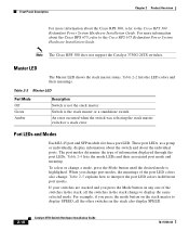
...connected. RPS is unavailable because it does not, the RPS fan could have failed. Press the Standby/Active button on . Contact Cisco Systems. The internal power supply in a fault condition. The RPS is in standby mode or in a switch has failed, and the RPS is providing...), see the "Connecting to this device). 78-15136-02 Catalyst 3750 Switch Hardware Installation Guide 2-9 For information on the System LED colors during power-on page 3-44. Table 2-2 RPS LED Color Off Green Flashing green Amber Flashing amber RPS Status RPS is operating normally. Chapter 2 Product ...
...connected. RPS is unavailable because it does not, the RPS fan could have failed. Press the Standby/Active button on . Contact Cisco Systems. The internal power supply in a fault condition. The RPS is in standby mode or in a switch has failed, and the RPS is providing...), see the "Connecting to this device). 78-15136-02 Catalyst 3750 Switch Hardware Installation Guide 2-9 For information on the System LED colors during power-on page 3-44. Table 2-2 RPS LED Color Off Green Flashing green Amber Flashing amber RPS Status RPS is operating normally. Chapter 2 Product ...
Hardware Installation Guide
Page 50
... the stack master to display SPEED, all the switches in different port modes. For more information about the Cisco RPS 300, refer to the Cisco RPS 300 Redundant Power System Hardware Installation Guide. An error occurred when the switch was selecting the stack master switch or a stack... LED shows the stack master status. Front Panel Description Chapter 2 Product Overview For more information about the Cisco RPS 675, refer to the Cisco RPS 675 Redundant Power System Hardware Installation Guide. To select or change port modes, the meanings of information displayed through the port...
... the stack master to display SPEED, all the switches in different port modes. For more information about the Cisco RPS 300, refer to the Cisco RPS 300 Redundant Power System Hardware Installation Guide. An error occurred when the switch was selecting the stack master switch or a stack... LED shows the stack master status. Front Panel Description Chapter 2 Product Overview For more information about the Cisco RPS 675, refer to the Cisco RPS 675 Redundant Power System Hardware Installation Guide. To select or change port modes, the meanings of information displayed through the port...

Hardware Installation Guide
Page 54
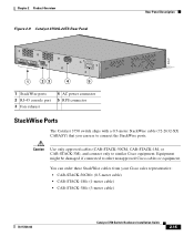
Rear Panel Description Chapter 2 Product Overview Rear Panel Description The switch rear panels have an AC power connector, an RPS connector, an RJ-45 console port, and two StackWise ports. (See Figure 2-8 and Figure 2-9.) Figure 2-8 Catalyst 3750-24TS, 3750G-24T, 3750G-12S, ... 86548 STACK 1 STACK 2 CONSOLE 1.6A-100R>09A-A2T0,IN05GV0-~60 HZ [email protected] 1 23 4 5 1 StackWise ports 2 RJ-45 console port 3 Fan exhaust 4 AC power connector 5 RPS connector 2-14 Catalyst 3750 Switch Hardware Installation Guide 78-15136-02
Rear Panel Description Chapter 2 Product Overview Rear Panel Description The switch rear panels have an AC power connector, an RPS connector, an RJ-45 console port, and two StackWise ports. (See Figure 2-8 and Figure 2-9.) Figure 2-8 Catalyst 3750-24TS, 3750G-24T, 3750G-12S, ... 86548 STACK 1 STACK 2 CONSOLE 1.6A-100R>09A-A2T0,IN05GV0-~60 HZ [email protected] 1 23 4 5 1 StackWise ports 2 RJ-45 console port 3 Fan exhaust 4 AC power connector 5 RPS connector 2-14 Catalyst 3750 Switch Hardware Installation Guide 78-15136-02
Hardware Installation Guide
Page 55
...Description 86547 STACK 1 STACK 2 CONSOLE DSCPIENPCPO+IUWF1TI2EESvDRFISO@NUR1MP7RPAaELNYMUOATLE 1 23 4 5 1 StackWise ports 2 RJ-45 console port 3 Fan exhaust 4 AC power connector 5 RPS connector StackWise Ports The Catalyst 3750 switch ships with a 0.5-meter StackWise cable (72-2632-XX CABASY) that you can order these... StackWise cables from your Cisco sales representative: • CAB-STACK-50CM= (0.5-meter cable) • CAB-STACK-1M= (1-meter cable) • CAB-STACK-3M=...
...Description 86547 STACK 1 STACK 2 CONSOLE DSCPIENPCPO+IUWF1TI2EESvDRFISO@NUR1MP7RPAaELNYMUOATLE 1 23 4 5 1 StackWise ports 2 RJ-45 console port 3 Fan exhaust 4 AC power connector 5 RPS connector StackWise Ports The Catalyst 3750 switch ships with a 0.5-meter StackWise cable (72-2632-XX CABASY) that you can order these... StackWise cables from your Cisco sales representative: • CAB-STACK-50CM= (0.5-meter cable) • CAB-STACK-1M= (1-meter cable) • CAB-STACK-3M=...
Hardware Installation Guide
Page 56
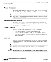
...that supports input voltages between 100 and 240 VAC. You can also connect the Cisco RPS 300 or the Cisco RPS 675 to provide backup power if the switch internal power supply should be connected to the RPS receptacle. 2-16 Catalyst 3750 Switch Hardware Installation... Guide 78-15136-02 Internal Power Supply Connector The internal power supply is powered through the internal power supply. Cisco RPS Connector Specific Cisco RPS modes support specific Catalyst 3750 switches: • Cisco RPS 300 (model PWR300-AC-RPS-N1) supports the Catalyst ...
...that supports input voltages between 100 and 240 VAC. You can also connect the Cisco RPS 300 or the Cisco RPS 675 to provide backup power if the switch internal power supply should be connected to the RPS receptacle. 2-16 Catalyst 3750 Switch Hardware Installation... Guide 78-15136-02 Internal Power Supply Connector The internal power supply is powered through the internal power supply. Cisco RPS Connector Specific Cisco RPS modes support specific Catalyst 3750 switches: • Cisco RPS 300 (model PWR300-AC-RPS-N1) supports the Catalyst ...

Hardware Installation Guide
Page 57
... -DB-25 female DTE adapter. The RPS is a redundant power system that can support six external network devices and provides power to the Cisco RPS 300 Redundant Power System Hardware Installation Guide. For more information on the Cisco RPS 300, refer to one failed device at a time...., preventing loss of network traffic. Chapter 2 Product Overview Rear Panel Description Cisco RPS 675 The RPS is a redundant power system that adapter from Cisco. Console Port You can support six external network devices and provides power to a PC by means of 675W. For more information on page ...
... -DB-25 female DTE adapter. The RPS is a redundant power system that can support six external network devices and provides power to the Cisco RPS 300 Redundant Power System Hardware Installation Guide. For more information on the Cisco RPS 300, refer to one failed device at a time...., preventing loss of network traffic. Chapter 2 Product Overview Rear Panel Description Cisco RPS 675 The RPS is a redundant power system that adapter from Cisco. Console Port You can support six external network devices and provides power to a PC by means of 675W. For more information on page ...

Hardware Installation Guide
Page 61
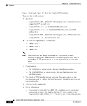
Read the topics and perform the procedures in mind while planning your switch and how to interpret the power-on self-test (POST) that ensures proper operation. CH A P T E R 3 Switch Installation This chapter describes how to start your stack. It describes how to install the ...
Read the topics and perform the procedures in mind while planning your switch and how to interpret the power-on self-test (POST) that ensures proper operation. CH A P T E R 3 Switch Installation This chapter describes how to start your stack. It describes how to install the ...


