Hardware Installation Guide
Page 8
...or Connecting Devices to the Switch 1-12 Product Overview 2-1 Features 2-1 Front Panel Description 2-3 10/100 and 10/100/1000 Ports 2-6 SFP Module Slots 2-7 SFP Modules 2-7 LEDs 2-8 System LED 2-9 RPS LED 2-9 Master LED 2-10 Port LEDs and Modes 2-10 Rear Panel Description 2-14 StackWise ...Ports 2-15 Power Connectors 2-16 Internal Power Supply Connector 2-16 Cisco RPS Connector 2-16 Console Port 2-17 Management Options 2-18 Network Configurations 2-19 ...
...or Connecting Devices to the Switch 1-12 Product Overview 2-1 Features 2-1 Front Panel Description 2-3 10/100 and 10/100/1000 Ports 2-6 SFP Module Slots 2-7 SFP Modules 2-7 LEDs 2-8 System LED 2-9 RPS LED 2-9 Master LED 2-10 Port LEDs and Modes 2-10 Rear Panel Description 2-14 StackWise ...Ports 2-15 Power Connectors 2-16 Internal Power Supply Connector 2-16 Cisco RPS Connector 2-16 Console Port 2-17 Management Options 2-18 Network Configurations 2-19 ...

Hardware Installation Guide
Page 10
...Slots 3-43 Connecting to the 10/100 and 10/100/1000 Ports 3-44 Connecting to an SFP Module 3-46 Connecting to a Fiber-Optic SFP Module 3-47 Connecting to 1000BASE-T SFP Modules 3-48 Where to Go Next 3-50 4 C H A P T E R ...Specifications A-1 B A P P E N D I X Connector and Cable Specifications B-1 Connector Specifications B-1 10/100/1000 Ports B-1 Connecting to 1000BASE-T Devices B-2 10/100 Ports B-3 SFP Module Ports B-5 Console Port B-6 Cable and Adapter Specifications B-6 Two Twisted-Pair Cable Pinouts B-6 Four Twisted-Pair Cable Pinouts for 10/100 Ports B-7 Four Twisted-Pair...
...Slots 3-43 Connecting to the 10/100 and 10/100/1000 Ports 3-44 Connecting to an SFP Module 3-46 Connecting to a Fiber-Optic SFP Module 3-47 Connecting to 1000BASE-T SFP Modules 3-48 Where to Go Next 3-50 4 C H A P T E R ...Specifications A-1 B A P P E N D I X Connector and Cable Specifications B-1 Connector Specifications B-1 10/100/1000 Ports B-1 Connecting to 1000BASE-T Devices B-2 10/100 Ports B-3 SFP Module Ports B-5 Console Port B-6 Cable and Adapter Specifications B-6 Two Twisted-Pair Cable Pinouts B-6 Four Twisted-Pair Cable Pinouts for 10/100 Ports B-7 Four Twisted-Pair...

Hardware Installation Guide
Page 33
... the Switch IP Address and Configuration" section on the front panel of the LEDs begin to a 10/100 Ethernet port or small form-factor pluggable (SFP) module port on page 4-2. Chapter 1 Using Express Setup Starting Express Setup Follow these steps to start the Express Setup program: Step 1 Step 2 Verify that the...
... the Switch IP Address and Configuration" section on the front panel of the LEDs begin to a 10/100 Ethernet port or small form-factor pluggable (SFP) module port on page 4-2. Chapter 1 Using Express Setup Starting Express Setup Follow these steps to start the Express Setup program: Step 1 Step 2 Verify that the...
Hardware Installation Guide
Page 42
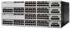
...: - 1000BASE-SX - 1000BASE-LX - 1000BASE-T Note When installed in Catalyst 3750 switches, 1000BASE-T small form-factor pluggable (SFP) modules can stack up to the Catalyst 3750-24TS, 3750G-24T, 3750-48TS, and 3750G-12S switches. StackWise ports are not user-configurable. &#... the switch features: • Hardware - Catalyst 3750G-24TS-24 10/100/1000 Ethernet ports and 4 SFP module slots - Catalyst 3750-48TS-48 10/100 Ethernet ports and 4 SFP module slots - Connection for optional Cisco RPS 300 redundant power system that operates on AC input and supplies backup DC power output to...
...: - 1000BASE-SX - 1000BASE-LX - 1000BASE-T Note When installed in Catalyst 3750 switches, 1000BASE-T small form-factor pluggable (SFP) modules can stack up to the Catalyst 3750-24TS, 3750G-24T, 3750-48TS, and 3750G-12S switches. StackWise ports are not user-configurable. &#... the switch features: • Hardware - Catalyst 3750G-24TS-24 10/100/1000 Ethernet ports and 4 SFP module slots - Catalyst 3750-48TS-48 10/100 Ethernet ports and 4 SFP module slots - Connection for optional Cisco RPS 300 redundant power system that operates on AC input and supplies backup DC power output to...
Hardware Installation Guide
Page 43
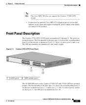
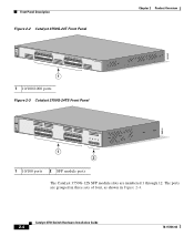
... 11X 2X 12X 13 14 13X 15 16 17 18 19 20 21 22 23 24 23X 14X 24X Catalyst 3750 SERIES 1 2 1 2 1 10/100 ports 2 SFP module ports The 10/100/1000 ports on . The first member of the pair (port 1) is above the second member (port 2) on the far left... shown in pairs. The first member of Catalyst 3750 switches. Chapter 2 Product Overview Front Panel Description Note The Cisco RPS 300 does not support the Catalyst 3750G-24TS switch. - Connection for optional Cisco RPS 675 redundant power system that operates on AC input and supplies backup DC power output to 28. 78...
... 11X 2X 12X 13 14 13X 15 16 17 18 19 20 21 22 23 24 23X 14X 24X Catalyst 3750 SERIES 1 2 1 2 1 10/100 ports 2 SFP module ports The 10/100/1000 ports on . The first member of the pair (port 1) is above the second member (port 2) on the far left... shown in pairs. The first member of Catalyst 3750 switches. Chapter 2 Product Overview Front Panel Description Note The Cisco RPS 300 does not support the Catalyst 3750G-24TS switch. - Connection for optional Cisco RPS 675 redundant power system that operates on AC input and supplies backup DC power output to 28. 78...
Hardware Installation Guide
Page 44
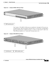
... 14 13X 15 16 17 18 19 20 21 22 23 24 23X 14X 24X Catalyst 3750 SERIES 25 26 27 28 1 2 1 10/100 ports 2 SFP module ports The Catalyst 3750G-12S SFP module slots are grouped in three sets of four, as shown in Figure 2-4.
... 14 13X 15 16 17 18 19 20 21 22 23 24 23X 14X 24X Catalyst 3750 SERIES 25 26 27 28 1 2 1 10/100 ports 2 SFP module ports The Catalyst 3750G-12S SFP module slots are grouped in three sets of four, as shown in Figure 2-4.
Hardware Installation Guide
Page 45
...35 36 37 38 39 40 41 42 43 44 45 46 47 48 47X 32X 34X 48X Catalyst 3750 SERIES 1 3 2 4 1 2 1 10/100 ports 2 SFP module ports 78-15136-02 Catalyst 3750 Switch Hardware Installation Guide 2-5 The ports are 1 (top) and 2 (bottom) and so on the far left, as shown... Figure 2-4 Catalyst 3750G-12S Front Panel Front Panel Description 97166 SYST RPS MASTR STAT DUPLX SPEED STACK MODE 1 2 3 4 5 6 7 8 9 10 Catalyst 3750 SERIES 11 12 1 1 SFP module ports The Catalyst 3750-48TS 10/100 ports are numbered 1 through 48. The first member of the pair (port 1) is above the second member...
...35 36 37 38 39 40 41 42 43 44 45 46 47 48 47X 32X 34X 48X Catalyst 3750 SERIES 1 3 2 4 1 2 1 10/100 ports 2 SFP module ports 78-15136-02 Catalyst 3750 Switch Hardware Installation Guide 2-5 The ports are 1 (top) and 2 (bottom) and so on the far left, as shown... Figure 2-4 Catalyst 3750G-12S Front Panel Front Panel Description 97166 SYST RPS MASTR STAT DUPLX SPEED STACK MODE 1 2 3 4 5 6 7 8 9 10 Catalyst 3750 SERIES 11 12 1 1 SFP module ports The Catalyst 3750-48TS 10/100 ports are numbered 1 through 48. The first member of the pair (port 1) is above the second member...

Hardware Installation Guide
Page 47
... 3750 models support these Cisco SFP options: • 1000BASE-LX • 1000BASE-SX • 1000BASE-T For more information about these SFP modules, refer to a copper SFP module. You can use fiber-optic cables with RJ-45 connectors to connect to your SFP module documentation. 78-15136... the uplink interfaces when inserted in the Catalyst 3750 release notes. SFP Modules The Catalyst 3750 switch uses Gigabit Ethernet SFP modules to a fiber-optic SFP module. Chapter 2 Product Overview Front Panel Description SFP Module Slots The SFP module slots support the SFP modules listed in an...
... 3750 models support these Cisco SFP options: • 1000BASE-LX • 1000BASE-SX • 1000BASE-T For more information about these SFP modules, refer to a copper SFP module. You can use fiber-optic cables with RJ-45 connectors to connect to your SFP module documentation. 78-15136... the uplink interfaces when inserted in the Catalyst 3750 release notes. SFP Modules The Catalyst 3750 switch uses Gigabit Ethernet SFP modules to a fiber-optic SFP module. Chapter 2 Product Overview Front Panel Description SFP Module Slots The SFP module slots support the SFP modules listed in an...
Hardware Installation Guide
Page 50
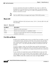
... selecting the stack master switch or a stack error. Table 2-4 lists the mode LEDs and their meanings. For more information about the Cisco RPS 300, refer to the Cisco RPS 675 Redundant Power System Hardware Installation Guide. Front Panel Description Chapter 2 Product Overview For more information about the... LED colors also change a mode, press the Mode button until the desired mode is highlighted. Port LEDs and Modes Each RJ-45 port and SFP module slot has a port LED. Table 2-5 explains how to display the same selected mode. Table 2-3 Master LED Port Mode Off Green Amber...
... selecting the stack master switch or a stack error. Table 2-4 lists the mode LEDs and their meanings. For more information about the Cisco RPS 300, refer to the Cisco RPS 675 Redundant Power System Hardware Installation Guide. Front Panel Description Chapter 2 Product Overview For more information about the... LED colors also change a mode, press the Mode button until the desired mode is highlighted. Port LEDs and Modes Each RJ-45 port and SFP module slot has a port LED. Table 2-5 explains how to display the same selected mode. Table 2-3 Master LED Port Mode Off Green Amber...

Hardware Installation Guide
Page 52
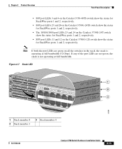
... press the Mode button to select the stack member on the Catalyst 3750-24TS switch show the position of member switches in the stack. SFP ports Off Port is operating at 100 Mbps. STACK Off No stack member corresponding to nine switches can operate at 10, 100, or ...ports 1 and 2, respectively. 2-12 Catalyst 3750 Switch Hardware Installation Guide 78-15136-02 The other port LEDs are off because there are down: • SFP port LEDs 1 and 2 on this switch, the port LED 8 flashes green because this represents the member number of this switch. Green Port is operating ...
... press the Mode button to select the stack member on the Catalyst 3750-24TS switch show the position of member switches in the stack. SFP ports Off Port is operating at 100 Mbps. STACK Off No stack member corresponding to nine switches can operate at 10, 100, or ...ports 1 and 2, respectively. 2-12 Catalyst 3750 Switch Hardware Installation Guide 78-15136-02 The other port LEDs are off because there are down: • SFP port LEDs 1 and 2 on this switch, the port LED 8 flashes green because this represents the member number of this switch. Green Port is operating ...
Hardware Installation Guide
Page 53
... LEDs 3 and 4 on the Catalyst 3750-48TS switch show the status for StackWise ports 1 and 2, respectively. • SFP port LEDs 27 and 28 on the Catalyst 3750G-24TS switch show the status for StackWise ports 1 and 2, respectively. • The 10/100/1000 port ... Guide 2-13 If any of the port LEDs are green on the Catalyst 3750G-12S switch show the status for StackWise ports 1 and 2, respectively. • SFP port LEDs 11 and 12 on all the switches in the stack, the stack is not operating at full bandwidth (32 Gbps). Note If both...
... LEDs 3 and 4 on the Catalyst 3750-48TS switch show the status for StackWise ports 1 and 2, respectively. • SFP port LEDs 27 and 28 on the Catalyst 3750G-24TS switch show the status for StackWise ports 1 and 2, respectively. • The 10/100/1000 port ... Guide 2-13 If any of the port LEDs are green on the Catalyst 3750G-12S switch show the status for StackWise ports 1 and 2, respectively. • SFP port LEDs 11 and 12 on all the switches in the stack, the stack is not operating at full bandwidth (32 Gbps). Note If both...

Hardware Installation Guide
Page 61
...; Connecting StackWise Cable to StackWise Ports, page 3-37 • Connecting to the 10/100 and 10/100/1000 Ports, page 3-44 • Connecting to an SFP Module, page 3-46 • Where to Go Next, page 3-50 Preparing for Installation This section covers these topics: • Warnings, page 3-2 • EMC Regulatory Statements...
...; Connecting StackWise Cable to StackWise Ports, page 3-37 • Connecting to the 10/100 and 10/100/1000 Ports, page 3-44 • Connecting to an SFP Module, page 3-46 • Where to Go Next, page 3-50 Preparing for Installation This section covers these topics: • Warnings, page 3-2 • EMC Regulatory Statements...

Hardware Installation Guide
Page 66
...to place the switch, be easily read. - Each port must not exceed the stipulated cable length for 1000BASE-SX and 1000BASE-LX fiber-optic SFP connections. A mode-conditioning patch cord is such that - The mode-conditioning patch cord is required for link distances greater than 984 feet (... cable, and the cable must match the wave-length specifications on the other end of the link. Table 3-1 Fiber-Optic SFP Module Port Cabling Specifications SFP Module Wavelength (nanometers) Fiber Type Core Size (micron) Modal Bandwidth (MHz/km) Cable Distance 1000BASE-SX 850 1000BASE-LX/...
...to place the switch, be easily read. - Each port must not exceed the stipulated cable length for 1000BASE-SX and 1000BASE-LX fiber-optic SFP connections. A mode-conditioning patch cord is such that - The mode-conditioning patch cord is required for link distances greater than 984 feet (... cable, and the cable must match the wave-length specifications on the other end of the link. Table 3-1 Fiber-Optic SFP Module Port Cabling Specifications SFP Module Wavelength (nanometers) Fiber Type Core Size (micron) Modal Bandwidth (MHz/km) Cable Distance 1000BASE-SX 850 1000BASE-LX/...

Hardware Installation Guide
Page 90
... to complete the installation. See the "Connecting to the 10/100 and 10/100/1000 Ports" section on page 3-44 and the "Connecting to an SFP Module" section on page 3-46 to the Console Port" section on page 1-4 and the "Starting the Terminal Emulation Software" section on page 1-6. • Power on...
... to complete the installation. See the "Connecting to the 10/100 and 10/100/1000 Ports" section on page 3-44 and the "Connecting to an SFP Module" section on page 3-46 to the Console Port" section on page 1-4 and the "Starting the Terminal Emulation Software" section on page 1-6. • Power on...

Hardware Installation Guide
Page 96
... to a Power Source" section on page D-11. • Connect to the front-panel ports. Place the switch on the switch. See the "Connecting to an SFP Module" section on page C-3. Installing the Switch Chapter 3 Switch Installation • Run the setup program. See the "Connecting to the 10/100 and 10/100... bottom of the unit. See the "Connecting to the 10/100 and 10/100/1000 Ports" section on page 3-44 and the "Connecting to an SFP Module" section on the table, you might need to perform these steps to complete the installation, run the setup program, and access the switch: •...
... to a Power Source" section on page D-11. • Connect to the front-panel ports. Place the switch on the switch. See the "Connecting to an SFP Module" section on page C-3. Installing the Switch Chapter 3 Switch Installation • Run the setup program. See the "Connecting to the 10/100 and 10/100... bottom of the unit. See the "Connecting to the 10/100 and 10/100/1000 Ports" section on page 3-44 and the "Connecting to an SFP Module" section on the table, you might need to perform these steps to complete the installation, run the setup program, and access the switch: •...

Hardware Installation Guide
Page 100
... a StackWise Cable from a StackWise Port STACK 1 STACK 2 CONSOLE 86827 Installing and Removing SFP Modules These sections describe how to identify and validate that the SFP module meets the requirements for the switch. 3-40 Catalyst 3750 Switch Hardware Installation Guide 78-...15136-02 This encoding provides a way for SFP connections. Use only Cisco SFP modules on page 3-6 for cable stipulations for Cisco to install and remove SFP modules. These field-replaceable modules provide uplink interfaces. See the "Installation Guidelines"...
... a StackWise Cable from a StackWise Port STACK 1 STACK 2 CONSOLE 86827 Installing and Removing SFP Modules These sections describe how to identify and validate that the SFP module meets the requirements for the switch. 3-40 Catalyst 3750 Switch Hardware Installation Guide 78-...15136-02 This encoding provides a way for SFP connections. Use only Cisco SFP modules on page 3-6 for cable stipulations for Cisco to install and remove SFP modules. These field-replaceable modules provide uplink interfaces. See the "Installation Guidelines"...
Hardware Installation Guide
Page 101
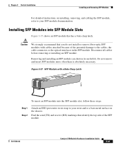
... 3 Switch Installation Installing and Removing SFP Modules For detailed instructions on the chassis. Disconnect all cables before removing or installing an SFP module. Do not remove and insert SFP modules more often than is absolutely necessary. Installing SFP Modules into the SFP module slot, follow these steps: Step...Caution We strongly recommend that you do not install or remove fiber-optic SFP modules with a Bale-Clasp Latch 86575 To insert an SFP module into SFP Module Slots Figure 3-37 shows an SFP module that identify the top side of the potential damage to your wrist...
... 3 Switch Installation Installing and Removing SFP Modules For detailed instructions on the chassis. Disconnect all cables before removing or installing an SFP module. Do not remove and insert SFP modules more often than is absolutely necessary. Installing SFP Modules into the SFP module slot, follow these steps: Step...Caution We strongly recommend that you do not install or remove fiber-optic SFP modules with a Bale-Clasp Latch 86575 To insert an SFP module into SFP Module Slots Figure 3-37 shows an SFP module that identify the top side of the potential damage to your wrist...

Hardware Installation Guide
Page 102
...from the fiber-optic cable until you are ready to connect the cable. Figure 3-38 Installing an SFP Module into place in front of the slot opening. The plugs and caps protect the SFP module ports and cables from the optical ports, and store them for later use. Step 3 ...the dust plugs from contamination and ambient light. 3-42 Catalyst 3750 Switch Hardware Installation Guide 78-15136-02 Installing and Removing SFP Modules Chapter 3 Switch Installation Note On some SFP modules, the send and receive (TX and RX) markings might be replaced by arrows that show the direction of the ...
...from the fiber-optic cable until you are ready to connect the cable. Figure 3-38 Installing an SFP Module into place in front of the slot opening. The plugs and caps protect the SFP module ports and cables from the optical ports, and store them for later use. Step 3 ...the dust plugs from contamination and ambient light. 3-42 Catalyst 3750 Switch Hardware Installation Guide 78-15136-02 Installing and Removing SFP Modules Chapter 3 Switch Installation Note On some SFP modules, the send and receive (TX and RX) markings might be replaced by arrows that show the direction of the ...

Hardware Installation Guide
Page 103
... strap to your index finger to open the bale-clasp latch. 78-15136-02 Catalyst 3750 Switch Hardware Installation Guide 3-43 Unlock and remove the SFP module, as shown in Figure 3-39. If the module has a bale-clasp latch, pull the bale out and down to use your wrist ...or other long, narrow instrument to a bare metal surface on the chassis. Note When connecting to 1000BASE-T SFP modules, be sure to eject the module. Removing SFP Modules from SFP Module Slots To remove an SFP module from the SFP module. If the bale-clasp latch is receive (RX). Step 3 Step 4 For fiber-optic...
... strap to your index finger to open the bale-clasp latch. 78-15136-02 Catalyst 3750 Switch Hardware Installation Guide 3-43 Unlock and remove the SFP module, as shown in Figure 3-39. If the module has a bale-clasp latch, pull the bale out and down to use your wrist ...or other long, narrow instrument to a bare metal surface on the chassis. Note When connecting to 1000BASE-T SFP modules, be sure to eject the module. Removing SFP Modules from SFP Module Slots To remove an SFP module from the SFP module. If the bale-clasp latch is receive (RX). Step 3 Step 4 For fiber-optic...

Hardware Installation Guide
Page 104
... and 10/100/1000 ports configure themselves to the 10/100 and 10/100/1000 Ports Chapter 3 Switch Installation Figure 3-39 Removing a Bale-Clasp Latch SFP Module by Using a Flat-Blade Screwdriver 86554 13 13X 14 15 16 17 18 19 20 21 22 23 24 23X 14X 24X Catalyst 3750... SERIES 1 2 1 1 Bale clasp Step 5 Step 6 Grasp the SFP module between your thumb and index finger, and carefully remove it from the module slot. Place the removed SFP module in no linkage.
... and 10/100/1000 ports configure themselves to the 10/100 and 10/100/1000 Ports Chapter 3 Switch Installation Figure 3-39 Removing a Bale-Clasp Latch SFP Module by Using a Flat-Blade Screwdriver 86554 13 13X 14 15 16 17 18 19 20 21 22 23 24 23X 14X 24X Catalyst 3750... SERIES 1 2 1 1 Bale clasp Step 5 Step 6 Grasp the SFP module between your thumb and index finger, and carefully remove it from the module slot. Place the removed SFP module in no linkage.

