

Installation Guide
Page 3
... and Features 1-4 Front Panel LEDs 1-5 Chassis Cooling 1-6 Power Supplies 1-7 Environmental Monitoring of the Power Supplies 1-8 Power Management for the Catalyst 4900M Switch 1-8 Power Management Modes 1-8 Catalyst 4900M Half-Card Modules 1-8 WS-X4920-GB-RJ45 Half-Card Ethernet Module 1-9 WS-X4904-10GE Half-Card Ethernet Module 1-10 WS-X4908-10GE Half-Card Ethernet Module 1-11 WS-X4908-10G-RJ45 Half-Card Ethernet Module...
... and Features 1-4 Front Panel LEDs 1-5 Chassis Cooling 1-6 Power Supplies 1-7 Environmental Monitoring of the Power Supplies 1-8 Power Management for the Catalyst 4900M Switch 1-8 Power Management Modes 1-8 Catalyst 4900M Half-Card Modules 1-8 WS-X4920-GB-RJ45 Half-Card Ethernet Module 1-9 WS-X4904-10GE Half-Card Ethernet Module 1-10 WS-X4908-10GE Half-Card Ethernet Module 1-11 WS-X4908-10G-RJ45 Half-Card Ethernet Module...
Installation Guide
Page 4
...14 Installing Switching Modules 3-16 Removing and Replacing the Power Supply 3-18 Required Tools 3-18 Removing a Power Supply 3-18 Installing a Power Supply 3-19 Removing and Replacing the Fan Assembly 3-20 ...Required Tools 3-20 Removing the Fan Assembly 3-20 Installing the Fan Assembly 3-21 Verifying the Installation 3-21 4 C H A P T E R Troubleshooting the Installation 4-1 Getting Started 4-1 Problem Solving to the System Component Level 4-2 Identifying Startup Problems 4-2 LED Readings 4-2 Cisco...
...14 Installing Switching Modules 3-16 Removing and Replacing the Power Supply 3-18 Required Tools 3-18 Removing a Power Supply 3-18 Installing a Power Supply 3-19 Removing and Replacing the Fan Assembly 3-20 ...Required Tools 3-20 Removing the Fan Assembly 3-20 Installing the Fan Assembly 3-21 Verifying the Installation 3-21 4 C H A P T E R Troubleshooting the Installation 4-1 Getting Started 4-1 Problem Solving to the System Component Level 4-2 Identifying Startup Problems 4-2 LED Readings 4-2 Cisco...

Installation Guide
Page 5
... into Laser Beam B-13 Statement 1017-Restricted Area B-14 Statement 1019-Main Disconnecting Device B-16 Statement 1024-Ground Conductor B-17 Statement 1028-More Than One Power Supply B-20 Statement 1029-Blank Faceplates and Cover Panels B-22 Statement 1030-Equipment Installation B-25 Statement 1040-Product Disposal B-27 Statement 1045-Short-circuit Protection B-28...B-40 Statement 6004-EU Battery Disposal and Recycling B-40 Statement 6005-California Perchlorate Contamination Prevention Act (Title 22, California Code of Regulations, Chapter 33) B-40 Cisco Catalyst 4900M Switch Installation Guide v
... into Laser Beam B-13 Statement 1017-Restricted Area B-14 Statement 1019-Main Disconnecting Device B-16 Statement 1024-Ground Conductor B-17 Statement 1028-More Than One Power Supply B-20 Statement 1029-Blank Faceplates and Cover Panels B-22 Statement 1030-Equipment Installation B-25 Statement 1040-Product Disposal B-27 Statement 1045-Short-circuit Protection B-28...B-40 Statement 6004-EU Battery Disposal and Recycling B-40 Statement 6005-California Perchlorate Contamination Prevention Act (Title 22, California Code of Regulations, Chapter 33) B-40 Cisco Catalyst 4900M Switch Installation Guide v

Installation Guide
Page 17
...GB or 10-GB ports and two half-card Ethernet module slots that can accommodate a several different styles of the chassis. 78-18350-02 Cisco Catalyst 4900M Switch Installation Guide 1-1 The chapter contains these sections: • Catalyst 4900M Switch Chassis, page 1-1 • Catalyst 4900M Half-... RU horizontal high-performance dedicated Ethernet switch. The switch has one removable variable-speed fan tray and supports redundant power supplies. Product Overview 1 C H A P T E R Revised: January 4, 2012 This chapter describes the Catalyst 4900M switch and the supported half-card ...
...GB or 10-GB ports and two half-card Ethernet module slots that can accommodate a several different styles of the chassis. 78-18350-02 Cisco Catalyst 4900M Switch Installation Guide 1-1 The chapter contains these sections: • Catalyst 4900M Switch Chassis, page 1-1 • Catalyst 4900M Half-... RU horizontal high-performance dedicated Ethernet switch. The switch has one removable variable-speed fan tray and supports redundant power supplies. Product Overview 1 C H A P T E R Revised: January 4, 2012 This chapter describes the Catalyst 4900M switch and the supported half-card ...

Installation Guide
Page 19
...; The Catalyst 4900M switch chassis is available as part of the accessory kit. Field replaceable. 1000 W AC-input and 1000 W DC-input power supplies are triggered at 49°C (120.2°F) generating a minor alarm and at 67°C (152.6°F). -40° to 167°...15.4 kg) (max) 151.7 CFM (max) 78-18350-02 Cisco Catalyst 4900M Switch Installation Guide 1-3 Chapter 1 Product Overview Catalyst 4900M Switch Chassis Table 1-1 Catalyst 4900M Switch Features (continued) Feature Reset switch Fan tray Power supplies Description The Reset button is not provided as an option. Variable-...
...; The Catalyst 4900M switch chassis is available as part of the accessory kit. Field replaceable. 1000 W AC-input and 1000 W DC-input power supplies are triggered at 49°C (120.2°F) generating a minor alarm and at 67°C (152.6°F). -40° to 167°...15.4 kg) (max) 151.7 CFM (max) 78-18350-02 Cisco Catalyst 4900M Switch Installation Guide 1-3 Chapter 1 Product Overview Catalyst 4900M Switch Chassis Table 1-1 Catalyst 4900M Switch Features (continued) Feature Reset switch Fan tray Power supplies Description The Reset button is not provided as an option. Variable-...
Installation Guide
Page 20
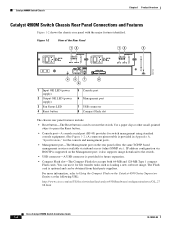
...such as loading a new software image. Figure 1-2 View of the Rear Panel 12 12 3 232122 45 7 8 6 1 Input OK LED (power supply) 2 Output OK LED (power supply) 3 Fan Status LED 4 Reset button 5 Console port 6 Management port 7 USB connector 8 Compact Flash slot The chassis rear panel features include...is supported on the Catalyst 4500 Series Supervisor Engines at the following URL: http://www.cisco.com/en/US/docs/switches/lan/catalyst4500/hardware/configuration/notes/OL_27 88.html Cisco Catalyst 4900M Switch Installation Guide 1-4 78-18350-02 For more information, refer to restart ...
...such as loading a new software image. Figure 1-2 View of the Rear Panel 12 12 3 232122 45 7 8 6 1 Input OK LED (power supply) 2 Output OK LED (power supply) 3 Fan Status LED 4 Reset button 5 Console port 6 Management port 7 USB connector 8 Compact Flash slot The chassis rear panel features include...is supported on the Catalyst 4500 Series Supervisor Engines at the following URL: http://www.cisco.com/en/US/docs/switches/lan/catalyst4500/hardware/configuration/notes/OL_27 88.html Cisco Catalyst 4900M Switch Installation Guide 1-4 78-18350-02 For more information, refer to restart ...
Installation Guide
Page 21
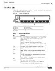
... other than an individual port test fails • Off-System is in rommon mode or a power supply has failed Switch is disabled • Green-10/100 BASE-T console port is in link-down state or not connected. Cisco Catalyst 4900M Switch Installation Guide 1-5 Table 1-3 lists the front panel LEDS and their meanings. Chapter...-Port is operational. • Yellow-Port is in link-up state. • Off-10/100/1000BASE-T Management port is disabled by user. • Flashing yellow-Power-on the chassis front panel (see Figure 1-3) provide visual status for the switch.
... other than an individual port test fails • Off-System is in rommon mode or a power supply has failed Switch is disabled • Green-10/100 BASE-T console port is in link-down state or not connected. Cisco Catalyst 4900M Switch Installation Guide 1-5 Table 1-3 lists the front panel LEDS and their meanings. Chapter...-Port is operational. • Yellow-Port is in link-up state. • Off-10/100/1000BASE-T Management port is disabled by user. • Flashing yellow-Power-on the chassis front panel (see Figure 1-3) provide visual status for the switch.
Installation Guide
Page 22
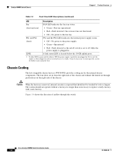
...status using the CLI. If either LED is green and the other is OFF the power supply is probably not plugged in and not switched on or it is red, the supply is either plugged in . Cisco Catalyst 4900M Switch Installation Guide 1-6 78-18350-02 If it is plugged in from the...Cooling The hot-swappable chassis fan tray (WS-X4992) provides cooling air for longer than is located below the 10-GB uplink ports. 1. PS1 and PS2 PS1 and the PS2 LEDs indicates the internal power supply status. (front) • Off-No power to off while the power supply is faulty. Figure 1-4 shows the direction...
...status using the CLI. If either LED is green and the other is OFF the power supply is probably not plugged in and not switched on or it is red, the supply is either plugged in . Cisco Catalyst 4900M Switch Installation Guide 1-6 78-18350-02 If it is plugged in from the...Cooling The hot-swappable chassis fan tray (WS-X4992) provides cooling air for longer than is located below the 10-GB uplink ports. 1. PS1 and PS2 PS1 and the PS2 LEDs indicates the internal power supply status. (front) • Off-No power to off while the power supply is faulty. Figure 1-4 shows the direction...

Installation Guide
Page 23
... Overview Figure 1-4 Catalyst 4900M Chassis Airflow Catalyst 4900M Switch Chassis 232124 There are also LEDs on the power supplies that you always connect both power supplies to separate AC or DC circuits for optimal power reliability. 78-18350-02 Cisco Catalyst 4900M Switch Installation Guide 1-7 Sensors monitor the internal air temperatures. The switch starts with only...
... Overview Figure 1-4 Catalyst 4900M Chassis Airflow Catalyst 4900M Switch Chassis 232124 There are also LEDs on the power supplies that you always connect both power supplies to separate AC or DC circuits for optimal power reliability. 78-18350-02 Cisco Catalyst 4900M Switch Installation Guide 1-7 Sensors monitor the internal air temperatures. The switch starts with only...

Installation Guide
Page 24
...-Card Ethernet Module, page 1-9 • WS-X4904-10GE Half-Card Ethernet Module, page 1-10 • WS-X4908-10GE Half-Card Ethernet Module, page 1-11 • WS-X4908-10G-RJ45 Half-Card Ethernet Module, page 1-13 The half-card modules can maintain normal system operation by a running system regardless of the power supply and reports status through the...
...-Card Ethernet Module, page 1-9 • WS-X4904-10GE Half-Card Ethernet Module, page 1-10 • WS-X4908-10GE Half-Card Ethernet Module, page 1-11 • WS-X4908-10G-RJ45 Half-Card Ethernet Module, page 1-13 The half-card modules can maintain normal system operation by a running system regardless of the power supply and reports status through the...

Installation Guide
Page 33
... for sizing the air-conditioning requirements for an installation. When planning the location of the AC power cords. Table 2-1 1000 W AC-Input Power Supply Power Cords Locale Power Cord Part Number Argentina CAB-IR2073-C15-AR= (was CAB-7KACR=) Australia, New Zealand CAB...Figure 2-4 NEMA 5-151 13 A, 125 VAC Figure 2-5 78-18350-02 Cisco Catalyst 4900M Switch Installation Guide 2-3 When wires are available for the 1000 W AC-input power supply. Chapter 2 Site Planning Site Power Requirements Warning Ultimate disposal of this product should be useful for planning the...
... for sizing the air-conditioning requirements for an installation. When planning the location of the AC power cords. Table 2-1 1000 W AC-Input Power Supply Power Cords Locale Power Cord Part Number Argentina CAB-IR2073-C15-AR= (was CAB-7KACR=) Australia, New Zealand CAB...Figure 2-4 NEMA 5-151 13 A, 125 VAC Figure 2-5 78-18350-02 Cisco Catalyst 4900M Switch Installation Guide 2-3 When wires are available for the 1000 W AC-input power supply. Chapter 2 Site Planning Site Power Requirements Warning Ultimate disposal of this product should be useful for planning the...
Installation Guide
Page 38
Statement 1024 Note To completely de-energize the system, unplug the power cord. • Always use caution when lifting heavy equipment. • Always turn all power supplies off by unplugging all power and external cables before installing or removing a chassis. • Keep the chassis area clear and free of dust during and after installation. •... electrician if you are uncertain that could get caught in compliance with any action that creates a potential hazard to install, replace, or service this equipment. Cisco Catalyst 4900M Switch Installation Guide 2-8 78-18350-02
Statement 1024 Note To completely de-energize the system, unplug the power cord. • Always use caution when lifting heavy equipment. • Always turn all power supplies off by unplugging all power and external cables before installing or removing a chassis. • Keep the chassis area clear and free of dust during and after installation. •... electrician if you are uncertain that could get caught in compliance with any action that creates a potential hazard to install, replace, or service this equipment. Cisco Catalyst 4900M Switch Installation Guide 2-8 78-18350-02

Installation Guide
Page 39
...damage. ESD wrist strap connector - Completing each activity helps to the equipment Dedicated (separate) circuits for redundant power supplies UPS for power failures 78-18350-02 Cisco Catalyst 4900M Switch Installation Guide 2-9 The wrist strap protects only the card from ESD voltages on clothing can ...layout Floor covering Shock and vibration Lighting Maintenance access 2 Environmental evaluation: Ambient temperature Humidity Altitude Atmospheric contamination Airflow 3 Power evaluation: Input power type Receptacle proximity to ensure a successful switch installation.
...damage. ESD wrist strap connector - Completing each activity helps to the equipment Dedicated (separate) circuits for redundant power supplies UPS for power failures 78-18350-02 Cisco Catalyst 4900M Switch Installation Guide 2-9 The wrist strap protects only the card from ESD voltages on clothing can ...layout Floor covering Shock and vibration Lighting Maintenance access 2 Environmental evaluation: Ambient temperature Humidity Altitude Atmospheric contamination Airflow 3 Power evaluation: Input power type Receptacle proximity to ensure a successful switch installation.

Installation Guide
Page 43
...prevent airflow restriction, allow at or near the bottom of a rack may generate excessive heat that you lift. 78-18350-02 Cisco Catalyst 4900M Switch Installation Guide 3-3 Route cables away from other equipment will not obstruct the airflow through the chassis or impair access... these guidelines: • Ensure that equipment near the top of the chassis between your body as you bolt the rack to the power supplies or switching modules. Lifting the Chassis Safely The chassis is properly ventilated. - For physical specifications, see Appendix A, "Specifications." - ...
...prevent airflow restriction, allow at or near the bottom of a rack may generate excessive heat that you lift. 78-18350-02 Cisco Catalyst 4900M Switch Installation Guide 3-3 Route cables away from other equipment will not obstruct the airflow through the chassis or impair access... these guidelines: • Ensure that equipment near the top of the chassis between your body as you bolt the rack to the power supplies or switching modules. Lifting the Chassis Safely The chassis is properly ventilated. - For physical specifications, see Appendix A, "Specifications." - ...

Installation Guide
Page 47
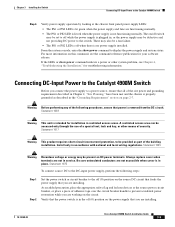
... 4900M Switch Follow these steps and warnings when connecting power to the Catalyst 4900M switch: Step 1 Prior to connecting the power supply to a power source, ensure that all of the site power and grounding requirements described in Chapter 2, "Site Planning...," have been met and the chassis is shown in the "Grounding Requirements" section on page 3-7. The grounding pad for the switch is properly grounded as described in Figure 3-4. 78-18350-02 Cisco...
... 4900M Switch Follow these steps and warnings when connecting power to the Catalyst 4900M switch: Step 1 Prior to connecting the power supply to a power source, ensure that all of the site power and grounding requirements described in Chapter 2, "Site Planning...," have been met and the chassis is shown in the "Grounding Requirements" section on page 3-7. The grounding pad for the switch is properly grounded as described in Figure 3-4. 78-18350-02 Cisco...

Installation Guide
Page 48
... lit green when the measured DC output from the power supply is within operating limits. Cisco Catalyst 4900M Switch Installation Guide 3-8 78-18350-02 Refer to an AC power source. Statement 1019 Step 2 Plug the power cords into the power supplies. Turn the power switches to the ON position. Connecting Power to the Catalyst 4900M Switch Figure 3-4 Grounding Pad...
... lit green when the measured DC output from the power supply is within operating limits. Cisco Catalyst 4900M Switch Installation Guide 3-8 78-18350-02 Refer to an AC power source. Statement 1019 Step 2 Plug the power cords into the power supplies. Turn the power switches to the ON position. Connecting Power to the Catalyst 4900M Switch Figure 3-4 Grounding Pad...
Installation Guide
Page 49
... position on the source DC circuit that feeds the power supply that you are working on DC power terminals. Connecting DC-Input Power to the Catalyst 4900M Switch Before you are installing. 78-18350-02 Cisco Catalyst 4900M Switch Installation Guide 3-9 Warning Before performing any...circuit. Install only in service. Verify that the power switch is no power supply installed. Chapter 3 Installing the Switch Connecting DC-Input Power to the Catalyst 4900M Switch Step 6 Verify power supply operation by looking at the source power circuit breaker, or place a piece of adhesive...
... position on the source DC circuit that feeds the power supply that you are working on DC power terminals. Connecting DC-Input Power to the Catalyst 4900M Switch Before you are installing. 78-18350-02 Cisco Catalyst 4900M Switch Installation Guide 3-9 Warning Before performing any...circuit. Install only in service. Verify that the power switch is no power supply installed. Chapter 3 Installing the Switch Connecting DC-Input Power to the Catalyst 4900M Switch Step 6 Verify power supply operation by looking at the source power circuit breaker, or place a piece of adhesive...

Installation Guide
Page 50
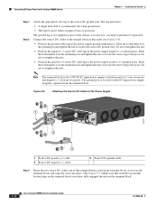
... separately. The lugs must have: • Two holes with 0.62 ±0.02-inch spacing between the hole centers to accommodate the power supply terminal posts. • A 90-degree bend in the barrel to allow the source DC cables to exit the terminal block. • Suitable ...on the terminal block cover to release the cover from the power supply ground terminal. Set the nuts and lockwashers aside. For 6 AWG-sized cable-Panduit LCD6-14AF-L 3-10 Cisco Catalyst 4900M Switch Installation Guide 78-18350-02 Connecting DC-Input Power to the Catalyst 4900M Switch Chapter 3 Installing the Switch ...
... separately. The lugs must have: • Two holes with 0.62 ±0.02-inch spacing between the hole centers to accommodate the power supply terminal posts. • A 90-degree bend in the barrel to allow the source DC cables to exit the terminal block. • Suitable ...on the terminal block cover to release the cover from the power supply ground terminal. Set the nuts and lockwashers aside. For 6 AWG-sized cable-Panduit LCD6-14AF-L 3-10 Cisco Catalyst 4900M Switch Installation Guide 78-18350-02 Connecting DC-Input Power to the Catalyst 4900M Switch Chapter 3 Installing the Switch ...
Installation Guide
Page 52
... necessary. Connecting DC-Input Power to the Catalyst 4900M Switch Chapter 3 Installing the Switch Step 7 Step 8 Attach the appropriate size lug to the posts. The ground lug is located on the terminal block. 3-12 Cisco Catalyst 4900M Switch Installation Guide 78-18350-02 Slide the ...See Figure 3-9.) Make sure that both the top and the bottom clips on the terminal block cover have : • A single hole able to the power supply positive (+) terminal posts. Do not overtighten the nuts. • Position the positive (+) source DC cable lug to accommodate the 4 mm ground post. ...
... necessary. Connecting DC-Input Power to the Catalyst 4900M Switch Chapter 3 Installing the Switch Step 7 Step 8 Attach the appropriate size lug to the posts. The ground lug is located on the terminal block. 3-12 Cisco Catalyst 4900M Switch Installation Guide 78-18350-02 Slide the ...See Figure 3-9.) Make sure that both the top and the bottom clips on the terminal block cover have : • A single hole able to the power supply positive (+) terminal posts. Do not overtighten the nuts. • Position the positive (+) source DC cable lug to accommodate the 4 mm ground post. ...
Installation Guide
Page 53
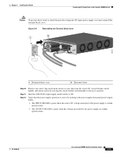
... the source DC circuit breaker switch handle, and restore power by the power supply are within specifications. 78-18350-02 Cisco Catalyst 4900M Switch Installation Guide 3-13 Turn the 1000 W DC-input supply on (|) position. Verify that the power supply operation is correct by looking at the power supply front panel power supply LEDs: • The INPUT OK LED is green...
... the source DC circuit breaker switch handle, and restore power by the power supply are within specifications. 78-18350-02 Cisco Catalyst 4900M Switch Installation Guide 3-13 Turn the 1000 W DC-input supply on (|) position. Verify that the power supply operation is correct by looking at the power supply front panel power supply LEDs: • The INPUT OK LED is green...


