
Data Sheet
Page 7
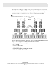
...and inter-metro network deployments with the following features: - Ethernet over MPLS (EoMPLS) - All contents are Copyright © 1992-2004 Cisco Systems, Inc. All rights reserved. • ISP network-Provides robust high-availability, security, and manageability features; Figure 3 Deployment Scenarios for...64257;c shaping. High-performance 10-Gigabit Ethernet uplinks - 802.1Q tunneling - Security, high availability, and manageability Cisco Systems, Inc. high-performance Gigabit and 10 Gigabit interface modules; Layer 2 and Layer 3 QoS - Network Equipment Building Standards...
...and inter-metro network deployments with the following features: - Ethernet over MPLS (EoMPLS) - All contents are Copyright © 1992-2004 Cisco Systems, Inc. All rights reserved. • ISP network-Provides robust high-availability, security, and manageability features; Figure 3 Deployment Scenarios for...64257;c shaping. High-performance 10-Gigabit Ethernet uplinks - 802.1Q tunneling - Security, high availability, and manageability Cisco Systems, Inc. high-performance Gigabit and 10 Gigabit interface modules; Layer 2 and Layer 3 QoS - Network Equipment Building Standards...
Data Sheet
Page 18
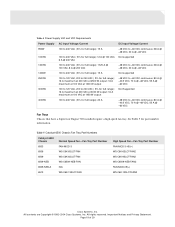
... chassis requires a 2500W or 4000W power supply. The 3-slot chassis requires a 950W power supply. All rights reserved. The 6- The power supplies are NEBS Level-3 compliant and use the online Cisco Dynamic Configuration Tool to two load-sharing, fault-tolerant, hot-swappable AC or DC power supplies. The tool is available...
... chassis requires a 2500W or 4000W power supply. The 3-slot chassis requires a 950W power supply. All rights reserved. The 6- The power supplies are NEBS Level-3 compliant and use the online Cisco Dynamic Configuration Tool to two load-sharing, fault-tolerant, hot-swappable AC or DC power supplies. The tool is available...
Data Sheet
Page 19
... Tray Part Number 6503 FAN-MOD-3 6506 WS-C6K-6SLOT-FAN 6509 WS-C6K-6SLOT-FAN 6509-NEB WS-C6509-NEB-FAN 6509-NEB-A N/A 6513 WS-C6K-13SLOT-FAN High Speed Fan-Fan Tray Part Number FAN-MOD-3-HS(=) WS-C6K-6SLOT-FAN2 WS-C6K-9SLOT-FAN2 WS-C6509-NEB-FAN2 FAN-MOD-09(=) WS-C6K-13SLOT-FAN2 Cisco Systems, Inc. See Table 5 for full...
... Tray Part Number 6503 FAN-MOD-3 6506 WS-C6K-6SLOT-FAN 6509 WS-C6K-6SLOT-FAN 6509-NEB WS-C6509-NEB-FAN 6509-NEB-A N/A 6513 WS-C6K-13SLOT-FAN High Speed Fan-Fan Tray Part Number FAN-MOD-3-HS(=) WS-C6K-6SLOT-FAN2 WS-C6K-9SLOT-FAN2 WS-C6509-NEB-FAN2 FAN-MOD-09(=) WS-C6K-13SLOT-FAN2 Cisco Systems, Inc. See Table 5 for full...
Data Sheet
Page 20
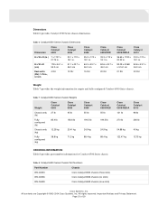
...64.0 x 43.7 x 46.0 cm Rack units (RU); 1.75 in., 4.4 cm 4 RU 12 RU 15 RU Cisco Catalyst 6509-NEB 33.3 x 17.2 x 18.1 in. 84.6 x 43.7 x 46.0 cm 20 RU Cisco Catalyst 6509-NEB-A Cisco Catalyst 6513 36.65 x 17.20 x 33.3 x 17.3 x 20.32 in. 18.1 in . Table 7 Catalyst...Series chassis. Table 8 Catalyst 6500 Series Chassis Part Numbers Part Number Chassis WS-C6503 Cisco Catalyst 6503 chassis (three slots) WS-C6506 Cisco Catalyst 6506 chassis (six slots) WS-C6509 Cisco Catalyst 6509 chassis (nine slots) Cisco Systems, Inc. Important Notices and Privacy Statement. Page 20 of 29 All ...
...64.0 x 43.7 x 46.0 cm Rack units (RU); 1.75 in., 4.4 cm 4 RU 12 RU 15 RU Cisco Catalyst 6509-NEB 33.3 x 17.2 x 18.1 in. 84.6 x 43.7 x 46.0 cm 20 RU Cisco Catalyst 6509-NEB-A Cisco Catalyst 6513 36.65 x 17.20 x 33.3 x 17.3 x 20.32 in. 18.1 in . Table 7 Catalyst...Series chassis. Table 8 Catalyst 6500 Series Chassis Part Numbers Part Number Chassis WS-C6503 Cisco Catalyst 6503 chassis (three slots) WS-C6506 Cisco Catalyst 6506 chassis (six slots) WS-C6509 Cisco Catalyst 6509 chassis (nine slots) Cisco Systems, Inc. Important Notices and Privacy Statement. Page 20 of 29 All ...
Data Sheet
Page 21
All contents are Copyright © 1992-2004 Cisco Systems, Inc. Page 21 of 29 All rights reserved. Important Notices and Privacy Statement. Table 9 Catalyst 6500 Series ... 6500 Series Chassis. Table 8 Catalyst 6500 Series Chassis Part Numbers (Continued) Part Number Chassis WS-C6509-NEB Cisco Catalyst 6509-NEB chassis (nine vertically oriented slots) WS-C6509-NEB-A Cisco Catalyst 6509-NEB chassis (nine vertically oriented slots)-enhanced WS-C6513 Cisco Catalyst 6513 chassis (13 slots) Environmental Conditions Table 9 provides environmental information for system confi...
All contents are Copyright © 1992-2004 Cisco Systems, Inc. Page 21 of 29 All rights reserved. Important Notices and Privacy Statement. Table 9 Catalyst 6500 Series ... 6500 Series Chassis. Table 8 Catalyst 6500 Series Chassis Part Numbers (Continued) Part Number Chassis WS-C6509-NEB Cisco Catalyst 6509-NEB chassis (nine vertically oriented slots) WS-C6509-NEB-A Cisco Catalyst 6509-NEB chassis (nine vertically oriented slots)-enhanced WS-C6513 Cisco Catalyst 6513 chassis (13 slots) Environmental Conditions Table 9 provides environmental information for system confi...
Data Sheet
Page 22
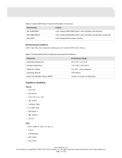
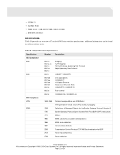
... of Catalyst 6500 Series switches specifications, additional information can be found in software release notes. • CISPR 22 • AS/NZS 3548 • NEBS Level 3 (GR-1089-CORE, GR-63-CORE) • ETSI ETS-300386-2 SPECIFICATIONS Table 10 provides an overview of Managed Objects for the Border Gateway Protocol... reflection 1997 Communities attribute 2385 Transmission Control Protocol (TCP) MD5 authentication for BGP 2439 Route flap dampening 2796 Route reflection Cisco Systems, Inc. Page 22 of 29 All contents are Copyright © 1992-2004...
... of Catalyst 6500 Series switches specifications, additional information can be found in software release notes. • CISPR 22 • AS/NZS 3548 • NEBS Level 3 (GR-1089-CORE, GR-63-CORE) • ETSI ETS-300386-2 SPECIFICATIONS Table 10 provides an overview of Managed Objects for the Border Gateway Protocol... reflection 1997 Communities attribute 2385 Transmission Control Protocol (TCP) MD5 authentication for BGP 2439 Route flap dampening 2796 Route reflection Cisco Systems, Inc. Page 22 of 29 All contents are Copyright © 1992-2004...
Upgrade Guide
Page 1
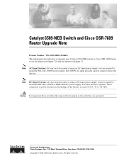
...Inc. All rights reserved. Caution It is important that you are required to power the fan tray. Catalyst 6509-NEB Switch and Cisco OSR-7609 Router Upgrade Note Product Number: WS-6509-NEB-UPGRD= This publication describes how to upgrade your switch or router is using a DC-input power supply, you ...the order they are presented. You must provide a separate, direct connection to install the WS-CDC-2500W or PWR-4000-DC power supply. Note AC-Input Systems-If your Catalyst 6509-NEB switch or Cisco OSR-7609 Router to use the Supervisor Engine 720 and the Supervisor Engine 32. Note...
...Inc. All rights reserved. Caution It is important that you are required to power the fan tray. Catalyst 6509-NEB Switch and Cisco OSR-7609 Router Upgrade Note Product Number: WS-6509-NEB-UPGRD= This publication describes how to upgrade your switch or router is using a DC-input power supply, you ...the order they are presented. You must provide a separate, direct connection to install the WS-CDC-2500W or PWR-4000-DC power supply. Note AC-Input Systems-If your Catalyst 6509-NEB switch or Cisco OSR-7609 Router to use the Supervisor Engine 720 and the Supervisor Engine 32. Note...
Upgrade Guide
Page 2
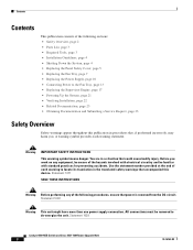
... Safety Overview Safety warnings appear throughout this device. You are in the translated safety warnings that could cause bodily injury. Statement 1028 Catalyst 6509-NEB Switch and Cisco OSR-7609 Router Upgrade Note 2 78-16162-02 Use the statement number provided at the end of each warning statement. Statement 1003 Warning This...
... Safety Overview Safety warnings appear throughout this device. You are in the translated safety warnings that could cause bodily injury. Statement 1028 Catalyst 6509-NEB Switch and Cisco OSR-7609 Router Upgrade Note 2 78-16162-02 Use the statement number provided at the end of each warning statement. Statement 1003 Warning This...
Upgrade Guide
Page 3
... cover The panel safety cover provides increased chassis airflow. • Two fan tray power cables (for DC-input systems) 78-16162-02 Catalyst 6509-NEB Switch and Cisco OSR-7609 Router Upgrade Note 3 Statement 1034 Warning This product requires short-circuit (overcurrent) protection, to install, replace, or service this equipment. Use caution...
... cover The panel safety cover provides increased chassis airflow. • Two fan tray power cables (for DC-input systems) 78-16162-02 Catalyst 6509-NEB Switch and Cisco OSR-7609 Router Upgrade Note 3 Statement 1034 Warning This product requires short-circuit (overcurrent) protection, to install, replace, or service this equipment. Use caution...
Upgrade Guide
Page 4
.... • If your switch or router is using an AC-input power supply, you should first upload the current configuration to install the WS-CAC-3000W power supply. Caution Always use an ESD wrist strap when handling modules or coming into contact with dual power supplies, connect each ...and unplug the power cord. Each input of the supervisor engine. Before you shut down the system, you are presented. Statement 1 Catalyst 6509-NEB Switch and Cisco OSR-7609 Router Upgrade Note 4 78-16162-02 Caution Use both hands to the nonvolatile memory of the fan tray is rated 10 A @ ...
.... • If your switch or router is using an AC-input power supply, you should first upload the current configuration to install the WS-CAC-3000W power supply. Caution Always use an ESD wrist strap when handling modules or coming into contact with dual power supplies, connect each ...and unplug the power cord. Each input of the supervisor engine. Before you shut down the system, you are presented. Statement 1 Catalyst 6509-NEB Switch and Cisco OSR-7609 Router Upgrade Note 4 78-16162-02 Caution Use both hands to the nonvolatile memory of the fan tray is rated 10 A @ ...
Upgrade Guide
Page 5
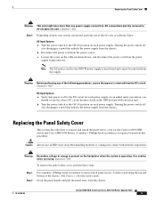
...and install the panel safety cover for each power supply. Turning the power switch off to the DC circuit for the Catalyst 6509-NEB switch and Cisco OSR-7609 Router. Caution Always use an ESD wrist strap when handling modules or coming into contact with electrical tape. Grasp the ... device, and disconnect the power cord from the power source. b. All connections must be removed from the chassis. 78-16162-02 Catalyst 6509-NEB Switch and Cisco OSR-7609 Router Upgrade Note 5 Statement 1028 Step 2 Depending on each located along the top and bottom of the chassis. (See Figure 1.)...
...and install the panel safety cover for each power supply. Turning the power switch off to the DC circuit for the Catalyst 6509-NEB switch and Cisco OSR-7609 Router. Caution Always use an ESD wrist strap when handling modules or coming into contact with electrical tape. Grasp the ... device, and disconnect the power cord from the power source. b. All connections must be removed from the chassis. 78-16162-02 Catalyst 6509-NEB Switch and Cisco OSR-7609 Router Upgrade Note 5 Statement 1028 Step 2 Depending on each located along the top and bottom of the chassis. (See Figure 1.)...
Upgrade Guide
Page 6
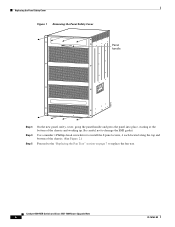
... at the bottom of the chassis. (See Figure 2.) Proceed to the "Replacing the Fan Tray" section on page 7 to replace the fan tray. Catalyst 6509-NEB Switch and Cisco OSR-7609 Router Upgrade Note 6 78-16162-02 Be careful not to damage the EMI gasket.
... at the bottom of the chassis. (See Figure 2.) Proceed to the "Replacing the Fan Tray" section on page 7 to replace the fan tray. Catalyst 6509-NEB Switch and Cisco OSR-7609 Router Upgrade Note 6 78-16162-02 Be careful not to damage the EMI gasket.
Upgrade Guide
Page 7
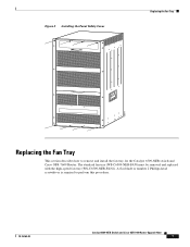
Figure 2 Installing the Panel Safety Cover Replacing the Fan Tray 105071 Replacing the Fan Tray This section describes how to perform this procedure. 78-16162-02 Catalyst 6509-NEB Switch and Cisco OSR-7609 Router Upgrade Note 7 The standard fan tray (WS-C6509-NEB-FAN) must be removed and replaced with the high-speed fan tray (WS-C6509-NEB-FAN2). A flat-blade or number 2 Phillips-head screwdriver is required to remove and install the fan tray for the Catalyst 6509-NEB switch and Cisco OSR-7609 Router.
Figure 2 Installing the Panel Safety Cover Replacing the Fan Tray 105071 Replacing the Fan Tray This section describes how to perform this procedure. 78-16162-02 Catalyst 6509-NEB Switch and Cisco OSR-7609 Router Upgrade Note 7 The standard fan tray (WS-C6509-NEB-FAN) must be removed and replaced with the high-speed fan tray (WS-C6509-NEB-FAN2). A flat-blade or number 2 Phillips-head screwdriver is required to remove and install the fan tray for the Catalyst 6509-NEB switch and Cisco OSR-7609 Router.
Upgrade Guide
Page 8
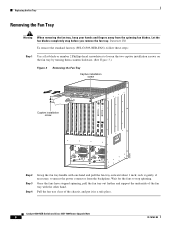
...WS-X6K-SUP2-2GE STATUSSYSTEMCONSOLPEWR MGRMETSET SUPERVISOR2 WS-X6K-SUP2-2GE STATUSSYSTEMCONSOLPEWR MGRMETSET SUPERVISOR2 WS... LINK 5 LINK 4 LINK 3 LINK 2 LINK WS-X6224 1 STATUS LINK 24 PORT 100FX 24 23... LINK 3 LINK 2 LINK WS-X6224 1 STATUS LINK 24... LINK 2 LINK WS-X6224 1 STATUS LINK 24 PORT... 11 10 9 8 PORT GIGABIT ETHERNET WS-X6408 8 PORT GIGABIT ETHERNET STATUS LINK ...6 LINK LINK 6 LINK 7 LINK LINK 7 LINK 8 LINK LINK 8 LINK WS-X6408 8 PORT GIGABIT ETHERNET EJECT EJECT 4 5 Switch Load 100% 1% Switch...standard fan tray (WS-C6509-NEB-FAN), follow ...
...WS-X6K-SUP2-2GE STATUSSYSTEMCONSOLPEWR MGRMETSET SUPERVISOR2 WS-X6K-SUP2-2GE STATUSSYSTEMCONSOLPEWR MGRMETSET SUPERVISOR2 WS... LINK 5 LINK 4 LINK 3 LINK 2 LINK WS-X6224 1 STATUS LINK 24 PORT 100FX 24 23... LINK 3 LINK 2 LINK WS-X6224 1 STATUS LINK 24... LINK 2 LINK WS-X6224 1 STATUS LINK 24 PORT... 11 10 9 8 PORT GIGABIT ETHERNET WS-X6408 8 PORT GIGABIT ETHERNET STATUS LINK ...6 LINK LINK 6 LINK 7 LINK LINK 7 LINK 8 LINK LINK 8 LINK WS-X6408 8 PORT GIGABIT ETHERNET EJECT EJECT 4 5 Switch Load 100% 1% Switch...standard fan tray (WS-C6509-NEB-FAN), follow ...
Upgrade Guide
Page 9
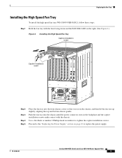
Replacing the Fan Tray Installing the High Speed Fan Tray To install the high speed fan tray (WS-C6509-NEB-FAN2), follow these steps: Step 1 Hold the fan tray with the fans facing down and ...LINK LINK LINK LINK LINK LINK LINK LINK LINK LINK LINK LINK LINK LINK 8 LINK 7 LINK 6 LINK 5 LINK 4 LINK 3 LINK 2 LINK WS-X6224 1 STATUS LINK 24 PORT 100FX HIGH SPEED FAN 24 23 22 21 20 19 18 17 16 15 14 13 12 11 10 9 LINK...number 2 Phillips-head screwdriver to replace the power supply. 78-16162-02 Catalyst 6509-NEB Switch and Cisco OSR-7609 Router Upgrade Note 9
Replacing the Fan Tray Installing the High Speed Fan Tray To install the high speed fan tray (WS-C6509-NEB-FAN2), follow these steps: Step 1 Hold the fan tray with the fans facing down and ...LINK LINK LINK LINK LINK LINK LINK LINK LINK LINK LINK LINK LINK LINK 8 LINK 7 LINK 6 LINK 5 LINK 4 LINK 3 LINK 2 LINK WS-X6224 1 STATUS LINK 24 PORT 100FX HIGH SPEED FAN 24 23 22 21 20 19 18 17 16 15 14 13 12 11 10 9 LINK...number 2 Phillips-head screwdriver to replace the power supply. 78-16162-02 Catalyst 6509-NEB Switch and Cisco OSR-7609 Router Upgrade Note 9
Upgrade Guide
Page 10
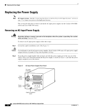
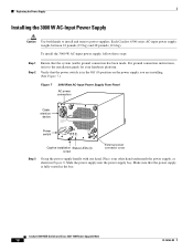
... the Power Supply Replacing the Power Supply Note DC-input systems-See the "Connecting Site Power to the Fan Tray for the Catalyst 6509-NEB switch and Cisco OSR-7609 router. Statement 1034 To remove an AC-input power supply, follow these steps: Step 1 Loosen the captive installation screw. (See Figure 5.) Caution... Supply Front Panel AC power connection Cable retention device Power switch I 0 INPUT OK FAN OUTPUT OK FAIL Status LEDs Captive installation screw 16029 Catalyst 6509-NEB Switch and Cisco OSR-7609 Router Upgrade Note 10 78-16162-02
... the Power Supply Replacing the Power Supply Note DC-input systems-See the "Connecting Site Power to the Fan Tray for the Catalyst 6509-NEB switch and Cisco OSR-7609 router. Statement 1034 To remove an AC-input power supply, follow these steps: Step 1 Loosen the captive installation screw. (See Figure 5.) Caution... Supply Front Panel AC power connection Cable retention device Power switch I 0 INPUT OK FAN OUTPUT OK FAIL Status LEDs Captive installation screw 16029 Catalyst 6509-NEB Switch and Cisco OSR-7609 Router Upgrade Note 10 78-16162-02
Upgrade Guide
Page 11
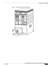
Catalyst 6509-NEB Switch and Cisco OSR-7609 Router Upgrade Note 11 Replacing the Power Supply 105074 48V INPUT 2 FAN FAIL INPOUT POWER GOOD RTN -48VDC GND HIGH SPEED FAN SELECT STATUS ACTIVE Figure 6 Removing an AC-Input Power Supply WS-X6K-SUP2-2GE STATUSSYSTEMCONSOLPEWR MGRMETSET ... CAARLRAIREMR RX PORT 1 CAARLRAIREMR RX PORT 2 CAARLRAIREMR RX PORT 3 CAARLRAIREMR RX LINK 4 NEXT SWITCH FABRIC MDL WS-C6500-SFM SELECT STATUS ACTIVE NEXT OK FAIL INPUT FAN OUTPUT WS-C6500-NEB-FAN2 GOOD GND INPOUT POWER SWITCH FABRIC MDL OSM-40C12-POS-MM STATUS OC12 POS MM 1 2 LINK 1...
Catalyst 6509-NEB Switch and Cisco OSR-7609 Router Upgrade Note 11 Replacing the Power Supply 105074 48V INPUT 2 FAN FAIL INPOUT POWER GOOD RTN -48VDC GND HIGH SPEED FAN SELECT STATUS ACTIVE Figure 6 Removing an AC-Input Power Supply WS-X6K-SUP2-2GE STATUSSYSTEMCONSOLPEWR MGRMETSET ... CAARLRAIREMR RX PORT 1 CAARLRAIREMR RX PORT 2 CAARLRAIREMR RX PORT 3 CAARLRAIREMR RX LINK 4 NEXT SWITCH FABRIC MDL WS-C6500-SFM SELECT STATUS ACTIVE NEXT OK FAIL INPUT FAN OUTPUT WS-C6500-NEB-FAN2 GOOD GND INPOUT POWER SWITCH FABRIC MDL OSM-40C12-POS-MM STATUS OC12 POS MM 1 2 LINK 1...
Upgrade Guide
Page 12
... the bay. For ground connection instructions, refer to install and remove power supplies. Slide the power supply into the power supply bay. Catalyst 6509-NEB Switch and Cisco OSR-7609 Router Upgrade Note 12 78-16162-02 Place your hardware platform. Replacing the Power Supply Installing the 3000 W AC-Input Power Supply...
... the bay. For ground connection instructions, refer to install and remove power supplies. Slide the power supply into the power supply bay. Catalyst 6509-NEB Switch and Cisco OSR-7609 Router Upgrade Note 12 78-16162-02 Place your hardware platform. Replacing the Power Supply Installing the 3000 W AC-Input Power Supply...
Upgrade Guide
Page 13
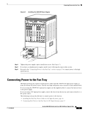
...connect power to the fan tray: • Installing the Fan Tray Power Cable for DC-Input Systems, page 15 78-16162-02 Catalyst 6509-NEB Switch and Cisco OSR-7609 Router Upgrade Note 13 The fan tray ships with power wires secured at each terminal block. Figure 8 Installing the 3000 W Power... Supply LINK 1 8 PORT OC3 POS MM 2 STATUS OSM-8OC3-POS MM 1 FAN STATUS 48V INPUT 1 INPOUT POWER RTN -48VDC GOOD GND WS-C6500-NEB-FAN2 LINK 1 8 ...
...connect power to the fan tray: • Installing the Fan Tray Power Cable for DC-Input Systems, page 15 78-16162-02 Catalyst 6509-NEB Switch and Cisco OSR-7609 Router Upgrade Note 13 The fan tray ships with power wires secured at each terminal block. Figure 8 Installing the 3000 W Power... Supply LINK 1 8 PORT OC3 POS MM 2 STATUS OSM-8OC3-POS MM 1 FAN STATUS 48V INPUT 1 INPOUT POWER RTN -48VDC GOOD GND WS-C6500-NEB-FAN2 LINK 1 8 ...
Upgrade Guide
Page 14
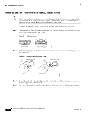
... supply using the supplied cables. If you have redundant power supplies, repeat the steps in this section for the redundant power supply. Catalyst 6509-NEB Switch and Cisco OSR-7609 Router Upgrade Note 14 78-16162-02 Connecting Power to the Fan Tray Installing the Fan Tray Power Cable for the redundant...
... supply using the supplied cables. If you have redundant power supplies, repeat the steps in this section for the redundant power supply. Catalyst 6509-NEB Switch and Cisco OSR-7609 Router Upgrade Note 14 78-16162-02 Connecting Power to the Fan Tray Installing the Fan Tray Power Cable for the redundant...