
Data Sheet
Page 5
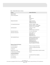
...up to 210 Mpps Supervisor 720: up to 400 Mpps Catalyst OS (CatOS) Cisco IOS CatOS/IOS Hybrid Configuration Yes, with stateful failover Power supplies (1+1) Switch fabric (1+1) Replaceable clock Replaceable fan tray Gateway Load Balancing Protocol Hot Standby Router Protocol Multimodule EtherChannel Rapid Spanning Tree ... 288 ports 194 ports (2 ports provided on supervisor engine) 32 ports 12 modules with 24 port adapters 192 48 Cisco Systems, Inc. All contents are Copyright © 1992-2004 Cisco Systems, Inc. All rights reserved. Page 5 of 29 Important Notices and Privacy Statement.
...up to 210 Mpps Supervisor 720: up to 400 Mpps Catalyst OS (CatOS) Cisco IOS CatOS/IOS Hybrid Configuration Yes, with stateful failover Power supplies (1+1) Switch fabric (1+1) Replaceable clock Replaceable fan tray Gateway Load Balancing Protocol Hot Standby Router Protocol Multimodule EtherChannel Rapid Spanning Tree ... 288 ports 194 ports (2 ports provided on supervisor engine) 32 ports 12 modules with 24 port adapters 192 48 Cisco Systems, Inc. All contents are Copyright © 1992-2004 Cisco Systems, Inc. All rights reserved. Page 5 of 29 Important Notices and Privacy Statement.
Data Sheet
Page 18
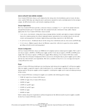
... and supervisor engines with larger chassis for network security and management; The 3-slot chassis requires a 950W power supply. Chassis Applications The Cisco Catalyst 6500 Series provides a selection of 29 Page 18 of chassis, including 3-, 6-, 9-, and 13-slot models with slots arranged horizontally...be removed without powering off the system. All rights reserved. CISCO CATALYST 6500 SERIES CHASSIS Cisco Catalyst 6500 Series chassis can be deployed in selecting the chassis, power supplies, power cables, and fan trays that will meet your requirements. and 9-slot chassis-Traditional ...
... and supervisor engines with larger chassis for network security and management; The 3-slot chassis requires a 950W power supply. Chassis Applications The Cisco Catalyst 6500 Series provides a selection of 29 Page 18 of chassis, including 3-, 6-, 9-, and 13-slot models with slots arranged horizontally...be removed without powering off the system. All rights reserved. CISCO CATALYST 6500 SERIES CHASSIS Cisco Catalyst 6500 Series chassis can be deployed in selecting the chassis, power supplies, power cables, and fan trays that will meet your requirements. and 9-slot chassis-Traditional ...
Data Sheet
Page 19
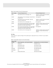
... Numbers Catalyst 6500 Chassis Normal Speed Fan-Fan Tray Part Number 6503 FAN-MOD-3 6506 WS-C6K-6SLOT-FAN 6509 WS-C6K-6SLOT-FAN 6509-NEB WS-C6509-NEB-FAN 6509-NEB-A N/A 6513 WS-C6K-13SLOT-FAN High Speed Fan-Fan Tray Part Number FAN-MOD-3-HS(=) WS-C6K-6SLOT-FAN2 WS-C6K-9SLOT-FAN2 WS-C6509-NEB-FAN2 FAN-MOD-09(=) WS-C6K-13SLOT-FAN2 Cisco Systems, Inc. Page 19 of...
... Numbers Catalyst 6500 Chassis Normal Speed Fan-Fan Tray Part Number 6503 FAN-MOD-3 6506 WS-C6K-6SLOT-FAN 6509 WS-C6K-6SLOT-FAN 6509-NEB WS-C6509-NEB-FAN 6509-NEB-A N/A 6513 WS-C6K-13SLOT-FAN High Speed Fan-Fan Tray Part Number FAN-MOD-3-HS(=) WS-C6K-6SLOT-FAN2 WS-C6K-9SLOT-FAN2 WS-C6509-NEB-FAN2 FAN-MOD-09(=) WS-C6K-13SLOT-FAN2 Cisco Systems, Inc. Page 19 of...
User Guide
Page 4
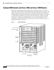
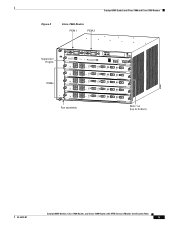
... costs. The Catalyst 6509 switch and the Cisco 7606 and Cisco 7609 routers provide a scalable, secure, manageable remote access server that meets FIPS 140-2 Level 2 requirements, as a multi-chip standalone module. Figure 1 Catalyst 6509 Switch Supervisor engine Redundant supervisor engine Switching modules Fan assembly 1 2 3 4 5 6 7 8 FAN STATUS 9 WS-X6K-SUP2-2GE STATUS SYSTEMCONSOLPEWR MGRMETSET SUPERVISOR2 CONSOLE...
... costs. The Catalyst 6509 switch and the Cisco 7606 and Cisco 7609 routers provide a scalable, secure, manageable remote access server that meets FIPS 140-2 Level 2 requirements, as a multi-chip standalone module. Figure 1 Catalyst 6509 Switch Supervisor engine Redundant supervisor engine Switching modules Fan assembly 1 2 3 4 5 6 7 8 FAN STATUS 9 WS-X6K-SUP2-2GE STATUS SYSTEMCONSOLPEWR MGRMETSET SUPERVISOR2 CONSOLE...
User Guide
Page 5
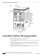
Catalyst 6509 Switch and Cisco 7606 and Cisco 7609 Routers Figure 2 Cisco 7606 Router PEM 1 PEM 2 Supervisor Engine OSMs WS-X6K-SUP2-2GE STATUS SYSTEMCONSOLPEWR MGRMETSET SUPERVISOR2 CONSOLE CONSOLE PORT MODE PCMCIA EJECT OSM-4OC12 POS-SI 1 STATUS 2 4 PORT OC-12 POS SM IR ...TX PORT 3 ACTIVE TX RX CARRAILEARRM RX TX PORT4 ACTIVE TX RX CARRAILEARRM RX TX PORT 3 ACTIVE TX RX CARRAILEARRM RX TX PORT4 Fan assembly Slots 1-6 (top to bottom) 63892 OL-6334-01 Catalyst 6509 Switch, Cisco 7606 Router, and Cisco 7609 Router with VPN Services Module Certification Note 5
Catalyst 6509 Switch and Cisco 7606 and Cisco 7609 Routers Figure 2 Cisco 7606 Router PEM 1 PEM 2 Supervisor Engine OSMs WS-X6K-SUP2-2GE STATUS SYSTEMCONSOLPEWR MGRMETSET SUPERVISOR2 CONSOLE CONSOLE PORT MODE PCMCIA EJECT OSM-4OC12 POS-SI 1 STATUS 2 4 PORT OC-12 POS SM IR ...TX PORT 3 ACTIVE TX RX CARRAILEARRM RX TX PORT4 ACTIVE TX RX CARRAILEARRM RX TX PORT 3 ACTIVE TX RX CARRAILEARRM RX TX PORT4 Fan assembly Slots 1-6 (top to bottom) 63892 OL-6334-01 Catalyst 6509 Switch, Cisco 7606 Router, and Cisco 7609 Router with VPN Services Module Certification Note 5
User Guide
Page 6
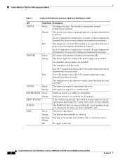
... Figure 3 Cisco 7609 Router WS-X6K-SUP2-2GE STATUSSYSTEMCONSOLPEWR MGRMETSET CONSOLE SUPERVISOR2 WS-X6K-SUP2-2GE STATUSSYSTEMCONSOLPEWR MGRMETSET CONSOLE SUPERVISOR2 OSM-40C12-POS-MM OC12 POS MM OSM-40C12-POS-MM STATUS OC12 POS MM WS-C6500-SFM STATUS 2 1 1 2 LINK 1 LINK 1 LINK 2 LINK 2 3 3 CONSOLE PORT MODE CONSOLE PORT MODE 4 LINK 3 4 LINK 3 OSMs FAN STATUS Fan assembly...
... Figure 3 Cisco 7609 Router WS-X6K-SUP2-2GE STATUSSYSTEMCONSOLPEWR MGRMETSET CONSOLE SUPERVISOR2 WS-X6K-SUP2-2GE STATUSSYSTEMCONSOLPEWR MGRMETSET CONSOLE SUPERVISOR2 OSM-40C12-POS-MM OC12 POS MM OSM-40C12-POS-MM STATUS OC12 POS MM WS-C6500-SFM STATUS 2 1 1 2 LINK 1 LINK 1 LINK 2 LINK 2 3 3 CONSOLE PORT MODE CONSOLE PORT MODE 4 LINK 3 4 LINK 3 OSMs FAN STATUS Fan assembly...
User Guide
Page 8
...been exceeded during environmental monitoring.) All chassis environmental monitors are installed. Orange The power supply has failed or the power supply fan has failed. Incompatible power supplies are reporting OK. LINK Green The port is not available for all modules. The redundant ...hardware failure. Flashing The link is not operational because a fault occurred during the initialization sequence. Catalyst 6509 Switch, Cisco 7606 Router, and Cisco 7609 Router with VPN Services Module Certification Note 8 OL-6334-01 PCMCIA The PCMCIA LED is lit when no Flash...
...been exceeded during environmental monitoring.) All chassis environmental monitors are installed. Orange The power supply has failed or the power supply fan has failed. Incompatible power supplies are reporting OK. LINK Green The port is not available for all modules. The redundant ...hardware failure. Flashing The link is not operational because a fault occurred during the initialization sequence. Catalyst 6509 Switch, Cisco 7606 Router, and Cisco 7609 Router with VPN Services Module Certification Note 8 OL-6334-01 PCMCIA The PCMCIA LED is lit when no Flash...
User Guide
Page 14
...the Catalyst 6509 Switch Opacity shield material removed for clarity Shield screw WS-X6K-SUP2-2GE 1 STATUS SYSTEMCONSOLPEWR MGRMETSET CONSOLE PORT CONSOLE MODE SUPERVISOR2 2 3 WS-SVC-IPSEC-1 4 STATUS IPSec VPN Acceleration Services Module 5 6 7 8 FAN STATUS 9 PCMCIA EJECT Switch Load 100% 1% PORT 1 LINK ...PORT 2 LINK o o INPUT OK FAN OUTPUT OK FAIL INPUT OK FAN OUTPUT OK FAIL Chassis shown removed from rack for clarity M-4 snap rivet pin M-4 snap rivet sleeve Catalyst 6509 Switch, Cisco 7606 Router, and Cisco 7609 Router with VPN Services Module Certification ...
...the Catalyst 6509 Switch Opacity shield material removed for clarity Shield screw WS-X6K-SUP2-2GE 1 STATUS SYSTEMCONSOLPEWR MGRMETSET CONSOLE PORT CONSOLE MODE SUPERVISOR2 2 3 WS-SVC-IPSEC-1 4 STATUS IPSec VPN Acceleration Services Module 5 6 7 8 FAN STATUS 9 PCMCIA EJECT Switch Load 100% 1% PORT 1 LINK ...PORT 2 LINK o o INPUT OK FAN OUTPUT OK FAIL INPUT OK FAN OUTPUT OK FAIL Chassis shown removed from rack for clarity M-4 snap rivet pin M-4 snap rivet sleeve Catalyst 6509 Switch, Cisco 7606 Router, and Cisco 7609 Router with VPN Services Module Certification ...
User Guide
Page 18
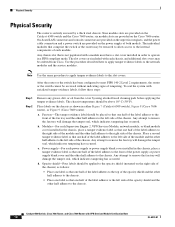
...to the left side of the chassis) as shown in either Figure 7 (Catalyst 6509 switch), Figure 8 (Cisco 7606 router), or Figure 9 (Cisco 7609 router). Any attempt to remove the fan tray will damage the tamper seal, which indicates tampering has occurred. six module slots are provided on the right...to the chassis. a. d. Opacity shield-Four labels should be applied to the opacity shield (mounted on the Catalyst 6509 switch and the Cisco 7609 router; On-board LAN connectors and console connectors are provided on the power supply of the chassis. The individual modules that one ...
...to the left side of the chassis) as shown in either Figure 7 (Catalyst 6509 switch), Figure 8 (Cisco 7606 router), or Figure 9 (Cisco 7609 router). Any attempt to remove the fan tray will damage the tamper seal, which indicates tampering has occurred. six module slots are provided on the right...to the chassis. a. d. Opacity shield-Four labels should be applied to the opacity shield (mounted on the Catalyst 6509 switch and the Cisco 7609 router; On-board LAN connectors and console connectors are provided on the power supply of the chassis. The individual modules that one ...
User Guide
Page 19
... MGRMETSET CONSOLE PORT CONSOLE MODE SUPERVISOR2 2 3 WS-SVC-IPSEC-1 4 STATUS IPSec VPN Acceleration Services Module 5 6 7 8 FAN STATUS 9 PCMCIA EJECT Switch Load 100% 1% PORT 1 LINK PORT 2 LINK o o INPUT OK FAN OUTPUT OK FAIL INPUT OK FAN OUTPUT OK FAIL 130878 OL-6334-01 Catalyst 6509 Switch, Cisco 7606 Router, and Cisco 7609 Router with VPN Services Module...
... MGRMETSET CONSOLE PORT CONSOLE MODE SUPERVISOR2 2 3 WS-SVC-IPSEC-1 4 STATUS IPSec VPN Acceleration Services Module 5 6 7 8 FAN STATUS 9 PCMCIA EJECT Switch Load 100% 1% PORT 1 LINK PORT 2 LINK o o INPUT OK FAN OUTPUT OK FAIL INPUT OK FAN OUTPUT OK FAIL 130878 OL-6334-01 Catalyst 6509 Switch, Cisco 7606 Router, and Cisco 7609 Router with VPN Services Module...
Upgrade Guide
Page 1
... in the order they are presented. Catalyst 6509-NEB Switch and Cisco OSR-7609 Router Upgrade Note Product Number: WS-6509-NEB-UPGRD= This publication describes how to upgrade your Catalyst 6509-NEB switch or Cisco OSR-7609 Router to power the fan tray. Caution It is rated 10 A @ -40 to power... the fan tray. The 3000 W AC-input provides a power output to -60 VDC....
... in the order they are presented. Catalyst 6509-NEB Switch and Cisco OSR-7609 Router Upgrade Note Product Number: WS-6509-NEB-UPGRD= This publication describes how to upgrade your Catalyst 6509-NEB switch or Cisco OSR-7609 Router to power the fan tray. Caution It is rated 10 A @ -40 to power... the fan tray. The 3000 W AC-input provides a power output to -60 VDC....
Upgrade Guide
Page 2
... • Installation Guidelines, page 4 • Shutting Down the System, page 4 • Replacing the Panel Safety Cover, page 5 • Replacing the Fan Tray, page 7 • Replacing the Power Supply, page 10 • Connecting Power to de-energize the unit. Statement 1071 SAVE THESE INSTRUCTIONS Warning Before ... device. Statement 1003 Warning This unit might have more than one power supply connection. Statement 1028 Catalyst 6509-NEB Switch and Cisco OSR-7609 Router Upgrade Note 2 78-16162-02 A warning symbol precedes each warning to locate its translation in the translated...
... • Installation Guidelines, page 4 • Shutting Down the System, page 4 • Replacing the Panel Safety Cover, page 5 • Replacing the Fan Tray, page 7 • Replacing the Power Supply, page 10 • Connecting Power to de-energize the unit. Statement 1071 SAVE THESE INSTRUCTIONS Warning Before ... device. Statement 1003 Warning This unit might have more than one power supply connection. Statement 1028 Catalyst 6509-NEB Switch and Cisco OSR-7609 Router Upgrade Note 2 78-16162-02 A warning symbol precedes each warning to locate its translation in the translated...
Upgrade Guide
Page 3
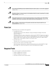
...cables are required to a DC power source. • One panel safety cover The panel safety cover provides increased chassis airflow. • Two fan tray power cables (for the Supervisor Engine 720 and the Supervisor Engine 32. Statement 1045 Warning When installing or replacing the unit, the ground...supplies. Use caution when servicing. Required Tools These tools are provided for DC-input systems) 78-16162-02 Catalyst 6509-NEB Switch and Cisco OSR-7609 Router Upgrade Note 3 Statement 1030 Warning Hazardous voltage or energy is present on the backplane when the system is operating. ...
...cables are required to a DC power source. • One panel safety cover The panel safety cover provides increased chassis airflow. • Two fan tray power cables (for the Supervisor Engine 720 and the Supervisor Engine 32. Statement 1045 Warning When installing or replacing the unit, the ground...supplies. Use caution when servicing. Required Tools These tools are provided for DC-input systems) 78-16162-02 Catalyst 6509-NEB Switch and Cisco OSR-7609 Router Upgrade Note 3 Statement 1030 Warning Hazardous voltage or energy is present on the backplane when the system is operating. ...
Upgrade Guide
Page 4
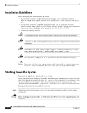
...steps: Step 1 Upload the current configuration to power the fan tray. Caution In a system with internal components. To properly shut down the system, you are required to install the WS-CAC-3000W power supply. On any modules running Cisco IOS, save the running configuration. Caution Always use an ...ESD wrist strap when handling modules or coming into contact with dual power supplies, connect each power supply to power the fan tray. • If...
...steps: Step 1 Upload the current configuration to power the fan tray. Caution In a system with internal components. To properly shut down the system, you are required to install the WS-CAC-3000W power supply. On any modules running Cisco IOS, save the running configuration. Caution Always use an ...ESD wrist strap when handling modules or coming into contact with dual power supplies, connect each power supply to power the fan tray. • If...
Upgrade Guide
Page 6
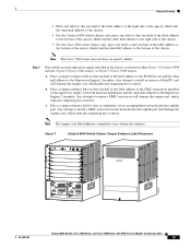
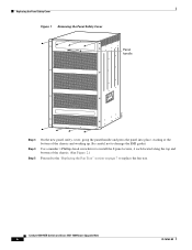
...-head screwdriver to install the 8 panel screws, 4 each located along the top and bottom of the chassis and working up. Catalyst 6509-NEB Switch and Cisco OSR-7609 Router Upgrade Note 6 78-16162-02 Replacing the Panel Safety Cover Figure 1 Removing the Panel Safety Cover Panel handle 105072 Step 3 Step 4 Step... cover, grasp the panel handle and press the panel into place, starting at the bottom of the chassis. (See Figure 2.) Proceed to the "Replacing the Fan Tray" section on page 7 to replace the fan tray. Be careful not to damage the EMI gasket.
...-head screwdriver to install the 8 panel screws, 4 each located along the top and bottom of the chassis and working up. Catalyst 6509-NEB Switch and Cisco OSR-7609 Router Upgrade Note 6 78-16162-02 Replacing the Panel Safety Cover Figure 1 Removing the Panel Safety Cover Panel handle 105072 Step 3 Step 4 Step... cover, grasp the panel handle and press the panel into place, starting at the bottom of the chassis. (See Figure 2.) Proceed to the "Replacing the Fan Tray" section on page 7 to replace the fan tray. Be careful not to damage the EMI gasket.
Upgrade Guide
Page 7
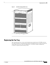
Figure 2 Installing the Panel Safety Cover Replacing the Fan Tray 105071 Replacing the Fan Tray This section describes how to perform this procedure. 78-16162-02 Catalyst 6509-NEB Switch and Cisco OSR-7609 Router Upgrade Note 7 A flat-blade or number 2 Phillips-head screwdriver is required to remove and install the fan tray for the Catalyst 6509-NEB switch and Cisco OSR-7609 Router. The standard fan tray (WS-C6509-NEB-FAN) must be removed and replaced with the high-speed fan tray (WS-C6509-NEB-FAN2).
Figure 2 Installing the Panel Safety Cover Replacing the Fan Tray 105071 Replacing the Fan Tray This section describes how to perform this procedure. 78-16162-02 Catalyst 6509-NEB Switch and Cisco OSR-7609 Router Upgrade Note 7 A flat-blade or number 2 Phillips-head screwdriver is required to remove and install the fan tray for the Catalyst 6509-NEB switch and Cisco OSR-7609 Router. The standard fan tray (WS-C6509-NEB-FAN) must be removed and replaced with the high-speed fan tray (WS-C6509-NEB-FAN2).
Upgrade Guide
Page 8
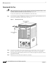
... To remove the standard fan tray (WS-C6509-NEB-FAN), follow these steps: Step 1 Use a flat-blade or number 2 Phillips-head screwdriver to stop before you remove the fan tray. Wait for the fans to loosen the two captive installation screws on the fan tray by turning them ...fan tray clear of the fan tray with one hand and pull the fan tray outward about 1 inch; Let the fan blades completely stop spinning. Replacing the Fan Tray Removing the Fan Tray Warning When removing the fan tray, keep your hands and fingers away from the backplane. Catalyst 6509-NEB Switch and Cisco...
... To remove the standard fan tray (WS-C6509-NEB-FAN), follow these steps: Step 1 Use a flat-blade or number 2 Phillips-head screwdriver to stop before you remove the fan tray. Wait for the fans to loosen the two captive installation screws on the fan tray by turning them ...fan tray clear of the fan tray with one hand and pull the fan tray outward about 1 inch; Let the fan blades completely stop spinning. Replacing the Fan Tray Removing the Fan Tray Warning When removing the fan tray, keep your hands and fingers away from the backplane. Catalyst 6509-NEB Switch and Cisco...
Upgrade Guide
Page 9
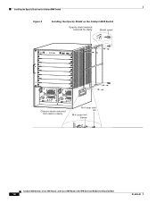
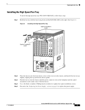
... on page 10 to tighten the captive installation screws. Replacing the Fan Tray Installing the High Speed Fan Tray To install the high speed fan tray (WS-C6509-NEB-FAN2), follow these steps: Step 1 Hold the fan tray with the fans facing down and the FAN FAIL LED on the right. (See Figure 4.) Figure 4 Installing...so that it rests on the chassis, and then lift the fan tray up slightly, aligning the top and bottom chassis guides. Use a flat-blade or number 2 Phillips-head screwdriver to replace the power supply. 78-16162-02 Catalyst 6509-NEB Switch and Cisco OSR-7609 Router Upgrade Note 9
... on page 10 to tighten the captive installation screws. Replacing the Fan Tray Installing the High Speed Fan Tray To install the high speed fan tray (WS-C6509-NEB-FAN2), follow these steps: Step 1 Hold the fan tray with the fans facing down and the FAN FAIL LED on the right. (See Figure 4.) Figure 4 Installing...so that it rests on the chassis, and then lift the fan tray up slightly, aligning the top and bottom chassis guides. Use a flat-blade or number 2 Phillips-head screwdriver to replace the power supply. 78-16162-02 Catalyst 6509-NEB Switch and Cisco OSR-7609 Router Upgrade Note 9
Upgrade Guide
Page 10
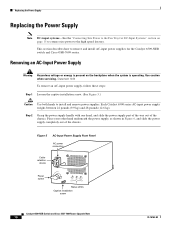
...supplies. Figure 5 AC-Input Power Supply Front Panel AC power connection Cable retention device Power switch I 0 INPUT OK FAN OUTPUT OK FAIL Status LEDs Captive installation screw 16029 Catalyst 6509-NEB Switch and Cisco OSR-7609 Router Upgrade Note 10 78-16162-02 Step 2 Grasp the power supply handle with one hand.... Removing an AC-Input Power Supply Warning Hazardous voltage or energy is present on page 15 to connect site power to the high speed fan tray. Replacing the Power Supply Replacing the Power Supply Note DC-input systems-See the "Connecting Site Power to the...
...supplies. Figure 5 AC-Input Power Supply Front Panel AC power connection Cable retention device Power switch I 0 INPUT OK FAN OUTPUT OK FAIL Status LEDs Captive installation screw 16029 Catalyst 6509-NEB Switch and Cisco OSR-7609 Router Upgrade Note 10 78-16162-02 Step 2 Grasp the power supply handle with one hand.... Removing an AC-Input Power Supply Warning Hazardous voltage or energy is present on page 15 to connect site power to the high speed fan tray. Replacing the Power Supply Replacing the Power Supply Note DC-input systems-See the "Connecting Site Power to the...
Upgrade Guide
Page 11
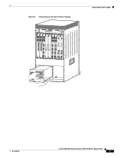
Catalyst 6509-NEB Switch and Cisco OSR-7609 Router Upgrade Note 11 Replacing the Power Supply 105074 48V INPUT 2 FAN FAIL INPOUT POWER GOOD RTN -48VDC GND HIGH SPEED FAN SELECT STATUS ACTIVE Figure 6 Removing an AC-Input Power Supply WS-X6K-SUP2-2GE STATUSSYSTEMCONSOLPEWR MGRMETSET CONSOLE... CAARLRAIREMR RX PORT 1 CAARLRAIREMR RX PORT 2 CAARLRAIREMR RX PORT 3 CAARLRAIREMR RX LINK 4 NEXT SWITCH FABRIC MDL WS-C6500-SFM SELECT STATUS ACTIVE NEXT OK FAIL INPUT FAN OUTPUT WS-C6500-NEB-FAN2 GOOD GND INPOUT POWER SWITCH FABRIC MDL OSM-40C12-POS-MM STATUS OC12 POS MM 1 2...
Catalyst 6509-NEB Switch and Cisco OSR-7609 Router Upgrade Note 11 Replacing the Power Supply 105074 48V INPUT 2 FAN FAIL INPOUT POWER GOOD RTN -48VDC GND HIGH SPEED FAN SELECT STATUS ACTIVE Figure 6 Removing an AC-Input Power Supply WS-X6K-SUP2-2GE STATUSSYSTEMCONSOLPEWR MGRMETSET CONSOLE... CAARLRAIREMR RX PORT 1 CAARLRAIREMR RX PORT 2 CAARLRAIREMR RX PORT 3 CAARLRAIREMR RX LINK 4 NEXT SWITCH FABRIC MDL WS-C6500-SFM SELECT STATUS ACTIVE NEXT OK FAIL INPUT FAN OUTPUT WS-C6500-NEB-FAN2 GOOD GND INPOUT POWER SWITCH FABRIC MDL OSM-40C12-POS-MM STATUS OC12 POS MM 1 2...

