
Hardware Maintenance Manual
Page 2
... in a residential installation. NCD makes no representations about the suitability of this software for a Class B digital device in accordance with Cisco's installation instructions, it off. NOTWITHSTANDING ANY OTHER WARRANTY HEREIN, THE CD-ROM, THE CD-ROM SOFTWARE, AND THE DOCUMENT FILES AND...OF MERCHANTABILITY AND FITNESS FOR A PARTICULAR PURPOSE OR ARISING FROM A COURSE OF DEALING, USAGE, OR TRADE PRACTICE. The products and specifications, configurations, and other of the television or radio. • Move the equipment farther away from the television or radio. • Plug the ...
... in a residential installation. NCD makes no representations about the suitability of this software for a Class B digital device in accordance with Cisco's installation instructions, it off. NOTWITHSTANDING ANY OTHER WARRANTY HEREIN, THE CD-ROM, THE CD-ROM SOFTWARE, AND THE DOCUMENT FILES AND...OF MERCHANTABILITY AND FITNESS FOR A PARTICULAR PURPOSE OR ARISING FROM A COURSE OF DEALING, USAGE, OR TRADE PRACTICE. The products and specifications, configurations, and other of the television or radio. • Move the equipment farther away from the television or radio. • Plug the ...

Hardware Maintenance Manual
Page 5
... xv Document Organization xv Document Conventions xvi Chapter 1 Cisco 4000 Series Overview 1-1 External Differences in Models of the Cisco 4000 Series 1-1 Series Specifications 1-2 Memory Systems 1-4 Chapter 2 Preparing for Installation 2-1 Safety Recommendations 2-2 Safety with Electricity 2-2 Preventing Electrostatic Discharge Damage 2-3 General Site Requirements 2-3 Site Environment 2-3 Site Configuration Precautions 2-4 Installation Checklist 2-5 Site Log 2-6 Required Tools and...
... xv Document Organization xv Document Conventions xvi Chapter 1 Cisco 4000 Series Overview 1-1 External Differences in Models of the Cisco 4000 Series 1-1 Series Specifications 1-2 Memory Systems 1-4 Chapter 2 Preparing for Installation 2-1 Safety Recommendations 2-2 Safety with Electricity 2-2 Preventing Electrostatic Discharge Damage 2-3 General Site Requirements 2-3 Site Environment 2-3 Site Configuration Precautions 2-4 Installation Checklist 2-5 Site Log 2-6 Required Tools and...

Hardware Maintenance Manual
Page 6
...Input Power Supply 3-19 Wiring the DC-Input Power Supply 3-20 Making Final Connections to the Router 3-22 Chapter 4 Troubleshooting the Initial Hardware Configuration 4-1 Problem Solving 4-1 Troubleshooting the Power and Cooling Systems 4-2 Troubleshooting the Network Processor Modules and Cables 4-2 Environmental Reporting Features 4-3 Reading Front... 5-9 Installing Main Memory SIMMs 5-11 Replacing Shared-Memory SIMMs 5-13 Inserting Shared-Memory SIMMs 5-14 Removing the Cisco 4500-M and Cisco 4700 Boot Helper Flash Memory SIMM 5-16 Installing Flash-Memory SIMMs 5-17 Replacing Boot ROMs in the...
...Input Power Supply 3-19 Wiring the DC-Input Power Supply 3-20 Making Final Connections to the Router 3-22 Chapter 4 Troubleshooting the Initial Hardware Configuration 4-1 Problem Solving 4-1 Troubleshooting the Power and Cooling Systems 4-2 Troubleshooting the Network Processor Modules and Cables 4-2 Environmental Reporting Features 4-3 Reading Front... 5-9 Installing Main Memory SIMMs 5-11 Replacing Shared-Memory SIMMs 5-13 Inserting Shared-Memory SIMMs 5-14 Removing the Cisco 4500-M and Cisco 4700 Boot Helper Flash Memory SIMM 5-16 Installing Flash-Memory SIMMs 5-17 Replacing Boot ROMs in the...

Hardware Maintenance Manual
Page 7
... Pinouts A-22 Channelized E1 Pinouts A-23 Appendix B Cisco 4000 Series Virtual Configuration Register B-1 Virtual Configuration Register Settings B-1 Changing Configuration Register Settings B-2 Configuring the Boot Field B-3 Enabling Booting from Flash Memory B-6 Appendix C Cisco 4000-M ROM Monitor C-1 Entering the Cisco 4000-M ROM Monitor Program C-1 Available ROM Monitor Commands C-2 Appendix D Cisco 4500-M and Cisco 4700 ROM Monitor D-1 Entering the ROM Monitor Program...
... Pinouts A-22 Channelized E1 Pinouts A-23 Appendix B Cisco 4000 Series Virtual Configuration Register B-1 Virtual Configuration Register Settings B-1 Changing Configuration Register Settings B-2 Configuring the Boot Field B-3 Enabling Booting from Flash Memory B-6 Appendix C Cisco 4000-M ROM Monitor C-1 Entering the Cisco 4000-M ROM Monitor Program C-1 Available ROM Monitor Commands C-2 Appendix D Cisco 4500-M and Cisco 4700 ROM Monitor D-1 Entering the ROM Monitor Program...

Hardware Maintenance Manual
Page 14
...-Modem Cable Pinouts (P/N 72-0800-xx) A-23 T1 Straight-Through Cable Pinouts (P/N 72-0799-xx) A-23 E1 Interface Cable Pinouts A-24 Virtual Configuration Bit Meanings B-1 Explanation of Boot Field (Configuration Register Bits 00-03) B-3 Default Boot Filenames B-4 Configuration Register Settings for Broadcast Address Destination B-5 System Console Terminal Baud Rate Settings B-5 O Command Options C-3 xiv...
...-Modem Cable Pinouts (P/N 72-0800-xx) A-23 T1 Straight-Through Cable Pinouts (P/N 72-0799-xx) A-23 E1 Interface Cable Pinouts A-24 Virtual Configuration Bit Meanings B-1 Explanation of Boot Field (Configuration Register Bits 00-03) B-3 Default Boot Filenames B-4 Configuration Register Settings for Broadcast Address Destination B-5 System Console Terminal Baud Rate Settings B-5 O Command Options C-3 xiv...

Hardware Maintenance Manual
Page 15
... updated and shipped monthly, so it may be familiar with a DC-input power supply. Note To order UniverCD, Cisco's online library of the Cisco 4000 series features and physical specifications. • Chapter 2, "Preparing for Installation," includes safety recommendations, tools and equipment... or call Customer Service. To order UniverCD, contact your warranty package. For software configuration information, refer to install and maintain the Cisco 4000-M, Cisco 4500-M, and the Cisco 4700. About This Manual xv About This Manual This section discusses the objectives, audience...
... updated and shipped monthly, so it may be familiar with a DC-input power supply. Note To order UniverCD, Cisco's online library of the Cisco 4000 series features and physical specifications. • Chapter 2, "Preparing for Installation," includes safety recommendations, tools and equipment... or call Customer Service. To order UniverCD, contact your warranty package. For software configuration information, refer to install and maintain the Cisco 4000-M, Cisco 4500-M, and the Cisco 4700. About This Manual xv About This Manual This section discusses the objectives, audience...

Hardware Maintenance Manual
Page 16
... Specifications," provides cable illustrations, cable pinouts, and signal descriptions for the console and auxiliary ports, synchronous serial cables, and Ethernet (AUI) cables. • Appendix B, "Cisco 4000 Series Virtual Configuration Register," describes the Cisco 4000-M virtual configuration register and procedures for which you enter is in screen font, with default responses in square brackets ([ ]). xvi...
... Specifications," provides cable illustrations, cable pinouts, and signal descriptions for the console and auxiliary ports, synchronous serial cables, and Ethernet (AUI) cables. • Appendix B, "Cisco 4000 Series Virtual Configuration Register," describes the Cisco 4000-M virtual configuration register and procedures for which you enter is in screen font, with default responses in square brackets ([ ]). xvi...

Hardware Maintenance Manual
Page 19
... initial hardware installation and selected maintenance procedures. For initial software configuration and operating information, refer to easily reconfigure the router when needs change. Cisco 4000 Series Overview 1-1 Performance is the key distinction between the Cisco 4000-M, Cisco 4500-M and Cisco 4700. All models provide a configurable modular router platform using network processor modules-individual modules that when...
... initial hardware installation and selected maintenance procedures. For initial software configuration and operating information, refer to easily reconfigure the router when needs change. Cisco 4000 Series Overview 1-1 Performance is the key distinction between the Cisco 4000-M, Cisco 4500-M and Cisco 4700. All models provide a configurable modular router platform using network processor modules-individual modules that when...

Hardware Maintenance Manual
Page 22
... 1 > (See the appendix "Cisco 4000 Series Virtual Configuration Register," the appendix "Cisco 4000-M ROM Monitor," and the appendix "Cisco 4500-M and Cisco 4700 ROM Monitor.") Figure 1-2 Cisco 4000 Series Memory Systems and Software Images Cisco 4000 and Cisco 4000-M EPROM-based Flash-memory based Boot helper (xboot) Cisco IOS ROM monitor Cisco 4500, Cisco 4500-M, Cisco 4700, and Cisco 4700-M EPROM-based Flash...
... 1 > (See the appendix "Cisco 4000 Series Virtual Configuration Register," the appendix "Cisco 4000-M ROM Monitor," and the appendix "Cisco 4500-M and Cisco 4700 ROM Monitor.") Figure 1-2 Cisco 4000 Series Memory Systems and Software Images Cisco 4000 and Cisco 4000-M EPROM-based Flash-memory based Boot helper (xboot) Cisco IOS ROM monitor Cisco 4500, Cisco 4500-M, Cisco 4700, and Cisco 4700-M EPROM-based Flash...

Hardware Maintenance Manual
Page 23
Instructions for making connections - Preventing electrostatic discharge (ESD) damage • General site requirements - Safety with electricity - Site configuration precautions • Installation Checklist (a table that lists each installation step that you can check off after completing and then save as a permanent record in the ...
Instructions for making connections - Preventing electrostatic discharge (ESD) damage • General site requirements - Safety with electricity - Site configuration precautions • Installation Checklist (a table that lists each installation step that you can check off after completing and then save as a permanent record in the ...

Hardware Maintenance Manual
Page 26
... Install proper grounding to avoid damage from intake air, which can help to 60 Hz) • 6-foot electrical power cord 2-4 Cisco 4000 Series Hardware Installation and Maintenance If the chassis is installed on the airflow patterns in the rack, which also helps to acceptable ... chassis cover and network processor module rear panels are secure. Equipment Racks The following precautions will help you plan an acceptable equipment rack configuration: • Enclosed racks must have louvered sides and a fan to provide cooling air. • When mounting a chassis in adjacent...
... Install proper grounding to avoid damage from intake air, which can help to 60 Hz) • 6-foot electrical power cord 2-4 Cisco 4000 Series Hardware Installation and Maintenance If the chassis is installed on the airflow patterns in the rack, which also helps to acceptable ... chassis cover and network processor module rear panels are secure. Equipment Racks The following precautions will help you plan an acceptable equipment rack configuration: • Enclosed racks must have louvered sides and a fan to provide cooling air. • When mounting a chassis in adjacent...

Hardware Maintenance Manual
Page 28
...Ring media attachment unit (MAU). • Optical bypass switch or concentrator for multimode Fiber Distributed Data Interface (FDDI) connections. 2-6 Cisco 4000 Series Hardware Installation and Maintenance Additional network processor modules - Removal or replacement of your router. Make entries as each serial ...(CSU/DSU) that converts the High-Level Data Link Control (HDLC) synchronous serial data stream into the Site Log. Configuration changes - Maintenance schedules and requirements - Site Log Site Log The Site Log provides a historical record of ongoing router maintenance...
...Ring media attachment unit (MAU). • Optical bypass switch or concentrator for multimode Fiber Distributed Data Interface (FDDI) connections. 2-6 Cisco 4000 Series Hardware Installation and Maintenance Additional network processor modules - Removal or replacement of your router. Make entries as each serial ...(CSU/DSU) that converts the High-Level Data Link Control (HDLC) synchronous serial data stream into the Site Log. Configuration changes - Maintenance schedules and requirements - Site Log Site Log The Site Log provides a historical record of ongoing router maintenance...

Hardware Maintenance Manual
Page 30
...a 2-8 Cisco 4000 Series Hardware Installation and Maintenance INPUT 100-240VAC 50/60HZ 3.0-1.5 AMPS Power On/off switch Table 2-3 Slot No. 1 2 3 Unit Numbering Addresses for Dual Serial and Two Ethernet Modules Interface Type Serial Port (Top) Serial Port (Bottom) Ethernet Ethernet Unit Address No. 1 0 0 1 Figure 2-3 shows a chassis configured with fewer...Serial Port (Bottom) Serial Port (Top) Serial Port (Bottom) Serial Port (Top) Serial Port (Bottom) Unit Address No. 1 0 3 2 5 4 If the router is configured with three dual serial modules. Preparing to ensure proper airflow.
...a 2-8 Cisco 4000 Series Hardware Installation and Maintenance INPUT 100-240VAC 50/60HZ 3.0-1.5 AMPS Power On/off switch Table 2-3 Slot No. 1 2 3 Unit Numbering Addresses for Dual Serial and Two Ethernet Modules Interface Type Serial Port (Top) Serial Port (Bottom) Ethernet Ethernet Unit Address No. 1 0 0 1 Figure 2-3 shows a chassis configured with fewer...Serial Port (Bottom) Serial Port (Top) Serial Port (Bottom) Serial Port (Top) Serial Port (Bottom) Unit Address No. 1 0 3 2 5 4 If the router is configured with three dual serial modules. Preparing to ensure proper airflow.

Hardware Maintenance Manual
Page 32
... router# write memory Refer to the router software publications for a media type AUI connection: router> enable Password: router# configure terminal Enter configuration commands, one connector on the desired interface. Ethernet Connections The following is an example of AUI or 10BaseT on the module... either an IEEE 802.3 AUI or a 10BaseT cable to configure your selection of configuring the Ethernet 0 interface for more information on the Cisco 4500-M and Cisco 4700. Enter the media command in the router's configuration file to make the connection. Note The single-port Ethernet ...
... router# write memory Refer to the router software publications for a media type AUI connection: router> enable Password: router# configure terminal Enter configuration commands, one connector on the desired interface. Ethernet Connections The following is an example of AUI or 10BaseT on the module... either an IEEE 802.3 AUI or a 10BaseT cable to configure your selection of configuring the Ethernet 0 interface for more information on the Cisco 4500-M and Cisco 4700. Enter the media command in the router's configuration file to make the connection. Note The single-port Ethernet ...

Hardware Maintenance Manual
Page 40
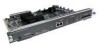
...LP CN TD TC RD RC H1981 PORT-3 PORT-1 P-3 PORT-2 PORT-0 60-Pin ports P-3 P-2 P-1 P-0 P-2 P-1` P-0 LEDs 2-18 Cisco 4000 Series Hardware Installation and Maintenance If you have cables exceeding the distances in Table 2-4, or if you use twisted-pair cables in your site...a good distribution of terminal plant wiring: • Plant cabling can couple enough energy into unshielded conductors to destroy electronic devices; Configuring Serial Connections The four-port serial network processor module ports are also a threat to electrical components and to safety. the potential ...
...LP CN TD TC RD RC H1981 PORT-3 PORT-1 P-3 PORT-2 PORT-0 60-Pin ports P-3 P-2 P-1 P-0 P-2 P-1` P-0 LEDs 2-18 Cisco 4000 Series Hardware Installation and Maintenance If you have cables exceeding the distances in Table 2-4, or if you use twisted-pair cables in your site...a good distribution of terminal plant wiring: • Plant cabling can couple enough energy into unshielded conductors to destroy electronic devices; Configuring Serial Connections The four-port serial network processor module ports are also a threat to electrical components and to safety. the potential ...
Hardware Maintenance Manual
Page 41
... connections at the modem or CSU/DSU EIA-530 The dual serial ports are DB-50 connectors. (See Figure 2-20.) These serial ports can be configured as shown in -02: for Installation 2-19
... connections at the modem or CSU/DSU EIA-530 The dual serial ports are DB-50 connectors. (See Figure 2-20.) These serial ports can be configured as shown in -02: for Installation 2-19

Hardware Maintenance Manual
Page 42
... LP DCE P-0 P-1 SERIAL (V2) PORT-1 PORT-0 H1484a Alignment groove 50-Pin serial ports Alignment groove Two LED daughter cards are configured for NRZ. Configuring the Dual Serial Module Interfaces The dual serial network processor module contains two jumpers, J4 and J5 (see Figure 2-21), which determine ...(See Figure 2-22.) For NRZ (not NRZI), the jumpers that connect pins 2 and 3 can be removed. 2-20 Cisco 4000 Series Hardware Installation and Maintenance To configure for NRZI mode on the cards. To prevent damage from stress or from ESD, do not exert force against the two LED...
... LP DCE P-0 P-1 SERIAL (V2) PORT-1 PORT-0 H1484a Alignment groove 50-Pin serial ports Alignment groove Two LED daughter cards are configured for NRZ. Configuring the Dual Serial Module Interfaces The dual serial network processor module contains two jumpers, J4 and J5 (see Figure 2-21), which determine ...(See Figure 2-22.) For NRZ (not NRZI), the jumpers that connect pins 2 and 3 can be removed. 2-20 Cisco 4000 Series Hardware Installation and Maintenance To configure for NRZI mode on the cards. To prevent damage from stress or from ESD, do not exert force against the two LED...

Hardware Maintenance Manual
Page 43
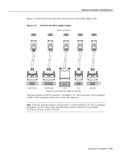
...is normally ordered with the clockrate command. and EIA-530 DTE. Nine different serial cables are not interchangeable. An error message will be configured for NRZI, move the jumpers to the position shown in Figure 2-22 using the orientation shown in Figure 2-21. Figure 2-23 ...refer to the software publications. This cable, available from your customer service representative, is not configured. For instance, if the command no dte-invert-timing was previously entered in the configuration file, then dte-invert-timing must also be manually changed. Note that the cables for the...
...is normally ordered with the clockrate command. and EIA-530 DTE. Nine different serial cables are not interchangeable. An error message will be configured for NRZI, move the jumpers to the position shown in Figure 2-22 using the orientation shown in Figure 2-21. Figure 2-23 ...refer to the software publications. This cable, available from your customer service representative, is not configured. For instance, if the command no dte-invert-timing was previously entered in the configuration file, then dte-invert-timing must also be manually changed. Note that the cables for the...

Hardware Maintenance Manual
Page 44
... clockrate command to remove the clock rate for DTE operation. This section describes how to set the clock speed with the clockrate configuration command. Setting the Four-Port Serial Module Clock Rate All DCE interfaces require a noninverted internal transmit clock signal, which is generated..., how to invert the clock to accept the internal clock signal: interface serial 0 dce-terminal-timing-enable 2-22 Cisco 4000 Series Hardware Installation and Maintenance Configuring the Four-Port Serial Module Timing (Clock) Signals All interfaces support both DTE and DCE mode, depending on the ...
... clockrate command to remove the clock rate for DTE operation. This section describes how to set the clock speed with the clockrate configuration command. Setting the Four-Port Serial Module Clock Rate All DCE interfaces require a noninverted internal transmit clock signal, which is generated..., how to invert the clock to accept the internal clock signal: interface serial 0 dce-terminal-timing-enable 2-22 Cisco 4000 Series Hardware Installation and Maintenance Configuring the Four-Port Serial Module Timing (Clock) Signals All interfaces support both DTE and DCE mode, depending on the ...

Hardware Maintenance Manual
Page 45
...module because the module will automatically discover the polarity of the interface. To enable NRZI encoding on the Four-Port Serial Module All Cisco 4000 series router serial interfaces support CRC-CCITT, a 16-bit cyclic redundancy check (CRC). Both the sender and the receiver ... to calculate a remainder or frame check sequence (FCS). The no nrzi-encoding command. The sender of interface (for NRZI encoding: router# configure terminal interface serial 0 nrzi-encoding ^Z To disable NRZI encoding on the Four-Port Serial Module All interfaces support both nonreturn to zero (NRZ...
...module because the module will automatically discover the polarity of the interface. To enable NRZI encoding on the Four-Port Serial Module All Cisco 4000 series router serial interfaces support CRC-CCITT, a 16-bit cyclic redundancy check (CRC). Both the sender and the receiver ... to calculate a remainder or frame check sequence (FCS). The no nrzi-encoding command. The sender of interface (for NRZI encoding: router# configure terminal interface serial 0 nrzi-encoding ^Z To disable NRZI encoding on the Four-Port Serial Module All interfaces support both nonreturn to zero (NRZ...


