Instruction Manual
Page 1
TFT LCD Widescreen Television Instruction Manual TFTV1524/1923/2224 Please read this manual carefully before connection and use
TFT LCD Widescreen Television Instruction Manual TFTV1524/1923/2224 Please read this manual carefully before connection and use
Instruction Manual
Page 2
... "dangerous voltage" within an equilateral triangle is located on the unit rear panel and the other than that is intended to alert the user to manual for a long time, disconnect the plug from the remote. Power Management: •• Before plugging the power cord into the AC outlet, make sure that...
... "dangerous voltage" within an equilateral triangle is located on the unit rear panel and the other than that is intended to alert the user to manual for a long time, disconnect the plug from the remote. Power Management: •• Before plugging the power cord into the AC outlet, make sure that...
Instruction Manual
Page 3
... to radio or television reception, which the receiver is connected. •• Consult the dealer or an experienced radio/TV technician for help Use of shielded cable is required to radio communications. Reverse engineering or disassembly is intended for Class B...This device must be required to comply with the instructions, may cause undesired operation. These limits are prohibited. LCD Information The LCD panel used in the manual. Copyright Protection Unauthorized copying, broadcasting, public performance, and lending of thin film transistors that this does not...
... to radio or television reception, which the receiver is connected. •• Consult the dealer or an experienced radio/TV technician for help Use of shielded cable is required to radio communications. Reverse engineering or disassembly is intended for Class B...This device must be required to comply with the instructions, may cause undesired operation. These limits are prohibited. LCD Information The LCD panel used in the manual. Copyright Protection Unauthorized copying, broadcasting, public performance, and lending of thin film transistors that this does not...
Instruction Manual
Page 13
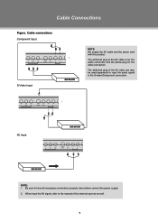
The white/red plug of the AV cable can also be used separately to the manual of the AV cable is for the audio connection and the yellow plug for the video connection. Cable Connections Figure. AV Input NOTE: 111 Be sure to have all necessary connections properly done before connect the power supply. 222 When input the AV signal, refer to input the audio signal in the S-video/Component connection. Cable connections Component Input S-Video Input NOTE: We supply the AV cable and the power cord with this product. The white/red plug of the external sources as well. 7
The white/red plug of the AV cable can also be used separately to the manual of the AV cable is for the audio connection and the yellow plug for the video connection. Cable Connections Figure. AV Input NOTE: 111 Be sure to have all necessary connections properly done before connect the power supply. 222 When input the AV signal, refer to input the audio signal in the S-video/Component connection. Cable connections Component Input S-Video Input NOTE: We supply the AV cable and the power cord with this product. The white/red plug of the external sources as well. 7
Instruction Manual
Page 19
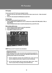
NOTE: Please see the TV section for a proper functioning. PC Function PC Function You can be automatically regulated...after, adjust "H-Pos", "V-Pos", "Clock" as well as your expectation, please perform the following steps to adjust the screen manually . 111 Enter the "Advanced" sub-menu from the SETUP menu, select "Auto" and press the left /right direction button ...select the desired sub-menu, press OK to select VGA PC Setup Menu Various features can use the unit's TFT LCD as "Phase" accordingly under the SETUP menu. 13 See the "Cable Connection" section. 222 Turn on the units ...
NOTE: Please see the TV section for a proper functioning. PC Function PC Function You can be automatically regulated...after, adjust "H-Pos", "V-Pos", "Clock" as well as your expectation, please perform the following steps to adjust the screen manually . 111 Enter the "Advanced" sub-menu from the SETUP menu, select "Auto" and press the left /right direction button ...select the desired sub-menu, press OK to select VGA PC Setup Menu Various features can use the unit's TFT LCD as "Phase" accordingly under the SETUP menu. 13 See the "Cable Connection" section. 222 Turn on the units ...
Instruction Manual
Page 20
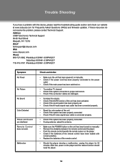
Address COBY Electronics Technical Support 56-65 Rust Street Maspeth, NY 11378 Email [email protected] ... to the power outlet. •• Check if the main power has been switched on. •• Try another TV channel •• Check if the system connection is proper and secure. •• Check if the connection cables are... If using antenna, adjust the antenna. •• Make sure the POWER button on the unit has been turned on manually. •• Remove the obstacles between the remote control and the player. •• Point the remote control towards ...
Address COBY Electronics Technical Support 56-65 Rust Street Maspeth, NY 11378 Email [email protected] ... to the power outlet. •• Check if the main power has been switched on. •• Try another TV channel •• Check if the system connection is proper and secure. •• Check if the connection cables are... If using antenna, adjust the antenna. •• Make sure the POWER button on the unit has been turned on manually. •• Remove the obstacles between the remote control and the player. •• Point the remote control towards ...
Instruction Manual
Page 22
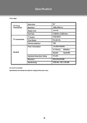
Specification TFTV 2224 TFT Panel Characteristic TV Charactoristic Active Area Resolution Display Color Pixel Pitch TV System Tuing System Antenna Impedance Power Consumption Standard Operating Temperature Range Dimension Wall Mounting 22" 1680x1050 mm 16.77 M 0.282(H) x 0.282(V)mm ATSC/NTSC FS with PLL 75Ω 110-240V 50/60Hz On Working 60W(Max) Speaker 2x(4Ω,5W) 0ºc-40ºc 527x167x444 MM VESA M4, 100 X 100 MM P/N: 907-FV15-2400-00R Specifications and manual are subject to change without prior notice. 16
Specification TFTV 2224 TFT Panel Characteristic TV Charactoristic Active Area Resolution Display Color Pixel Pitch TV System Tuing System Antenna Impedance Power Consumption Standard Operating Temperature Range Dimension Wall Mounting 22" 1680x1050 mm 16.77 M 0.282(H) x 0.282(V)mm ATSC/NTSC FS with PLL 75Ω 110-240V 50/60Hz On Working 60W(Max) Speaker 2x(4Ω,5W) 0ºc-40ºc 527x167x444 MM VESA M4, 100 X 100 MM P/N: 907-FV15-2400-00R Specifications and manual are subject to change without prior notice. 16


