

Reference Guide
Page 1
AlphaServer DS20E AlphaStation DS20E Reference Guide Order Number: ER-K8F6W-UA. D01 This manual is for managers and operators of Compaq AlphaServer DS20E / AlphaStation DS20E systems. Compaq Computer Corporation
AlphaServer DS20E AlphaStation DS20E Reference Guide Order Number: ER-K8F6W-UA. D01 This manual is for managers and operators of Compaq AlphaServer DS20E / AlphaStation DS20E systems. Compaq Computer Corporation
Reference Guide
Page 14
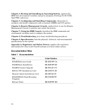
... Management Console to configure the system. Appendix A, Regulatory and Safety Notices, supplies the regulatory information for the system. Documentation Titles Table 1 Documentation Title DS20E Reference Guide DS20E Basic Installation DS20E Processor Upgrade KN311 CPU Installation Card Memory Option Installation Card H9A10/H9A15 Rack-Mounting Template Release Notes Order Number ER-K8F6W-UA ER-K8F6W...
... Management Console to configure the system. Appendix A, Regulatory and Safety Notices, supplies the regulatory information for the system. Documentation Titles Table 1 Documentation Title DS20E Reference Guide DS20E Basic Installation DS20E Processor Upgrade KN311 CPU Installation Card Memory Option Installation Card H9A10/H9A15 Rack-Mounting Template Release Notes Order Number ER-K8F6W-UA ER-K8F6W...
Reference Guide
Page 18
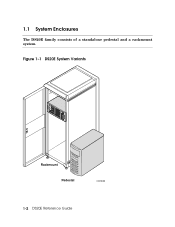
1.1 System Enclosures The DS20E family consists of a standalone pedestal and a rackmount system. Figure 1-1 DS20E System Variants Rackmount Pedestal CAT0039 1-2 DS20E Reference Guide
1.1 System Enclosures The DS20E family consists of a standalone pedestal and a rackmount system. Figure 1-1 DS20E System Variants Rackmount Pedestal CAT0039 1-2 DS20E Reference Guide
Reference Guide
Page 20
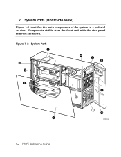
Figure 1-2 System Parts 5 4 3 6 7 8 12 9 24 1 10 1 CAT0151b 1-4 DS20E Reference Guide 1.2 System Parts (Front/Side View) Figure 1-2 identifies the main components of the system in a pedestal version. Components visible from the front and with the side panel removed are shown.
Figure 1-2 System Parts 5 4 3 6 7 8 12 9 24 1 10 1 CAT0151b 1-4 DS20E Reference Guide 1.2 System Parts (Front/Side View) Figure 1-2 identifies the main components of the system in a pedestal version. Components visible from the front and with the side panel removed are shown.
Reference Guide
Page 22
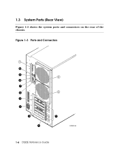
Figure 1-3 Ports and Connectors 1 10 9 8 7 6 5 4 3 2 2 3 1 CAT0019A 1-6 DS20E Reference Guide 1.3 System Parts (Rear View) Figure 1-3 shows the system ports and connectors on the rear of the chassis.
Figure 1-3 Ports and Connectors 1 10 9 8 7 6 5 4 3 2 2 3 1 CAT0019A 1-6 DS20E Reference Guide 1.3 System Parts (Rear View) Figure 1-3 shows the system ports and connectors on the rear of the chassis.
Reference Guide
Page 24
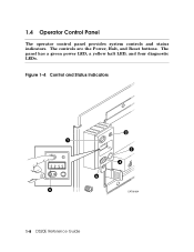
The controls are the Power, Halt, and Reset buttons. The panel has a green power LED, a yellow halt LED, and four diagnostic LEDs. 1.4 Operator Control Panel The operator control panel provides system controls and status indicators. Figure 1-4 Control and Status Indicators 1 12 34 6 2 3 4 5 CAT0018A 1-8 DS20E Reference Guide
The controls are the Power, Halt, and Reset buttons. The panel has a green power LED, a yellow halt LED, and four diagnostic LEDs. 1.4 Operator Control Panel The operator control panel provides system controls and status indicators. Figure 1-4 Control and Status Indicators 1 12 34 6 2 3 4 5 CAT0018A 1-8 DS20E Reference Guide

Reference Guide
Page 26
Figure 1-5 System Board 2 3 3 BA 1 45 6 1 1 – CPU slots (CPU0 is right slot) ™ IDE — I /O options. 1.5 System Board The system board contains slots for CPUs, memory DIMMs, and I /O slots š Floppy ˜ Memory slots › SCSI CAT0030 1-10 DS20E Reference Guide
Figure 1-5 System Board 2 3 3 BA 1 45 6 1 1 – CPU slots (CPU0 is right slot) ™ IDE — I /O options. 1.5 System Board The system board contains slots for CPUs, memory DIMMs, and I /O slots š Floppy ˜ Memory slots › SCSI CAT0030 1-10 DS20E Reference Guide

Reference Guide
Page 28
... panel connector ˜ Main logic board connector ™ Fan 0 connector š Fan 1 connector › Side cover interlock connector œ RMC switch pack (see Chapter 6) 1-12 DS20E Reference Guide
... panel connector ˜ Main logic board connector ™ Fan 0 connector š Fan 1 connector › Side cover interlock connector œ RMC switch pack (see Chapter 6) 1-12 DS20E Reference Guide
Reference Guide
Page 30
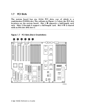
Slot 1 – supports a half-length card only. Figure 1-7 PCI Slots (Rack Orientation) 65 4 321 1-14 DS20E Reference Guide CAT0046 The callouts in Figure 1-7 show the PCI slot locations on the system board. 1.7 PCI Slots The system board has six, 64-bit PCI slots, one of which is shared with an ISA slot (ISA slot 1). Slots 2 through 6 support a full-length card. Slot 6 › is a combination PCI/ISA slot.
Slot 1 – supports a half-length card only. Figure 1-7 PCI Slots (Rack Orientation) 65 4 321 1-14 DS20E Reference Guide CAT0046 The callouts in Figure 1-7 show the PCI slot locations on the system board. 1.7 PCI Slots The system board has six, 64-bit PCI slots, one of which is shared with an ISA slot (ISA slot 1). Slots 2 through 6 support a full-length card. Slot 6 › is a combination PCI/ISA slot.

Reference Guide
Page 32
Figure 1-8 Power Supplies (Pedestal Orientation) CAT0043 NOTE: On a system with two 375-watt power supplies that are connected in a rackmount system. 1.8 Power Supplies The system comes with two power supplies, a power supply blank is the leftmost supply in a pedestal system and the topmost supply in parallel. Power supply 0 (PS0) is installed to maintain the proper airflow. 1-16 DS20E Reference Guide A third power supply can be added for redundancy.
Figure 1-8 Power Supplies (Pedestal Orientation) CAT0043 NOTE: On a system with two 375-watt power supplies that are connected in a rackmount system. 1.8 Power Supplies The system comes with two power supplies, a power supply blank is the leftmost supply in a pedestal system and the topmost supply in parallel. Power supply 0 (PS0) is installed to maintain the proper airflow. 1-16 DS20E Reference Guide A third power supply can be added for redundancy.
Reference Guide
Page 34
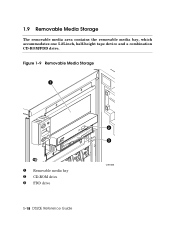
Figure 1-9 Removable Media Storage 1 – Removable media bay — CD-ROM drive ˜ FDD drive 1-18 DS20E Reference Guide 2 3 CAT0050 1.9 Removable Media Storage The removable media area contains the removable media bay, which accommodates one 5.25-inch, half-height tape device and a combination CD-ROM/FDD drive.
Figure 1-9 Removable Media Storage 1 – Removable media bay — CD-ROM drive ˜ FDD drive 1-18 DS20E Reference Guide 2 3 CAT0050 1.9 Removable Media Storage The removable media area contains the removable media bay, which accommodates one 5.25-inch, half-height tape device and a combination CD-ROM/FDD drive.
Reference Guide
Page 36
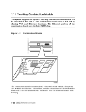
The combination board saves a PCI slot by sharing VGA and Ethernet functions. You can be installed in PCI slot 1. The module provides connections for the VGA (Video Permedia 2) and the Ethernet (NIC functions). The Ethernet portion of the combination board uses the Intel 82558 chip. Figure 1-11 Combination Module CAT0042 The combination module features 2D/3D video (with 4 MB VRAM), along with 10/100 MB Fast Ethernet. 1.11 Two-Way Combination Module The system supports an optional two-way combination module that can order the module from Compaq. 1-20 DS20E Reference Guide
The combination board saves a PCI slot by sharing VGA and Ethernet functions. You can be installed in PCI slot 1. The module provides connections for the VGA (Video Permedia 2) and the Ethernet (NIC functions). The Ethernet portion of the combination board uses the Intel 82558 chip. Figure 1-11 Combination Module CAT0042 The combination module features 2D/3D video (with 4 MB VRAM), along with 10/100 MB Fast Ethernet. 1.11 Two-Way Combination Module The system supports an optional two-way combination module that can order the module from Compaq. 1-20 DS20E Reference Guide
Reference Guide
Page 40
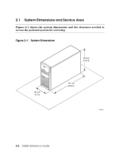
2.1 System Dimensions and Service Area Figure 2-1 shows the system dimensions and the clearance needed to access the pedestal system for servicing. Figure 2-1 System Dimensions 44.8 cm (17.6 in) 22.1 cm (8.7 in) 74.7 cm (29.4 in) PK3212 2-2 DS20E Reference Guide
2.1 System Dimensions and Service Area Figure 2-1 shows the system dimensions and the clearance needed to access the pedestal system for servicing. Figure 2-1 System Dimensions 44.8 cm (17.6 in) 22.1 cm (8.7 in) 74.7 cm (29.4 in) PK3212 2-2 DS20E Reference Guide
Reference Guide
Page 42
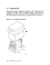
Instructions for unpacking are also in the accessories tray –. Figure 2-3 Unpacking the Shipment 1 CAT0044a 2-4 DS20E Reference Guide The system chassis is shipped in a single box. 2.3 Shipment Box The pedestal system is completely assembled, with other accessories. An installation document and this reference guide are in the tray, along with all modules installed.
Instructions for unpacking are also in the accessories tray –. Figure 2-3 Unpacking the Shipment 1 CAT0044a 2-4 DS20E Reference Guide The system chassis is shipped in a single box. 2.3 Shipment Box The pedestal system is completely assembled, with other accessories. An installation document and this reference guide are in the tray, along with all modules installed.
Reference Guide
Page 44
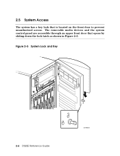
The removable media devices and the system control panel are accessible through an upper front door that is located on the front door to prevent unauthorized access. Figure 2-5 System Lock and Key 2-6 DS20E Reference Guide CAT0024 2.5 System Access The system has a key lock that opens by sliding down the lock latch as shown in Figure 2-5.
The removable media devices and the system control panel are accessible through an upper front door that is located on the front door to prevent unauthorized access. Figure 2-5 System Lock and Key 2-6 DS20E Reference Guide CAT0024 2.5 System Access The system has a key lock that opens by sliding down the lock latch as shown in Figure 2-5.
Reference Guide
Page 48
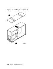
Figure 2-7 Installing the Lower Panel 2 1 PK3215 2-10 DS20E Reference Guide
Figure 2-7 Installing the Lower Panel 2 1 PK3215 2-10 DS20E Reference Guide
Reference Guide
Page 50
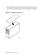
Insert a thumbscrew into the tab on the top of the unit. Figure 2-8 Installing the Upper Panel PK3203 2-12 DS20E Reference Guide Slide the panel to the left on the panel and insert it in the box and tighten. 5. See Figure 2- 8. Place the upper panel with the painted surface up and the large tabs to the right.
Insert a thumbscrew into the tab on the top of the unit. Figure 2-8 Installing the Upper Panel PK3203 2-12 DS20E Reference Guide Slide the panel to the left on the panel and insert it in the box and tighten. 5. See Figure 2- 8. Place the upper panel with the painted surface up and the large tabs to the right.
Reference Guide
Page 52
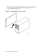
7. Figure 2-10 Installing the Side Access Cover 1 PK3205 2-14 DS20E Reference Guide See Figure 2-10. Slide the cover forward and secure it with the captive screw –. Install the side access cover by inserting the cover tabs (4 top, 4 bottom) into the slots in the chassis.
7. Figure 2-10 Installing the Side Access Cover 1 PK3205 2-14 DS20E Reference Guide See Figure 2-10. Slide the cover forward and secure it with the captive screw –. Install the side access cover by inserting the cover tabs (4 top, 4 bottom) into the slots in the chassis.
Reference Guide
Page 56
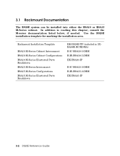
... H9A10 M-Series Cabinet Interconnect H9A10 M-Series Cabinet Configurations H9A10 M-Series Illustrated Parts Breakdown H9A15 M-Series Interconnect H9A15 M-Series Configurations H9A15 M-Series Illustrated Parts Breakdown EK-DS20E-TP (included in 3XBA56R-RC/RD/RA) B-IC-H9A10-5-DBM B-IB-H9A10-5-DBM EK-H9A10-IP B-IC-H9A15-3-DBM B-IB-H9A15-3-DBM EK-H9A15-IP...
... H9A10 M-Series Cabinet Interconnect H9A10 M-Series Cabinet Configurations H9A10 M-Series Illustrated Parts Breakdown H9A15 M-Series Interconnect H9A15 M-Series Configurations H9A15 M-Series Illustrated Parts Breakdown EK-DS20E-TP (included in 3XBA56R-RC/RD/RA) B-IC-H9A10-5-DBM B-IB-H9A10-5-DBM EK-H9A10-IP B-IC-H9A15-3-DBM B-IB-H9A15-3-DBM EK-H9A15-IP...
Reference Guide
Page 58
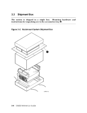
Figure 3-2 Rackmount System Shipment Box 1 CAT0011a 3-4 DS20E Reference Guide 3.3 Shipment Box The system is shipped in the accessories tray –. Mounting hardware and instructions for unpacking are in a single box.
Figure 3-2 Rackmount System Shipment Box 1 CAT0011a 3-4 DS20E Reference Guide 3.3 Shipment Box The system is shipped in the accessories tray –. Mounting hardware and instructions for unpacking are in a single box.