HP USB Digital Drive
Page 3
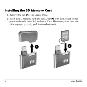
Insert the SD memory card into the SD slot 2 with the notched corner positioned on the lower left as shown. If the SD memory card does not slide in properly, gently pull it out and reinsert it. 2 User Guide Remove the cap 1 of the Digital Drive. 2. Installing the SD Memory Card 1.
Insert the SD memory card into the SD slot 2 with the notched corner positioned on the lower left as shown. If the SD memory card does not slide in properly, gently pull it out and reinsert it. 2 User Guide Remove the cap 1 of the Digital Drive. 2. Installing the SD Memory Card 1.
Memory Modules - Windows Vista
Page 2
Contents Adding or replacing memory modules Adding a memory module to the expansion memory module slot 2 Upgrading a memory module in the primary memory module slot 7 Index Memory Modules ii
Contents Adding or replacing memory modules Adding a memory module to the expansion memory module slot 2 Upgrading a memory module in the primary memory module slot 7 Index Memory Modules ii

Memory Modules - Windows Vista
Page 3
... are discharged of static electricity by replacing the existing memory module in the primary memory module slot or the expansion memory module slot. Å WARNING: To reduce the risk of electric shock and damage to the equipment, unplug the power cord and remove all batteries before installing a memory module. Ä CAUTION: Electrostatic discharge (ESD) can be...
... are discharged of static electricity by replacing the existing memory module in the primary memory module slot or the expansion memory module slot. Å WARNING: To reduce the risk of electric shock and damage to the equipment, unplug the power cord and remove all batteries before installing a memory module. Ä CAUTION: Electrostatic discharge (ESD) can be...
Memory Modules - Windows Vista
Page 4
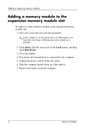
...battery from the AC outlet. 6. Unplug the power cord from the computer. 2 Memory Modules Disconnect all open programs. ✎ If the computer is in the Sleep state or in the expansion memory module slot: 1. Save your work and close all external devices connected to the computer. ..., and then click Shut Down. 3. Turn the computer upside down on a flat surface. 7. Adding or replacing memory modules Adding a memory module to the expansion memory module slot To replace or add a memory module in Hibernation, you must first exit Sleep or Hibernation before shutdown is possible. 2.
...battery from the AC outlet. 6. Unplug the power cord from the computer. 2 Memory Modules Disconnect all open programs. ✎ If the computer is in the Sleep state or in the expansion memory module slot: 1. Save your work and close all external devices connected to the computer. ..., and then click Shut Down. 3. Turn the computer upside down on a flat surface. 7. Adding or replacing memory modules Adding a memory module to the expansion memory module slot To replace or add a memory module in Hibernation, you must first exit Sleep or Hibernation before shutdown is possible. 2.
Memory Modules - Windows Vista
Page 6
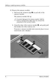
Pull away the retention clips 1 on each side of the memory module. Adding or replacing memory modules 10. Do not touch the components of the memory module. To protect a memory module after removal, place it in an electrostatic-safe container. 4 Memory Modules Grasp the edge of the memory module 2, and gently pull the module out of the memory slot. Remove the memory module: a. b. The memory module tilts up. Ä To prevent damage to the memory module, hold the memory module by the edges only.
Pull away the retention clips 1 on each side of the memory module. Adding or replacing memory modules 10. Do not touch the components of the memory module. To protect a memory module after removal, place it in an electrostatic-safe container. 4 Memory Modules Grasp the edge of the memory module 2, and gently pull the module out of the memory slot. Remove the memory module: a. b. The memory module tilts up. Ä To prevent damage to the memory module, hold the memory module by the edges only.
Memory Modules - Windows Vista
Page 7
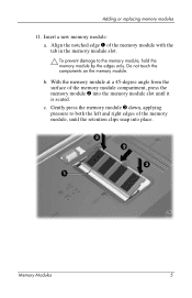
..., applying pressure to both the left and right edges of the memory module with the tab in the memory module slot. Ä To prevent damage to the memory module, hold the memory module by the edges only. Memory Modules 5 b. Align the notched edge 1 of the memory module, until it is seated. Do not touch the components on...
..., applying pressure to both the left and right edges of the memory module with the tab in the memory module slot. Ä To prevent damage to the memory module, hold the memory module by the edges only. Memory Modules 5 b. Align the notched edge 1 of the memory module, until it is seated. Do not touch the components on...
Memory Modules - Windows Vista
Page 9
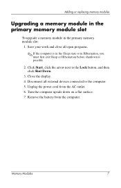
...cord from the computer. Remove the battery from the AC outlet. 6. Memory Modules 7 Turn the computer upside down on a flat surface. 7. Adding or replacing memory modules Upgrading a memory module in the primary memory module slot To upgrade a memory module in Hibernation, you must first exit Sleep or Hibernation before shutdown ...possible. 2. Disconnect all open programs. ✎ If the computer is in the Sleep state or in the primary memory module slot: 1. Close the display. 4. Save your work and close all external devices connected to the Lock button, and then click Shut Down...
...cord from the computer. Remove the battery from the AC outlet. 6. Memory Modules 7 Turn the computer upside down on a flat surface. 7. Adding or replacing memory modules Upgrading a memory module in the primary memory module slot To upgrade a memory module in Hibernation, you must first exit Sleep or Hibernation before shutdown ...possible. 2. Disconnect all open programs. ✎ If the computer is in the Sleep state or in the primary memory module slot: 1. Close the display. 4. Save your work and close all external devices connected to the Lock button, and then click Shut Down...
Memory Modules - Windows Vista
Page 12
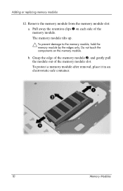
Remove the memory module from the memory module slot: a. To protect a memory module after removal, place it in an electrostatic-safe container. 10 Memory Modules Do not touch the components on each side of the memory module slot. Grasp the edge of the memory module 2, and gently pull the module out of the memory module. Pull away the retention clips 1 on the memory module. b. Adding or replacing memory modules 12. The memory module tilts up. Ä To prevent damage to the memory module, hold the memory module by the edges only.
Remove the memory module from the memory module slot: a. To protect a memory module after removal, place it in an electrostatic-safe container. 10 Memory Modules Do not touch the components on each side of the memory module slot. Grasp the edge of the memory module 2, and gently pull the module out of the memory module. Pull away the retention clips 1 on the memory module. b. Adding or replacing memory modules 12. The memory module tilts up. Ä To prevent damage to the memory module, hold the memory module by the edges only.
Memory Modules - Windows Vista
Page 13
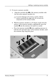
c. Align the notched edge 1 of the memory module with the tab in the memory module slot. Ä To prevent damage to both the left and right edges of the memory module compartment, press the module 2 into the memory slot until the retention clips snap into place. To insert a memory module: a. With the memory module at a 45-degree angle from...
c. Align the notched edge 1 of the memory module with the tab in the memory module slot. Ä To prevent damage to both the left and right edges of the memory module compartment, press the module 2 into the memory slot until the retention clips snap into place. To insert a memory module: a. With the memory module at a 45-degree angle from...
Notebook Tour - Windows Vista
Page 15
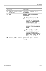
... the computer only on and off during routine operation. 8 Accessory battery connector Connects an optional accessory battery. Components Component Description 6 Expansion memory module compartment 7 Vent Contains the expansion memory module slot. Do not allow another hard surface, such as an adjoining optional printer, or a soft surface, such as pillows or thick rugs or... computer fan starts up automatically to cycle on a hard, flat surface. Enables airflow to cool internal components. Ä To prevent overheating, do not obstruct vents. Notebook Tour 1-13
... the computer only on and off during routine operation. 8 Accessory battery connector Connects an optional accessory battery. Components Component Description 6 Expansion memory module compartment 7 Vent Contains the expansion memory module slot. Do not allow another hard surface, such as an adjoining optional printer, or a soft surface, such as pillows or thick rugs or... computer fan starts up automatically to cycle on a hard, flat surface. Enables airflow to cool internal components. Ä To prevent overheating, do not obstruct vents. Notebook Tour 1-13

Notebook Tour - Windows Vista
Page 24
...jack 1-10 S security cable slot 1-10 serial number, computer 1-16 service tag 1-16 slots memory 1-13 security cable 1-10 ...specifications operating environment 2-1 rated input power 2-2 switches display 1-5 identifying 1-5 T temperature specifications 2-1 TouchPad 1-4 traveling with computer environmental specifications 2-2 modem approval label 1-17 wireless certification labels 1-17 U USB ports, identifying 1-9, 1-11 V vent 1-11, 1-13 volume buttons 1-6 W Windows applications key 1-7 Windows logo key 1-7 wireless antennae 1-14 wireless button 1-6 Notebook...
...jack 1-10 S security cable slot 1-10 serial number, computer 1-16 service tag 1-16 slots memory 1-13 security cable 1-10 ...specifications operating environment 2-1 rated input power 2-2 switches display 1-5 identifying 1-5 T temperature specifications 2-1 TouchPad 1-4 traveling with computer environmental specifications 2-2 modem approval label 1-17 wireless certification labels 1-17 U USB ports, identifying 1-9, 1-11 V vent 1-11, 1-13 volume buttons 1-6 W Windows applications key 1-7 Windows logo key 1-7 wireless antennae 1-14 wireless button 1-6 Notebook...
PC Cards - Windows Vista
Page 3
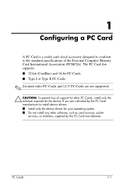
...; CAUTION: To prevent loss of the Personal Computer Memory Card International Association (PCMCIA). PC Cards 1-1 The PC Card slot supports ■ 32-bit (CardBus) and 16-bit PC Cards. ■ Type I or Type II PC Cards. ✎ Zoomed video PC Cards and 12-V PC Cards are instructed by the PC Card manufacturer to the standard specifications of support for...
...; CAUTION: To prevent loss of the Personal Computer Memory Card International Association (PCMCIA). PC Cards 1-1 The PC Card slot supports ■ 32-bit (CardBus) and 16-bit PC Cards. ■ Type I or Type II PC Cards. ✎ Zoomed video PC Cards and 12-V PC Cards are instructed by the PC Card manufacturer to the standard specifications of support for...

HP Compaq nx7300 and nx7400 Notebook PC Maintenance and Service Guide
Page 26
... Table 1-8. Product Description The external components on the bottom of the computer are shown below and described in the battery bay. Memory module compartment Contains one memory slot that supports replaceable memory modules. Accessory battery connector Connects an optional HP Ultra-Capacity Battery or HP Extended Life Battery. Exhaust vents Provides airflow to an...
... Table 1-8. Product Description The external components on the bottom of the computer are shown below and described in the battery bay. Memory module compartment Contains one memory slot that supports replaceable memory modules. Accessory battery connector Connects an optional HP Ultra-Capacity Battery or HP Extended Life Battery. Exhaust vents Provides airflow to an...
HP Compaq nx7300 and nx7400 Notebook PC Maintenance and Service Guide
Page 62
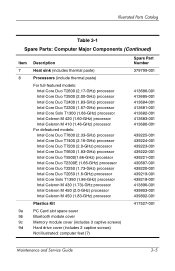
... (1.86-GHz) processor Intel Celeron M 430 (1.73)-GHz processor Intel Celeron M 450 (2.0-GHz) processor Intel Celeron M 450 (1.83-GHz) processor Plastics Kit PC Card slot space saver Bluetooth module cover Memory module cover (includes 3 captive screws) Hard drive cover (includes 2 captive screws) Not illustrated: computer feet (7) Spare Part Number 379799-001 413686-001...
... (1.86-GHz) processor Intel Celeron M 430 (1.73)-GHz processor Intel Celeron M 450 (2.0-GHz) processor Intel Celeron M 450 (1.83-GHz) processor Plastics Kit PC Card slot space saver Bluetooth module cover Memory module cover (includes 3 captive screws) Hard drive cover (includes 2 captive screws) Not illustrated: computer feet (7) Spare Part Number 379799-001 413686-001...
HP Compaq nx7300 and nx7400 Notebook PC Maintenance and Service Guide
Page 72
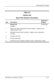
Illustrated Parts Catalog Item 1 2 3 4 5 Table 3-2 Plastics Kit Spare Part Number Information Description Spare Part Number Plastics Kit Includes: 417527-001 Memory module compartment cover (includes 1 captive screw, captured by a C-clip) Bluetooth module cover (includes 1 captive screw, captured by a C clip) Computer feet (8) PC Card slot bezel Hard drive cover (includes 2 captive screws, captured by C-clips) Maintenance and Service Guide 3-15
Illustrated Parts Catalog Item 1 2 3 4 5 Table 3-2 Plastics Kit Spare Part Number Information Description Spare Part Number Plastics Kit Includes: 417527-001 Memory module compartment cover (includes 1 captive screw, captured by a C-clip) Bluetooth module cover (includes 1 captive screw, captured by a C clip) Computer feet (8) PC Card slot bezel Hard drive cover (includes 2 captive screws, captured by C-clips) Maintenance and Service Guide 3-15
HP Compaq nx7300 and nx7400 Notebook PC Maintenance and Service Guide
Page 241
... removal 5-35 S safeguarding your data B-2 scheduling backups Windows Vista C-5 Screw Kit, spare part number 3-20, 3-27, 3-28, A-1 security cable slot 1-11 serial number 3-1, 5-2 service considerations 4-2 speakers 1-16 specifications CD-ROM drive 6-12 computer 6-1 DVD/CD-RW Combo Drive 6-9, 6-11 DVD&#...177;RW and CD-RW Combo Drive 6-7, 6-9, 6-12 DVD-ROM drive 6-11 hard drive 6-5 I/O addresses 6-17 interrupts 6-15 memory map 6-20 optical drive 6-7, 6-9, 6-11, 6-12 system DMA 6-14 static shielding materials 4-8 stringent security 1-5 switch cover removal 5-36 spare part number...
... removal 5-35 S safeguarding your data B-2 scheduling backups Windows Vista C-5 Screw Kit, spare part number 3-20, 3-27, 3-28, A-1 security cable slot 1-11 serial number 3-1, 5-2 service considerations 4-2 speakers 1-16 specifications CD-ROM drive 6-12 computer 6-1 DVD/CD-RW Combo Drive 6-9, 6-11 DVD&#...177;RW and CD-RW Combo Drive 6-7, 6-9, 6-12 DVD-ROM drive 6-11 hard drive 6-5 I/O addresses 6-17 interrupts 6-15 memory map 6-20 optical drive 6-7, 6-9, 6-11, 6-12 system DMA 6-14 static shielding materials 4-8 stringent security 1-5 switch cover removal 5-36 spare part number...


