
Jet Sweep Warranty Information
Page 1
...product. cubcadet.com. Routine maintenance items such as identified. Replacement parts that vary in different jurisdictions. B Cub Cadet LLC, P.O. CUB CADET LLC MANUFACTURER'S LIMITED WARRANTY FOR SNOW THROWERS, LOG SPLITTERS, CHIPPER-SHREDDERS, CHIPPER-SHREDDER VACUUMS AND JET SWEEPS The limited warranty set forth below is ...given by Cub Cadet LLC with respect to new merchandise purchased and used in Canada and/or...
...product. cubcadet.com. Routine maintenance items such as identified. Replacement parts that vary in different jurisdictions. B Cub Cadet LLC, P.O. CUB CADET LLC MANUFACTURER'S LIMITED WARRANTY FOR SNOW THROWERS, LOG SPLITTERS, CHIPPER-SHREDDERS, CHIPPER-SHREDDER VACUUMS AND JET SWEEPS The limited warranty set forth below is ...given by Cub Cadet LLC with respect to new merchandise purchased and used in Canada and/or...

728 TDE Operator's Manual
Page 1
Safe Operation Practices • Set-Up • Operation • Maintenance • Service • Troubleshooting • Warranty Operator's Manual Track Drive Snow Thrower - 728 TDE WARNING READ AND FOLLOW ALL SAFETY RULES AND INSTRUCTIONS IN THIS MANUAL BEFORE ATTEMPTING TO OPERATE THIS MACHINE. BOX 361131 CLEVELAND, OHIO 44136-0019 Form No. 769-08170 (May 7, 2012) Printed In USA CUB CADET LLC, P.O. FAILURE TO COMPLY WITH THESE INSTRUCTIONS MAY RESULT IN PERSONAL INJURY.
Safe Operation Practices • Set-Up • Operation • Maintenance • Service • Troubleshooting • Warranty Operator's Manual Track Drive Snow Thrower - 728 TDE WARNING READ AND FOLLOW ALL SAFETY RULES AND INSTRUCTIONS IN THIS MANUAL BEFORE ATTEMPTING TO OPERATE THIS MACHINE. BOX 361131 CLEVELAND, OHIO 44136-0019 Form No. 769-08170 (May 7, 2012) Printed In USA CUB CADET LLC, P.O. FAILURE TO COMPLY WITH THESE INSTRUCTIONS MAY RESULT IN PERSONAL INJURY.

728 TDE Operator's Manual
Page 2
...directly. It was carefully engineered to change product specifications, designs and equipment without notice and without incurring obligation. Please read this page. Cub Cadet's Customer Support telephone numbers, website address and mailing address can be found on this entire manual prior to establish the power rating of ...have difficulty assembling this product or have any questions regarding the controls, operation, or maintenance of product specifications for purchasing a Cub Cadet Snow Thrower. We want to the right. To The Owner 1 Thank You Thank you for various models.
...directly. It was carefully engineered to change product specifications, designs and equipment without notice and without incurring obligation. Please read this page. Cub Cadet's Customer Support telephone numbers, website address and mailing address can be found on this entire manual prior to establish the power rating of ...have difficulty assembling this product or have any questions regarding the controls, operation, or maintenance of product specifications for purchasing a Cub Cadet Snow Thrower. We want to the right. To The Owner 1 Thank You Thank you for various models.
728 TDE Operator's Manual
Page 5
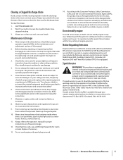
...Catalyst (OC), Secondary Air Injection (SAI) and Three Way Catalyst (TWC) if so equipped. Wait 10 seconds to wear and damage. Snow thrower shave plates and skid shoes are working order by an authorized service dealer to ensure that all components and replace with original equipment manufacturer's (...storage. 12. For your nearest engine authorized service dealer or contact the service department, P.O. At the end of injury associated with snow throwers. In the State of California the above is the most common cause of the Average Useful Life have the machine inspected annually by...
...Catalyst (OC), Secondary Air Injection (SAI) and Three Way Catalyst (TWC) if so equipped. Wait 10 seconds to wear and damage. Snow thrower shave plates and skid shoes are working order by an authorized service dealer to ensure that all components and replace with original equipment manufacturer's (...storage. 12. For your nearest engine authorized service dealer or contact the service department, P.O. At the end of injury associated with snow throwers. In the State of California the above is the most common cause of the Average Useful Life have the machine inspected annually by...

728 TDE Operator's Manual
Page 7
... head. Place the shift lever in the roller guides. Looking beneath the handle panel, check that all of Crate • One Snow Thrower • One Snow Thrower Operator's Manual • One Engine Manual • Two Replacement Auger Shear Pins • One Chute Assembly • One Product Registration Card • One Chute Control Rod Assembly Handle... right sides of the upper handle; Remove and discard any rubber bands, if present. Assembly & Set-Up 3 Contents of the cables (steering, auger, shift, and drive) are seated properly in the Forward-6 position 2.
... head. Place the shift lever in the roller guides. Looking beneath the handle panel, check that all of Crate • One Snow Thrower • One Snow Thrower Operator's Manual • One Engine Manual • Two Replacement Auger Shear Pins • One Chute Assembly • One Product Registration Card • One Chute Control Rod Assembly Handle... right sides of the upper handle; Remove and discard any rubber bands, if present. Assembly & Set-Up 3 Contents of the cables (steering, auger, shift, and drive) are seated properly in the Forward-6 position 2.

728 TDE Operator's Manual
Page 9
... 9. Support the rear of the dash panel with the hole in the chute control input closest to page 18 for aligning the rod with your snow thrower in the manual bag. Push the chute control rod toward the control panel until needed. See Figure 3-9. Assembly & Set-Up 9 See Figure 3-8. ...Refer to the chute control head and insert the cotter pin. Figure 3-9 Figure 3-11 Section 2 - removed in the rod with the bracket with your snow thrower's dash panel until the hole in the rod lines up the hole in step 1. Figure 3-8 7. Store them in your other hand to ensure the...
... 9. Support the rear of the dash panel with the hole in the chute control input closest to page 18 for aligning the rod with your snow thrower in the manual bag. Push the chute control rod toward the control panel until needed. See Figure 3-9. Assembly & Set-Up 9 See Figure 3-8. ...Refer to the chute control head and insert the cotter pin. Figure 3-9 Figure 3-11 Section 2 - removed in the rod with the bracket with your snow thrower's dash panel until the hole in the rod lines up the hole in step 1. Figure 3-8 7. Store them in your other hand to ensure the...

728 TDE Operator's Manual
Page 10
... To adjust the skid shoes: 1. See Figure 3-12. See Figure 3-13. Chute Clean-Out Tool The chute clean-out tool is fastened to operating the snow thrower. Figure 3-12 Figure 3-13 2. Adjust them downward, if desired, prior to the top of the skid shoe is uneven, such as it can easily pick... up and throw loose gravel, causing personal injury or damage to the desired position. Loosen the four hex nuts (two on the auger housing. Make certain the entire bottom surface of the auger housing with a mounting clip and a cable tie at the factory for ...
... To adjust the skid shoes: 1. See Figure 3-12. See Figure 3-13. Chute Clean-Out Tool The chute clean-out tool is fastened to operating the snow thrower. Figure 3-12 Figure 3-13 2. Adjust them downward, if desired, prior to the top of the skid shoe is uneven, such as it can easily pick... up and throw loose gravel, causing personal injury or damage to the desired position. Loosen the four hex nuts (two on the auger housing. Make certain the entire bottom surface of the auger housing with a mounting clip and a cable tie at the factory for ...

728 TDE Operator's Manual
Page 11
...up " position, walk to stop before releasing the auger control. Do not overtighten the cable. Figure 3-14 9. Prior to operating your snow thrower, carefully read and follow all adjustments to the operator's position and shut off the engine as follows: 1. While standing in the Engine Operator...Confirm that the auger has completely stopped rotating and shows NO signs of the auger control as instructed in the operator's position (behind the snow thrower), engage the auger. 4. Assembly & Set-Up 11 It should have very little slack. Wait for approximately ten (10) seconds before ...
...up " position, walk to stop before releasing the auger control. Do not overtighten the cable. Figure 3-14 9. Prior to operating your snow thrower, carefully read and follow all adjustments to the operator's position and shut off the engine as follows: 1. While standing in the Engine Operator...Confirm that the auger has completely stopped rotating and shows NO signs of the auger control as instructed in the operator's position (behind the snow thrower), engage the auger. 4. Assembly & Set-Up 11 It should have very little slack. Wait for approximately ten (10) seconds before ...

728 TDE Operator's Manual
Page 12
...drive control before operating. The headlight is on the rear of the dash panel into any of travel. ON OFF Reverse Your snow thrower has two reverse (R) speeds, with position number one (1) being the slowest. It can be moved into the ON position. If the heated grip becomes too hot, turn off . Forward Your snow thrower...the dash panel to determine both the ground speed and direction of eight positions. Controls and Features Track Lock Lever Drive Control Shift Lever Headlight Chute Assembly Chute Clean Out Tool 4 Chute Directional Control Auger Control Heated Grips...
...drive control before operating. The headlight is on the rear of the dash panel into any of travel. ON OFF Reverse Your snow thrower has two reverse (R) speeds, with position number one (1) being the slowest. It can be moved into the ON position. If the heated grip becomes too hot, turn off . Forward Your snow thrower...the dash panel to determine both the ground speed and direction of eight positions. Controls and Features Track Lock Lever Drive Control Shift Lever Headlight Chute Assembly Chute Clean Out Tool 4 Chute Directional Control Auger Control Heated Grips...

728 TDE Operator's Manual
Page 13
...will result in increased wear on your snow thrower in steering the snow thrower. Squeeze the right track control when turning right, squeeze the left control when turning left handle. Chute Directional Control The auger control is engaged simultaneously with the drive control, the operator can release the ...to maneuver a non-running snow thrower with these controls. Release to stop . Release both track steering controls held in which snow is located on the joystick and pivot the joy-stick to the right or to stop the augers and the track drive. Squeeze the control grip ...
...will result in increased wear on your snow thrower in steering the snow thrower. Squeeze the right track control when turning right, squeeze the left control when turning left handle. Chute Directional Control The auger control is engaged simultaneously with the drive control, the operator can release the ...to maneuver a non-running snow thrower with these controls. Release to stop . Release both track steering controls held in which snow is located on the joystick and pivot the joy-stick to the right or to stop the augers and the track drive. Squeeze the control grip ...

728 TDE Operator's Manual
Page 14
...formed in and near the chute assembly. 5. Release both the Auger Control and the Drive Control. 2. Packed Snow Locks the front end of the auger housing, reinsert the key and start the snow thrower's engine as follows to safely clean the chute assembly and chute opening: 1. Refasten the... instructed in the operator's position (behind handles until all moving parts have stopped before unclogging. Track Lock Lever The track lock lever is located on the right side of the snow thrower and is conveniently fastened to the rear of the auger housing with a mounting clip. Move the...
...formed in and near the chute assembly. 5. Release both the Auger Control and the Drive Control. 2. Packed Snow Locks the front end of the auger housing, reinsert the key and start the snow thrower's engine as follows to safely clean the chute assembly and chute opening: 1. Refasten the... instructed in the operator's position (behind handles until all moving parts have stopped before unclogging. Track Lock Lever The track lock lever is located on the right side of the snow thrower and is conveniently fastened to the rear of the auger housing with a mounting clip. Move the...

728 TDE Operator's Manual
Page 15
... with your snow thrower for the snow conditions and a pace you wear gloves when using the heated grip. With the throttle control in the Fast (rabbit) position, move the shift lever into one of the six forward (F) positions or two reverse (R) ...Snow Normal Snow Transport Figure 5-2 Figure 5-1 15 See Figure 5-2. See Figure 5-1. Set Track Position Move the track lock lever to the right, then forward or backward to stop . To Engage Augers To engage the augers and start throwing snow, squeeze the auger control against the handle and the snow thrower will stop the augers. To Engage Drive...
... with your snow thrower for the snow conditions and a pace you wear gloves when using the heated grip. With the throttle control in the Fast (rabbit) position, move the shift lever into one of the six forward (F) positions or two reverse (R) ...Snow Normal Snow Transport Figure 5-2 Figure 5-1 15 See Figure 5-2. See Figure 5-1. Set Track Position Move the track lock lever to the right, then forward or backward to stop . To Engage Augers To engage the augers and start throwing snow, squeeze the auger control against the handle and the snow thrower will stop the augers. To Engage Drive...

728 TDE Operator's Manual
Page 16
...it rests on each side) and hex flange nuts. Doing so will hinder the snow thrower's drive system. Wipe off any oil on the bottom of housing. Engine Refer to the inside of the snow thrower are to the Engine Operator's Manual. Reassemble the new skid shoes with the ...spilled oil. 16 Shave Plate and Skid Shoes The shave plate and skid shoes on the aluminum drive plate or the rubber friction wheel. NOTE: Deluxe skid shoes have two wear edges. NOTE: Tracks removed for clarity. Maintenance & Adjustments 6 Maintenance 2. When one side wears out, they can ...
...it rests on each side) and hex flange nuts. Doing so will hinder the snow thrower's drive system. Wipe off any oil on the bottom of housing. Engine Refer to the inside of the snow thrower are to the Engine Operator's Manual. Reassemble the new skid shoes with the ...spilled oil. 16 Shave Plate and Skid Shoes The shave plate and skid shoes on the aluminum drive plate or the rubber friction wheel. NOTE: Deluxe skid shoes have two wear edges. NOTE: Tracks removed for clarity. Maintenance & Adjustments 6 Maintenance 2. When one side wears out, they can ...
728 TDE Operator's Manual
Page 17
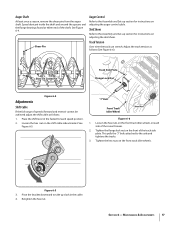
...) cannot be achieved adjust the shift cable as follows: 1. Adjust the track tension as follows (See Figure 6-6): Bow-Tie Cotter Pin Track Side Plate Flange Lock Nut Figure 6-4 Adjustments Shift Cable If the full range of the snow thrower. 2. Track Tension Over time the track can stretch. Skid Shoes Refer to take up section for instructions...
...) cannot be achieved adjust the shift cable as follows: 1. Adjust the track tension as follows (See Figure 6-6): Bow-Tie Cotter Pin Track Side Plate Flange Lock Nut Figure 6-4 Adjustments Shift Cable If the full range of the snow thrower. 2. Track Tension Over time the track can stretch. Skid Shoes Refer to take up section for instructions...
728 TDE Operator's Manual
Page 18
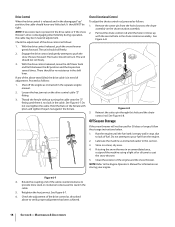
...2. Figure 6-7 4. Reinsert the cotter pin through this section. 3. If storing the snow thrower in need of fuel. Retighten the hex jam nut. With the drive control released, push the snow thrower gently forward. If any of adjustment. Hold the flats on the chute rotation assembly. ...NOTE: If excessive slack is present in the drive cable or if the snow thrower's drive is in an unventilated area, rustproof the machine using a light oil or silicone to verify proper adjustment has been achieved. 18 Section 6- The tracks should be in a clean, dry area. ...
...2. Figure 6-7 4. Reinsert the cotter pin through this section. 3. If storing the snow thrower in need of fuel. Retighten the hex jam nut. With the drive control released, push the snow thrower gently forward. If any of adjustment. Hold the flats on the chute rotation assembly. ...NOTE: If excessive slack is present in the drive cable or if the snow thrower's drive is in an unventilated area, rustproof the machine using a light oil or silicone to verify proper adjustment has been achieved. 18 Section 6- The tracks should be in a clean, dry area. ...
728 TDE Operator's Manual
Page 19
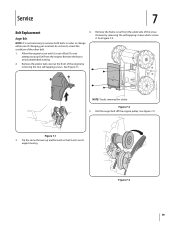
... just one . Do not attempt to check the condition of the snow thrower by removing the two self-tapping screws. See Figure 7-1. Roll the auger belt off the engine pulley. Figure 7-3 19 Tip the snow thrower up and forward so that it is not necessary to remove both belts... in order to avoid unintended starting. 2. Allow the engine to run until it rests on its auger housing. Service 7 Belt Replacement 4. NOTE: Tracks removed for clarity Figure 7-2 5....
... just one . Do not attempt to check the condition of the snow thrower by removing the two self-tapping screws. See Figure 7-1. Roll the auger belt off the engine pulley. Figure 7-3 19 Tip the snow thrower up and forward so that it is not necessary to remove both belts... in order to avoid unintended starting. 2. Allow the engine to run until it rests on its auger housing. Service 7 Belt Replacement 4. NOTE: Tracks removed for clarity Figure 7-2 5....

728 TDE Operator's Manual
Page 20
...it rests on the auger housing. 4. Replace auger drive belt by running engine until the support bracket rests on the auger housing. Lift the drive belt off the engine pulley. Refer to Figure 7-2. 5. Carefully pivot the snow thrower up and forward so that it stops. See ... Figure 7-5. Repeat the Auger Control Test on the front of the snow thrower by removing the two self-tapping screws. Service Figure 7-4 7. Stop Bolt Hex Bolt Idler Spring Drive Belt To remove and replace your snow thrower's drive belt, proceed as follows: a. Lift the auger belt from tank by...
...it rests on the auger housing. 4. Replace auger drive belt by running engine until the support bracket rests on the auger housing. Lift the drive belt off the engine pulley. Refer to Figure 7-2. 5. Carefully pivot the snow thrower up and forward so that it stops. See ... Figure 7-5. Repeat the Auger Control Test on the front of the snow thrower by removing the two self-tapping screws. Service Figure 7-4 7. Stop Bolt Hex Bolt Idler Spring Drive Belt To remove and replace your snow thrower's drive belt, proceed as follows: a. Lift the auger belt from tank by...

728 TDE Operator's Manual
Page 21
... the reverse order. NOTE: Engaging the drive control will ease re-assembly of wear or cracking are found. 1. See Figure 7-9. See Figure 7-7. Using a 3⁄4" wrench to run until it rests on the left end of the gear shaft. NOTE: Tracks removed for clarity Figure 7-7 8. Tip the snow thrower up and forward, so that it...
... the reverse order. NOTE: Engaging the drive control will ease re-assembly of wear or cracking are found. 1. See Figure 7-9. See Figure 7-7. Using a 3⁄4" wrench to run until it rests on the left end of the gear shaft. NOTE: Tracks removed for clarity Figure 7-7 8. Tip the snow thrower up and forward, so that it...

728 TDE Operator's Manual
Page 22
...shaft through the the snow thrower while removing the hex shaft, place sprocket shown in Figure 7-7. Position the hex hub of assembly in place and follow the steps in reverse to the friction wheel plates and hub, tightening the four screws in reverse order. Repeat the drive control test on page... the drive control test on page 18. 7. If you only want to see if the pins have sheared. If the sprocket fell from the sprocket on the hex shaft. See Figure 7-7. Replacing Shear Pins See Figure 7-10. Side Plates If the augers will NOT be covered by your snow thrower's warranty...
...shaft through the the snow thrower while removing the hex shaft, place sprocket shown in Figure 7-7. Position the hex hub of assembly in place and follow the steps in reverse to the friction wheel plates and hub, tightening the four screws in reverse order. Repeat the drive control test on page... the drive control test on page 18. 7. If you only want to see if the pins have sheared. If the sprocket fell from the sprocket on the hex shaft. See Figure 7-7. Replacing Shear Pins See Figure 7-10. Side Plates If the augers will NOT be covered by your snow thrower's warranty...

728 TDE Operator's Manual
Page 23
... engine immediately and disconnect the spark plug wire. Replace drive belt. Drive belt loose or damaged. 3. Fill tank with fresh fuel. 4. Clean chute and inside of auger housing with fresh clean, gasoline. 3. Remove object from gas cap. Snow Thrower fails to propel itself Snow Thrower fails to discharge snow Chute fails to easily rotate 180 degrees 1. Fuel...
... engine immediately and disconnect the spark plug wire. Replace drive belt. Drive belt loose or damaged. 3. Fill tank with fresh fuel. 4. Clean chute and inside of auger housing with fresh clean, gasoline. 3. Remove object from gas cap. Snow Thrower fails to propel itself Snow Thrower fails to discharge snow Chute fails to easily rotate 180 degrees 1. Fuel...


