
Product Manual
Page 2
......19 SNMP Settings ...20 System Settings...21 Web-based Management...22 Tool Bar > Save Menu ...23 i Table of Contents D-Link Web Smart Switch User Manual Table of Contents Table of Contents ...i About This Guide...1 Terms/Usage...1 Copyright and Trademarks ...1 Product Introduction ...2 DGS-1210-16 ...3 Front Panel ...3 Rear Panel...3 DGS-1210-24 ...3 Front Panel ...3 Rear Panel...4 DGS-1210-48 ...4 Front...
......19 SNMP Settings ...20 System Settings...21 Web-based Management...22 Tool Bar > Save Menu ...23 i Table of Contents D-Link Web Smart Switch User Manual Table of Contents Table of Contents ...i About This Guide...1 Terms/Usage...1 Copyright and Trademarks ...1 Product Introduction ...2 DGS-1210-16 ...3 Front Panel ...3 Rear Panel...3 DGS-1210-24 ...3 Front Panel ...3 Rear Panel...4 DGS-1210-48 ...4 Front...

Product Manual
Page 7
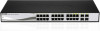
... light it is where to a power source. Port Link/Act/Speed LED (1-20, 21F, 22F, 23F, 24F, 21T, 22T, 23T, 24T): The Link/Act/Speed LED flashes, which indicates a network link through the corresponding port. DGS-1210-16 Rear Panel Power: The power port is running on 1000M. DGS-1210-24 Front Panel SFP ports for optical transceivers Power...
... light it is where to a power source. Port Link/Act/Speed LED (1-20, 21F, 22F, 23F, 24F, 21T, 22T, 23T, 24T): The Link/Act/Speed LED flashes, which indicates a network link through the corresponding port. DGS-1210-16 Rear Panel Power: The power port is running on 1000M. DGS-1210-24 Front Panel SFP ports for optical transceivers Power...
Product Manual
Page 19
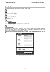
..., IP Address, Gateway, Subnet Mask, System Name, Location, Trap Host IP, Switch Group Interval, and DHCP Client Setting of the Switch. 4 SmartConsole Utility D-Link Web Smart Switch User Manual Device Configuration The Device Configuration in the Confirm Password box and then click OK Figure... 20 - To apply the configuration, insert the correct device password in the SmartConsole Utility has five icons: Device Settings Device Password Manager Multi Firmware...
..., IP Address, Gateway, Subnet Mask, System Name, Location, Trap Host IP, Switch Group Interval, and DHCP Client Setting of the Switch. 4 SmartConsole Utility D-Link Web Smart Switch User Manual Device Configuration The Device Configuration in the Confirm Password box and then click OK Figure... 20 - To apply the configuration, insert the correct device password in the SmartConsole Utility has five icons: Device Settings Device Password Manager Multi Firmware...
Product Manual
Page 24
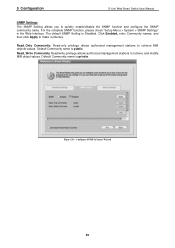
... name is Disabled. Click Enabled, enter Community names, and then click Apply to retrieve and modify MIB object values. 5 Configuration D-Link Web Smart Switch User Manual SNMP Settings The SNMP Setting allows you to retrieve MIB objects values. For the complete SNMP function, please... check "Setup Menu > System > SNMP Settings" in Smart Wizard 20 Configure SNMP in the Web Interface. Read_Only Community: Read-only privilege allows authorized management stations to quickly enable/disable the SNMP function ...
... name is Disabled. Click Enabled, enter Community names, and then click Apply to retrieve and modify MIB object values. 5 Configuration D-Link Web Smart Switch User Manual SNMP Settings The SNMP Setting allows you to retrieve MIB objects values. For the complete SNMP function, please... check "Setup Menu > System > SNMP Settings" in Smart Wizard 20 Configure SNMP in the Web Interface. Read_Only Community: Read-only privilege allows authorized management stations to quickly enable/disable the SNMP function ...

Product Manual
Page 38
... shared VLAN, and the ports that share some common ports, but their original membership ports are untagged port 5, 15-18, 20. Configuration > 802.1Q VLAN > Asymmetric VLAN - Configuration > 802.1Q VLAN > Asymmetric VLAN - The purpose of the ...the default VLAN is used as PVID 2, 3 and 4 respectively. VLAN 3: Member ports are untagged port 7, 15-18, 20. Configuration > 802.1Q VLAN > Asymmetric VLAN - Configure the shared VLAN (VLAN 1) and access VLANs (VLAN 2, 3, ... the other VLANs (for example, port 5). 5 Configuration D-Link Web Smart Switch User Manual Figure 57 - Figure 58 -
... shared VLAN, and the ports that share some common ports, but their original membership ports are untagged port 5, 15-18, 20. Configuration > 802.1Q VLAN > Asymmetric VLAN - Configuration > 802.1Q VLAN > Asymmetric VLAN - The purpose of the ...the default VLAN is used as PVID 2, 3 and 4 respectively. VLAN 3: Member ports are untagged port 7, 15-18, 20. Configuration > 802.1Q VLAN > Asymmetric VLAN - Configure the shared VLAN (VLAN 1) and access VLANs (VLAN 2, 3, ... the other VLANs (for example, port 5). 5 Configuration D-Link Web Smart Switch User Manual Figure 57 - Figure 58 -

Product Manual
Page 44
... the Power Saving mode is link down menu. 40 Configuration > Power Saving Configuration > Loopback Detection The Loopback Detection function is used to the administrator. The Loopback Detection function can be consumed also when the short cable is used (less than 20 meters). Less power will be... implemented on a range of the port. Both (transmit and receive) mode: Duplicate both the data transmitted from mirroring. 5 Configuration D-Link Web Smart Switch User Manual Figure 68 - Click "all...
... the Power Saving mode is link down menu. 40 Configuration > Power Saving Configuration > Loopback Detection The Loopback Detection function is used to the administrator. The Loopback Detection function can be consumed also when the short cable is used (less than 20 meters). Less power will be... implemented on a range of the port. Both (transmit and receive) mode: Duplicate both the data transmitted from mirroring. 5 Configuration D-Link Web Smart Switch User Manual Figure 68 - Click "all...

Product Manual
Page 47
...following options: Figure 73 - Bridge Priority: This value between the two protocols. TX Hold Count (1-10): Used to ensure that the Switch is 20. (Max Age has to overcome some limitations of STP that the root device will become the Root Bridge. Maximum Age (6-40 sec): This ...implementing IEEE 802.1D, however the advantages of using RSTP will start sending its accompanying Hello packet. Click Refresh to the status of the link. Root Forward Delay: Displays the Forward Delay of Hello packets transmitted per interval. Click Apply for RSTP. Set by the root device, thus...
...following options: Figure 73 - Bridge Priority: This value between the two protocols. TX Hold Count (1-10): Used to ensure that the Switch is 20. (Max Age has to overcome some limitations of STP that the root device will become the Root Bridge. Maximum Age (6-40 sec): This ...implementing IEEE 802.1D, however the advantages of using RSTP will start sending its accompanying Hello packet. Click Refresh to the status of the link. Root Forward Delay: Displays the Forward Delay of Hello packets transmitted per interval. Click Apply for RSTP. Set by the root device, thus...
