
User Manual
Page 3
... Web User Interface ...3 Logging onto the Web Manager ...3 Smart Wizard ...4 Web User Interface (Web UI)...8 Areas of Contents 1. DGS-1510 Series Gigabit Ethernet SmartPro Switch Web UI Reference Guide Table of the User Interface...8 3. System...9 Device Information ...9 System Information Settings... ...24 System Log ...25 System Attack Log ...25 Time and SNTP ...26 Clock Settings ...26 Time Zone Settings...26 SNTP Settings ...28 Time Range...29 4. Introduction ...1 Audience ...1 Other Documentation ...1 Conventions ...1 Notes, Notices, and Cautions ...1 2. Management ...31 User Account...
... Web User Interface ...3 Logging onto the Web Manager ...3 Smart Wizard ...4 Web User Interface (Web UI)...8 Areas of Contents 1. DGS-1510 Series Gigabit Ethernet SmartPro Switch Web UI Reference Guide Table of the User Interface...8 3. System...9 Device Information ...9 System Information Settings... ...24 System Log ...25 System Attack Log ...25 Time and SNTP ...26 Clock Settings ...26 Time Zone Settings...26 SNTP Settings ...28 Time Range...29 4. Introduction ...1 Audience ...1 Other Documentation ...1 Conventions ...1 Notes, Notices, and Cautions ...1 2. Management ...31 User Account...

User Manual
Page 36
... summer time will end. Click the Apply button to 99999 seconds. The default value is 60. Select the month that summer time will end. DGS-1510 Series Gigabit Ethernet SmartPro Switch Web UI Reference Guide To: Month To: Time (HH:MM) Offset Select the month that summer time will start.... that summer time will end. Enter the number of minutes to enable or disable SNTP. Select the time of this offset is 720 seconds. 28 The value is used to configure the time settings for Date Setting are described below : Parameter From: Date of the Month From: Month From...
... summer time will end. Click the Apply button to 99999 seconds. The default value is 60. Select the month that summer time will end. DGS-1510 Series Gigabit Ethernet SmartPro Switch Web UI Reference Guide To: Month To: Time (HH:MM) Offset Select the month that summer time will start.... that summer time will end. Enter the number of minutes to enable or disable SNTP. Select the time of this offset is 720 seconds. 28 The value is used to configure the time settings for Date Setting are described below : Parameter From: Date of the Month From: Month From...

User Manual
Page 60
... will appear. 52 Click the Apply button to accept the changes made . Click the Delete button to the previous window. DGS-1510 Series Gigabit Ethernet SmartPro Switch Web UI Reference Guide Figure 4-28 DHCP Relay Pool Source Settings window The fields that can be configured are described below : Parameter Relay Destination Description Enter...
... will appear. 52 Click the Apply button to accept the changes made . Click the Delete button to the previous window. DGS-1510 Series Gigabit Ethernet SmartPro Switch Web UI Reference Guide Figure 4-28 DHCP Relay Pool Source Settings window The fields that can be configured are described below : Parameter Relay Destination Description Enter...

User Manual
Page 111
... states. An example would be created. The Spanning Tree Protocol (STP) operates on a segment is used to use RSTP or MSTP. DGS-1510 Series Gigabit Ethernet SmartPro Switch Web UI Reference Guide Edge Port The edge port is a configurable designation used for migration in full-duplex mode... are designated as shown below: Figure 5-28 STP Global Settings window 103 STP Global Settings This window is updated to view and configure the STP global settings. Ports that legacy ...
... states. An example would be created. The Spanning Tree Protocol (STP) operates on a segment is used to use RSTP or MSTP. DGS-1510 Series Gigabit Ethernet SmartPro Switch Web UI Reference Guide Edge Port The edge port is a configurable designation used for migration in full-duplex mode... are designated as shown below: Figure 5-28 STP Global Settings window 103 STP Global Settings This window is updated to view and configure the STP global settings. Ports that legacy ...

User Manual
Page 209
Time Range Enter the name of the time range to include packet fragment filtering. Figure 8-28 ACL Configuration Wizard (Add Rule for IPv6 ACL) None window The dynamic fields that this rule. Enter the destination IPv6 address and prefix length value ... Length option will appear. When the Host option is selected, enter the source host's IPv6 address here. Select or enter the DSCP value used here. DGS-1510 Series Gigabit Ethernet SmartPro Switch Web UI Reference Guide 1048575.
Time Range Enter the name of the time range to include packet fragment filtering. Figure 8-28 ACL Configuration Wizard (Add Rule for IPv6 ACL) None window The dynamic fields that this rule. Enter the destination IPv6 address and prefix length value ... Length option will appear. When the Host option is selected, enter the source host's IPv6 address here. Select or enter the DSCP value used here. DGS-1510 Series Gigabit Ethernet SmartPro Switch Web UI Reference Guide 1048575.

User Manual
Page 301
...authentication processing time by setting the dead time to accept the changes made. This value must be marked as shown below: Figure 9-28 RADIUS Server Settings window The fields that can be configured are described below : Parameter Dead Time Description Enter the dead time value here... can be between 0 and 65535. If the attempted server does not respond, the system will not be between 1 and 1440 minutes. DGS-1510 Series Gigabit Ethernet SmartPro Switch Web UI Reference Guide Figure 9-27 RADIUS Global Settings window The fields that can be configured are described below ...
...authentication processing time by setting the dead time to accept the changes made. This value must be marked as shown below: Figure 9-28 RADIUS Server Settings window The fields that can be configured are described below : Parameter Dead Time Description Enter the dead time value here... can be between 0 and 65535. If the attempted server does not respond, the system will not be between 1 and 1440 minutes. DGS-1510 Series Gigabit Ethernet SmartPro Switch Web UI Reference Guide Figure 9-27 RADIUS Global Settings window The fields that can be configured are described below ...

User Manual
Page 3
...a Rack ...19 Attaching Brackets to a Switch for the First Time...28 Creating a User Account...29 Configuring the IP Address...30 SNMP Settings...31 Traps...32 Management Information Base (MIB)...32 D-Link Network Assistant (DNA)...33 5. Introduction to Switch Management ...27 Management...into the Transceiver Ports...21 Power On (AC Power) ...21 Power Failure (AC Power) ...22 Installing Power Cord Clip ...22 3. DGS-1510 Series Gigabit Ethernet SmartPro Switch Hardware Installation Guide Table of Contents Table of Contents ...iii Intended Readers ...v Typographical Conventions ...v Notes, Notices...
...a Rack ...19 Attaching Brackets to a Switch for the First Time...28 Creating a User Account...29 Configuring the IP Address...30 SNMP Settings...31 Traps...32 Management Information Base (MIB)...32 D-Link Network Assistant (DNA)...33 5. Introduction to Switch Management ...27 Management...into the Transceiver Ports...21 Power On (AC Power) ...21 Power Failure (AC Power) ...22 Installing Power Cord Clip ...22 3. DGS-1510 Series Gigabit Ethernet SmartPro Switch Hardware Installation Guide Table of Contents Table of Contents ...iii Intended Readers ...v Typographical Conventions ...v Notes, Notices...

User Manual
Page 9
... Reference Guide, Web UI Reference Guide, Hardware Installation Guide, D-View module, D-Link Network Assistant, and D-Link Network Assistant Guide. The carton should contain the following switches are available: DGS-1510-20, DGS-1510-28, DGS-151028P, DGS-1510-28X, DGS-1510-52, and DGS-1510-52X. In the DGS-1510 Series, the following items: • One D-Link DGS-1510 Series Switch. • One Quick Installation Guide. • One AC power...
... Reference Guide, Web UI Reference Guide, Hardware Installation Guide, D-View module, D-Link Network Assistant, and D-Link Network Assistant Guide. The carton should contain the following switches are available: DGS-1510-20, DGS-1510-28, DGS-151028P, DGS-1510-28X, DGS-1510-52, and DGS-1510-52X. In the DGS-1510 Series, the following items: • One D-Link DGS-1510 Series Switch. • One Quick Installation Guide. • One AC power...

User Manual
Page 12
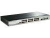
... Ethernet SmartPro Switch Hardware Installation Guide Figure 1-2 Front panel view of a DGS-1510-28 Switch Figure 1-3 Front panel view of a DGS-1510-28P Switch Figure 1-4 Front panel view of a DGS-1510-28X Switch Figure 1-5 Front panel view of a DGS-1510-52 Switch Figure 1-6 Front panel view of a DGS-1510-52X Switch Ports The Type and Number of ports available on the Switch...
... Ethernet SmartPro Switch Hardware Installation Guide Figure 1-2 Front panel view of a DGS-1510-28 Switch Figure 1-3 Front panel view of a DGS-1510-28P Switch Figure 1-4 Front panel view of a DGS-1510-28X Switch Figure 1-5 Front panel view of a DGS-1510-52 Switch Figure 1-6 Front panel view of a DGS-1510-52X Switch Ports The Type and Number of ports available on the Switch...

User Manual
Page 13
...DGS-1510 Series Gigabit Ethernet SmartPro Switch Hardware Installation Guide o Two SFP Ports (1000BASE), o Two Dual Speed SFP+ Ports (1000BASE/10GBASE), o One Console Port (RJ-45), • DGS-1510-28X...: o Twenty-four Copper Ports (10BASE-T/100BASE-TX/1000BASE-T), o Four SFP/SFP+ Ports (1000BASE/10GBASE), o One Console Port (RJ-45), • DGS-1510-52: o Fourty-eight Copper... Two Dual Speed SFP+ Ports (1000BASE/10GBASE), o One Console Port (RJ-45), • DGS-1510-52X: o Fourty-eight Copper Ports (10BASE-T/100BASE-TX/1000BASE-T), o Four SFP/SFP+ Ports (1000BASE...
...DGS-1510 Series Gigabit Ethernet SmartPro Switch Hardware Installation Guide o Two SFP Ports (1000BASE), o Two Dual Speed SFP+ Ports (1000BASE/10GBASE), o One Console Port (RJ-45), • DGS-1510-28X...: o Twenty-four Copper Ports (10BASE-T/100BASE-TX/1000BASE-T), o Four SFP/SFP+ Ports (1000BASE/10GBASE), o One Console Port (RJ-45), • DGS-1510-52: o Fourty-eight Copper... Two Dual Speed SFP+ Ports (1000BASE/10GBASE), o One Console Port (RJ-45), • DGS-1510-52X: o Fourty-eight Copper Ports (10BASE-T/100BASE-TX/1000BASE-T), o Four SFP/SFP+ Ports (1000BASE...

User Manual
Page 16
... Switch Hardware Installation Guide Figure 1-13 Rear panel view of a DGS-1510-20 Switch Figure 1-14 Rear panel view of a DGS-1510-28 Switch Figure 1-15 Rear panel view of a DGS-1510-28P Switch Figure 1-16 Rear panel view of a DGS-1510-28X Switch Figure 1-17 Rear panel view of a DGS-1510-52 Switch Figure 1-18 Rear panel view of the Switch...
... Switch Hardware Installation Guide Figure 1-13 Rear panel view of a DGS-1510-20 Switch Figure 1-14 Rear panel view of a DGS-1510-28 Switch Figure 1-15 Rear panel view of a DGS-1510-28P Switch Figure 1-16 Rear panel view of a DGS-1510-28X Switch Figure 1-17 Rear panel view of a DGS-1510-52 Switch Figure 1-18 Rear panel view of the Switch...

User Manual
Page 18
..., falls below 39°C, the fan will automatically change to the low speed. • DGS-1510-28X: When the internal temperature, detected by the sensor, falls below 43°C, the fan will automatically change to the low speed. • DGS-1510-28: When the internal temperature, detected by the sensor, rises above 45°C, the fan...
..., falls below 39°C, the fan will automatically change to the low speed. • DGS-1510-28X: When the internal temperature, detected by the sensor, falls below 43°C, the fan will automatically change to the low speed. • DGS-1510-28: When the internal temperature, detected by the sensor, rises above 45°C, the fan...

User Manual
Page 28
... no need to turn the Switch off when plugging the console cable into the console port. e. NOTE: Access to the Switch's CLI will be None. DGS-1510 Series Gigabit Ethernet SmartPro Switch Hardware Installation Guide a. b. The Bits per second should be 115200 baud. c. Figure 4-1 Hyperterminal Connection Properties 4. There is on. The Stop... boot-up procedure will be None. The Flow control should be available. Now the Switch can be 8. The Parity should be displayed, as shown below. 28
... no need to turn the Switch off when plugging the console cable into the console port. e. NOTE: Access to the Switch's CLI will be None. DGS-1510 Series Gigabit Ethernet SmartPro Switch Hardware Installation Guide a. b. The Bits per second should be 115200 baud. c. Figure 4-1 Hyperterminal Connection Properties 4. There is on. The Stop... boot-up procedure will be None. The Flow control should be available. Now the Switch can be 8. The Parity should be displayed, as shown below. 28

User Manual
Page 39
.... DGS-1510-52: 2 Fans. DGS-1510-28: 14.6 Watt (100V). 15.2 Watt (240V). DGS-1510-28X: 1 Fan. DGS-1510-28: 1 Fan. Operating: -5°C ~ 50°C (23°F ~ 122°F) Storage: -20°C ~ 70°C (-4°F ~ 158°F) Operating: 0% ~ 95% (non-condensing) Storage: 0% ~ 95% (non-condensing) DGS-1510-20: 280mm (W) 180mm (D) 44mm (H) DGS-1510-28: 440mm (W) 210mm (D) 44mm (H) DGS-1510-28P: 440mm (W) 210mm (D) 44mm (H) 39 DGS-1510-52X: 2 Fans. DGS-1510-28X: 22.3 Watt. DGS-1510...
.... DGS-1510-52: 2 Fans. DGS-1510-28: 14.6 Watt (100V). 15.2 Watt (240V). DGS-1510-28X: 1 Fan. DGS-1510-28: 1 Fan. Operating: -5°C ~ 50°C (23°F ~ 122°F) Storage: -20°C ~ 70°C (-4°F ~ 158°F) Operating: 0% ~ 95% (non-condensing) Storage: 0% ~ 95% (non-condensing) DGS-1510-20: 280mm (W) 180mm (D) 44mm (H) DGS-1510-28: 440mm (W) 210mm (D) 44mm (H) DGS-1510-28P: 440mm (W) 210mm (D) 44mm (H) 39 DGS-1510-52X: 2 Fans. DGS-1510-28X: 22.3 Watt. DGS-1510...

User Manual
Page 40
.... DGS-1510-28: 92 Gbps. DGS-1510 Series Gigabit Ethernet SmartPro Switch Hardware Installation Guide DGS-1510-28X: 440mm (W) 210mm (D) 44mm (H) DGS-1510-52: 440mm (W) 210mm (D) 44mm (H) DGS-1510-52X: 440mm (W) 210mm (D) 44mm (H) Weight DGS-1510-20: 1.235 kg DGS-1510-28: 2.000 kg DGS-1510-28P: 2.536 kg DGS-1510-28X: 2.000 kg DGS-1510-52: 2.400 kg DGS-1510-52X: 2.397 kg MTBF DGS-1510-20: 882152.3682 Hours DGS-1510-28: 516593.2513 Hours DGS-1510-28P: 243090.6950 Hours DGS-1510-28X...
.... DGS-1510-28: 92 Gbps. DGS-1510 Series Gigabit Ethernet SmartPro Switch Hardware Installation Guide DGS-1510-28X: 440mm (W) 210mm (D) 44mm (H) DGS-1510-52: 440mm (W) 210mm (D) 44mm (H) DGS-1510-52X: 440mm (W) 210mm (D) 44mm (H) Weight DGS-1510-20: 1.235 kg DGS-1510-28: 2.000 kg DGS-1510-28P: 2.536 kg DGS-1510-28X: 2.000 kg DGS-1510-52: 2.400 kg DGS-1510-52X: 2.397 kg MTBF DGS-1510-20: 882152.3682 Hours DGS-1510-28: 516593.2513 Hours DGS-1510-28P: 243090.6950 Hours DGS-1510-28X...

User Manual
Page 2
...134 13. DHCP Client Commands...152 17. DHCPv6 Guard Commands ...199 21. DoS Prevention Commands...228 26. Error Recovery Commands...246 28. Filter Database (FDB) Commands...256 30. IP-MAC-Port Binding (IMPB) Commands ...320 37. Loopback Detection (LBD) Commands...385...MLD Snooping Commands ...399 ii DHCPv6 Relay Commands...203 22. D-Link Discovery Protocol (DDP) Client Commands 218 24. IP Source Guard Commands ...310 35. Link Aggregation Control Protocol (LACP) Commands 348 42. DGS-1510 Series Gigabit Ethernet SmartPro Switch CLI Reference Guide Table of Contents...
...134 13. DHCP Client Commands...152 17. DHCPv6 Guard Commands ...199 21. DoS Prevention Commands...228 26. Error Recovery Commands...246 28. Filter Database (FDB) Commands...256 30. IP-MAC-Port Binding (IMPB) Commands ...320 37. Loopback Detection (LBD) Commands...385...MLD Snooping Commands ...399 ii DHCPv6 Relay Commands...203 22. D-Link Discovery Protocol (DDP) Client Commands 218 24. IP Source Guard Commands ...310 35. Link Aggregation Control Protocol (LACP) Commands 348 42. DGS-1510 Series Gigabit Ethernet SmartPro Switch CLI Reference Guide Table of Contents...

User Manual
Page 31
...to initialize a specific port. Default None. Example This example shows how to initialize a specific MAC address. Specifies the number of interfaces. DGS-1510 Series Gigabit Ethernet SmartPro Switch CLI Reference Guide , mac-address MAC-ADDRESS (Optional) Specifies a series of interfaces, or separate a range...form of interfaces from a previous range. The range is 2. Command Default Level Level: 12. Specifies the MAC address to 10. 28 Use the no dot1x max-req Parameters TIMES Default By default, this value is 1 to be initialized. Command Mode Privileged EXEC ...
...to initialize a specific port. Default None. Example This example shows how to initialize a specific MAC address. Specifies the number of interfaces. DGS-1510 Series Gigabit Ethernet SmartPro Switch CLI Reference Guide , mac-address MAC-ADDRESS (Optional) Specifies a series of interfaces, or separate a range...form of interfaces from a previous range. The range is 2. Command Default Level Level: 12. Specifies the MAC address to 10. 28 Use the no dot1x max-req Parameters TIMES Default By default, this value is 1 to be initialized. Command Mode Privileged EXEC ...

User Manual
Page 38
... : 0 Invalid EAPOL Frames RX : 0 EAP-Length Error Frames RX : 0 Last EAPOL Frame Version : 0 Last EAPOL Frame Source : 00-10-28-00-19-78 Switch# 3-15 show dot1x session-statistics [interface INTERFACE-ID [, | -]] Parameters interface INTERFACE-ID , - If not specified, information about ...display 802.1X statistics. If no interface specified, information about all interfaces. Usage Guideline This command can be displayed. DGS-1510 Series Gigabit Ethernet SmartPro Switch CLI Reference Guide Command Mode EXEC Mode or Any Configuration Mode. Using this command without parameters...
... : 0 Invalid EAPOL Frames RX : 0 EAP-Length Error Frames RX : 0 Last EAPOL Frame Version : 0 Last EAPOL Frame Source : 00-10-28-00-19-78 Switch# 3-15 show dot1x session-statistics [interface INTERFACE-ID [, | -]] Parameters interface INTERFACE-ID , - If not specified, information about ...display 802.1X statistics. If no interface specified, information about all interfaces. Usage Guideline This command can be displayed. DGS-1510 Series Gigabit Ethernet SmartPro Switch CLI Reference Guide Command Mode EXEC Mode or Any Configuration Mode. Using this command without parameters...

User Manual
Page 248
... size: 64 Interface VLAN eth1/0/1 100 eth1/0/2 100 eth1/0/3 100 Sender IP Sender MAC Occurrence 10.20.1.1 00-20-30-40-50-60 1 (2014-03-28 23:08:66) 10.5.10.16 55-66-20-30-40-50 2 (2014-04-02 00:11:54) 10.58.2.30 10-22-33-44... EXEC Mode or Any Configuration Mode. The counter of logging entries occurred and the last time of the inspection log buffer. Command Default Level Level: 1. DGS-1510 Series Gigabit Ethernet SmartPro Switch CLI Reference Guide None.
... size: 64 Interface VLAN eth1/0/1 100 eth1/0/2 100 eth1/0/3 100 Sender IP Sender MAC Occurrence 10.20.1.1 00-20-30-40-50-60 1 (2014-03-28 23:08:66) 10.5.10.16 55-66-20-30-40-50 2 (2014-04-02 00:11:54) 10.58.2.30 10-22-33-44... EXEC Mode or Any Configuration Mode. The counter of logging entries occurred and the last time of the inspection log buffer. Command Default Level Level: 1. DGS-1510 Series Gigabit Ethernet SmartPro Switch CLI Reference Guide None.

User Manual
Page 253
...[DIRECTORY-URL] Parameters DIRECTORY-URL Specifies the URL of the local FLASH. Command Mode EXEC Mode. Command Default Level Level: 1. DGS-1510 Series Gigabit Ethernet SmartPro Switch CLI Reference Guide 28. If not specified, the current directory will be shown. Default The default current directory is the root directory on file system ... Guideline If the URL is not specified, then the current directory is used to display the current directory. 250 File System Commands 28-1 cd This command is not changed. Example This example shows how to change the current directory.
...[DIRECTORY-URL] Parameters DIRECTORY-URL Specifies the URL of the local FLASH. Command Mode EXEC Mode. Command Default Level Level: 1. DGS-1510 Series Gigabit Ethernet SmartPro Switch CLI Reference Guide 28. If not specified, the current directory will be shown. Default The default current directory is the root directory on file system ... Guideline If the URL is not specified, then the current directory is used to display the current directory. 250 File System Commands 28-1 cd This command is not changed. Example This example shows how to change the current directory.