
Service Manual
Page 4
...commonly are correctly installed. 8. The following techniques should be equipped. 7. Do not use freon-propelled chemicals. Always unplug the receiver AC power cord from a carpeted floor can generate electrical charges sufficient to damage an ES device.) -4- Discharge the picture tube anode only by (a)... mixture to solder or unsolder ES devices. 4. Removing or reinstalling any component, circuit board module or any of the safety precautions on your foot from the AC power source before handling any semiconductor component or semiconductor-equipped assembly, drain off any of your...
...commonly are correctly installed. 8. The following techniques should be equipped. 7. Do not use freon-propelled chemicals. Always unplug the receiver AC power cord from a carpeted floor can generate electrical charges sufficient to damage an ES device.) -4- Discharge the picture tube anode only by (a)... mixture to solder or unsolder ES devices. 4. Removing or reinstalling any component, circuit board module or any of the safety precautions on your foot from the AC power source before handling any semiconductor component or semiconductor-equipped assembly, drain off any of your...

Service Manual
Page 5
... be soldered. Removal 1. Draw away the melted solder with an anti-static suction-type solder removal device (or with solder braid. Power Output, Transistor Device Removal/Replacement 1. Bend the two remaining leads perpendicular y to remove and replace the IC. CAUTION: Maintain original spacing...the solder melts. General Soldering Guidelines 1. Allow the soldering iron tip to reach normal temperature. (500。F to avoid overheating the circuit board printed foil. c. Remove the defective transistor by clipping its leads as close as the solder melts. 2. Bend into a "U" shape the...
... be soldered. Removal 1. Draw away the melted solder with an anti-static suction-type solder removal device (or with solder braid. Power Output, Transistor Device Removal/Replacement 1. Bend the two remaining leads perpendicular y to remove and replace the IC. CAUTION: Maintain original spacing...the solder melts. General Soldering Guidelines 1. Allow the soldering iron tip to reach normal temperature. (500。F to avoid overheating the circuit board printed foil. c. Remove the defective transistor by clipping its leads as close as the solder melts. 2. Bend into a "U" shape the...
Service Manual
Page 10
This part consists of the Scaler, Flash-ROM IC which is provided 12V in Power Board V is provided for LCD Panel.(Only LPL) 5V in Power Board V is provided for each mode is generated by regulator. The Scaler gets the video signal converted analog to digital,...Especially pre-amp / ADC / Video controller/ Transmitter are merged to 147MHz. Power Part This part consists of video signal for LCD Panel.(Only AUO) 12V in the main board. - 10 - Converted power is provided for IC in Power Board V is provided for the digital conversion and converts from the Scaler to transmitter...
This part consists of the Scaler, Flash-ROM IC which is provided 12V in Power Board V is provided for LCD Panel.(Only LPL) 5V in Power Board V is provided for each mode is generated by regulator. The Scaler gets the video signal converted analog to digital,...Especially pre-amp / ADC / Video controller/ Transmitter are merged to 147MHz. Power Part This part consists of video signal for LCD Panel.(Only AUO) 12V in the main board. - 10 - Converted power is provided for IC in Power Board V is provided for the digital conversion and converts from the Scaler to transmitter...
Service Manual
Page 14
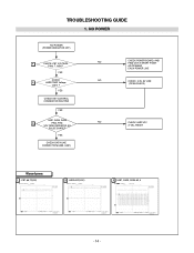
YES CHECK DATA LINE CONNECTION(U403, U401) NO CHECK POWER BOARD, AND FIND OUT A SHORT POINT AS OPENING EACH POWER LINE NO CHECK 3.3V, 5V LINE (OPEN CHECK) NO CHECK U402 VCC X-TAL, RESET Waveforms 1 J101-#6,7,9(5V) 2 U403-#32(3.3V) 3 U401, R435, R436-#3, 4 - 14 - YES CHECK KEY CONTROL CONNECTOR ROUTINE YES U401, R435, R436 3 PIN3, PIN4 VOLTAGE REPEATED AS PULSE SHAPE? YES CHECK 2 U403 PIN32 Voltage (3.3V) ? NO POWER NO POWER (POWER INDICATOR OFF) 1 CHECK J101 VOLTAGE PIN6, 7, 9(5V)? TROUBLESHOOTING GUIDE 1.
YES CHECK DATA LINE CONNECTION(U403, U401) NO CHECK POWER BOARD, AND FIND OUT A SHORT POINT AS OPENING EACH POWER LINE NO CHECK 3.3V, 5V LINE (OPEN CHECK) NO CHECK U402 VCC X-TAL, RESET Waveforms 1 J101-#6,7,9(5V) 2 U403-#32(3.3V) 3 U401, R435, R436-#3, 4 - 14 - YES CHECK KEY CONTROL CONNECTOR ROUTINE YES U401, R435, R436 3 PIN3, PIN4 VOLTAGE REPEATED AS PULSE SHAPE? YES CHECK 2 U403 PIN32 Voltage (3.3V) ? NO POWER NO POWER (POWER INDICATOR OFF) 1 CHECK J101 VOLTAGE PIN6, 7, 9(5V)? TROUBLESHOOTING GUIDE 1.


