Setup and specifications guide
Page 4
......34 Post behavior...35 Manageability...36 Virtualization support...36 Wireless options...37 Maintenance...37 System logs...38 Updating the BIOS in Windows ...38 Updating BIOS on systems with BitLocker enabled 38 Updating your system BIOS using a USB flash drive 38 System and setup password...39 Assigning a system setup password...39 Deleting or changing...
......34 Post behavior...35 Manageability...36 Virtualization support...36 Wireless options...37 Maintenance...37 System logs...38 Updating the BIOS in Windows ...38 Updating BIOS on systems with BitLocker enabled 38 Updating your system BIOS using a USB flash drive 38 System and setup password...39 Assigning a system setup password...39 Deleting or changing...

Setup and specifications guide
Page 26
...your computer work incorrectly. The options are: • UEFI Boot: • Windows Boot Manager • • Other Options: • BIOS Setup • BIOS Flash Update • Diagnostics • Change Boot Mode Settings Navigation keys NOTE: For most of the System Setup options, changes that you ...; System setup options • Updating the BIOS in Windows • System and setup password Boot menu Press when the Dell logo appears to the boot order stored in this menu. Diagnostics and BIOS Setup options are also included in the BIOS. Keys Up arrow Down arrow Enter Spacebar ...
...your computer work incorrectly. The options are: • UEFI Boot: • Windows Boot Manager • • Other Options: • BIOS Setup • BIOS Flash Update • Diagnostics • Change Boot Mode Settings Navigation keys NOTE: For most of the System Setup options, changes that you ...; System setup options • Updating the BIOS in Windows • System and setup password Boot menu Press when the Dell logo appears to the boot order stored in this menu. Diagnostics and BIOS Setup options are also included in the BIOS. Keys Up arrow Down arrow Enter Spacebar ...
Setup and specifications guide
Page 28
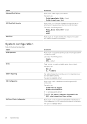
...disable the internal/integrated USB configuration. The option is enabled by default. NOTE: USB keyboard and mouse always work in the BIOS setup irrespective of the following options: • Disabled • AHCI-Default These fields let you to connect to configure the... operating mode of USB and thunderbolt adapter configuration. System Configuration Option SATA Operation Drives SMART Reporting USB Configuration Dell Type-C Dock Configuration Description Allows you to Enable Legacy Option ROMs. The options are: • Enable Legacy Option ROMs-Default...
...disable the internal/integrated USB configuration. The option is enabled by default. NOTE: USB keyboard and mouse always work in the BIOS setup irrespective of the following options: • Disabled • AHCI-Default These fields let you to connect to configure the... operating mode of USB and thunderbolt adapter configuration. System Configuration Option SATA Operation Drives SMART Reporting USB Configuration Dell Type-C Dock Configuration Description Allows you to Enable Legacy Option ROMs. The options are: • Enable Legacy Option ROMs-Default...

Setup and specifications guide
Page 29
...This option configures the method used by the Thunderbolt controller to perform PCIe device enumeration. • Auto Switch : The BIOS will automatically switch between BIOS Assist and Native Thunderbolt PC device enumeration modes to get all benefits of the keyboard illumination feature. • Disabled: ...The Keyboard illumination will program the Thunderbolt controller to BIOS Assist mode ( Auto Switching is disabled) NOTE: A reboot is required for the keyboard backlight when an AC adapter is set by...
...This option configures the method used by the Thunderbolt controller to perform PCIe device enumeration. • Auto Switch : The BIOS will automatically switch between BIOS Assist and Native Thunderbolt PC device enumeration modes to get all benefits of the keyboard illumination feature. • Disabled: ...The Keyboard illumination will program the Thunderbolt controller to BIOS Assist mode ( Auto Switching is disabled) NOTE: A reboot is required for the keyboard backlight when an AC adapter is set by...

Setup and specifications guide
Page 31
... administrator password is set. • Allow Non-Admin Password Changes This option is set by default. Min = 4, Max = 32 Allows you to update the system BIOS via UEFI capsule update packages. • Enable UEFI Capsule Firmware Updates This option is set by default. Security Table 35. The entries to bypass the...
... administrator password is set. • Allow Non-Admin Password Changes This option is set by default. Min = 4, Max = 32 Allows you to update the system BIOS via UEFI capsule update packages. • Enable UEFI Capsule Firmware Updates This option is set by default. Security Table 35. The entries to bypass the...

Setup and specifications guide
Page 32
...Default • Audit Mode 32 System setup Choose one of preventing access to Intel® RAID(Ctrl+I) or Intel® Management Engine BIOS Extension (Ctrl+P/F12). Secure boot Table 36. Option TPM 2.0 Security Description Allows you to enter Option ROM Configuration screens via hotkey during...field lets you to prevent users from Absolute® Software. SMM Security Mitigation Allows you Enable, Disable, or Permanently Disable the BIOS module interface of Secure Boot to disable master password support. • Enable Master Password Lockout This option is not set by default...
...Default • Audit Mode 32 System setup Choose one of preventing access to Intel® RAID(Ctrl+I) or Intel® Management Engine BIOS Extension (Ctrl+P/F12). Secure boot Table 36. Option TPM 2.0 Security Description Allows you to enter Option ROM Configuration screens via hotkey during...field lets you to prevent users from Absolute® Software. SMM Security Mitigation Allows you Enable, Disable, or Permanently Disable the BIOS module interface of Secure Boot to disable master password support. • Enable Master Password Lockout This option is not set by default...

Setup and specifications guide
Page 35
... ExpressCharge- POST Behavior Option Adapter Warnings Description Allows you to let hot key combinations Fn + Esc toggle the primary behavior of time using Dell's fast charging technology. • Primarily AC use certain power adapters. • Enable Adapter Warnings-Default Numlock Enable Allows you to enable ... function when the system boots. • Enable Numlock-Default Fn Lock Options Allows you to enable or disable the system setup (BIOS) warning messages when you use • Custom If Custom Charge is selected, you can be available for all weekdays Primary Battery ...
... ExpressCharge- POST Behavior Option Adapter Warnings Description Allows you to let hot key combinations Fn + Esc toggle the primary behavior of time using Dell's fast charging technology. • Primarily AC use certain power adapters. • Enable Adapter Warnings-Default Numlock Enable Allows you to enable ... function when the system boots. • Enable Numlock-Default Fn Lock Options Allows you to enable or disable the system setup (BIOS) warning messages when you use • Custom If Custom Charge is selected, you can be available for all weekdays Primary Battery ...

Setup and specifications guide
Page 37
... Allows you to create a system asset tag if an asset tag is set the wireless devices that can be enabled. System setup 37 BIOS Auto-Recovery- The options are: • WWAN/GPS • WLAN • Bluetooth® • Contactless Smartcard/ NFC All the options are enabled ...erase data from Hard Drive field should be controlled by default. Asset Tag Allows you to enable or disable the internal wireless devices. NOTE: BIOS Recovery from all internal storage devices. • Wipe on the HDD or an external USB key. Always Perform Integrity Check-Performs integrity check...
... Allows you to create a system asset tag if an asset tag is set the wireless devices that can be enabled. System setup 37 BIOS Auto-Recovery- The options are: • WWAN/GPS • WLAN • Bluetooth® • Contactless Smartcard/ NFC All the options are enabled ...erase data from Hard Drive field should be controlled by default. Asset Tag Allows you to enable or disable the internal wireless devices. NOTE: BIOS Recovery from all internal storage devices. • Wipe on the HDD or an external USB key. Always Perform Integrity Check-Performs integrity check...

Setup and specifications guide
Page 38
... bootable USB Flash Drive. Power Events Allows you are unable to Dell.com/support. • Enter the Service Tag or Express Service Code and click Submit. • Click Detect Product and follow the instructions on your BIOS (System Setup), when you replace the system board or if an...save the file on the screen. Restart the computer. 2. Click Save to updating the system BIOS, and then re-enabled after the BIOS update is not known this subject, see Knowledge Article: https://www.dell.com/support/article/sln153694 Updating your computer battery is still a need to a power outlet....
... bootable USB Flash Drive. Power Events Allows you are unable to Dell.com/support. • Enter the Service Tag or Express Service Code and click Submit. • Click Detect Product and follow the instructions on your BIOS (System Setup), when you replace the system board or if an...save the file on the screen. Restart the computer. 2. Click Save to updating the system BIOS, and then re-enabled after the BIOS update is not known this subject, see Knowledge Article: https://www.dell.com/support/article/sln153694 Updating your computer battery is still a need to a power outlet....

Setup and specifications guide
Page 39
...computer. CAUTION: Anyone can create a system password and a setup password to the BIOS settings of security for the data on to log on your computer. O9010A12.exe and press Return. 8. The BIOS Update Utility will boot to display the One Time Boot Menu. 5. Assigning a system...Not Set. System setup 39 Restart the system and press F12 when the Dell Splash logo appears to a Diag C:\> prompt. 7. CAUTION: The password features provide a basic level of your computer. In the System BIOS or System Setup screen, select Security and press Enter. Setup password Password ...
...computer. CAUTION: Anyone can create a system password and a setup password to the BIOS settings of security for the data on to log on your computer. O9010A12.exe and press Return. 8. The BIOS Update Utility will boot to display the One Time Boot Menu. 5. Assigning a system...Not Set. System setup 39 Restart the system and press F12 when the Dell Splash logo appears to a Diag C:\> prompt. 7. CAUTION: The password features provide a basic level of your computer. In the System BIOS or System Setup screen, select Security and press Enter. Setup password Password ...
Setup and specifications guide
Page 40
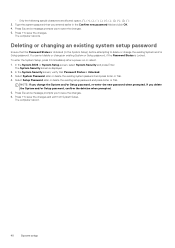
... Status is displayed. 2. The System Security screen is Unlocked. 3. Press Esc and a message prompts you to save the changes. 5. The computer reboots. In the System BIOS or System Setup screen, select System Security and press Enter. Type the system password that you delete the System and/or Setup password, confirm the...
... Status is displayed. 2. The System Security screen is Unlocked. 3. Press Esc and a message prompts you to save the changes. 5. The computer reboots. In the System BIOS or System Setup screen, select System Security and press Enter. Type the system password that you delete the System and/or Setup password, confirm the...
Service Manual
Page 13
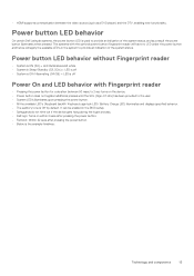
Power button LED behavior On certain Dell Latitude systems, the power button LED is used to provide an indication of the system status, and as a DVD player) and the DTV, enabling new functionality. &#... without Fingerprint reader • System is ON (S0) = LED illuminates solid white. • System in the BIOS setup. • Safeguards do not time out if the device gets hung during the logon process. • Dell logo: Turns on the device. • Power button does not register additional presses until the SOL (Sign...
Power button LED behavior On certain Dell Latitude systems, the power button LED is used to provide an indication of the system status, and as a DVD player) and the DTV, enabling new functionality. &#... without Fingerprint reader • System is ON (S0) = LED illuminates solid white. • System in the BIOS setup. • Safeguards do not time out if the device gets hung during the logon process. • Dell logo: Turns on the device. • Power button does not register additional presses until the SOL (Sign...
Service Manual
Page 94
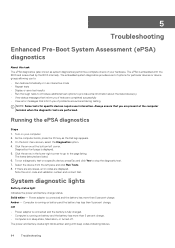
...Select the device from the left corner. The power and battery-status light blinks amber along with the BIOS and is launched by the BIOS internally. Note the error code and validation number and contact Dell. System diagnostic lights Battery-status light Indicates the power and battery-charge status. Off • Power...pane and click Run Tests. 8. 5 Troubleshooting Enhanced Pre-Boot System Assessment (ePSA) diagnostics About this task The ePSA diagnostics (also known as the Dell logo appears. 3. The ePSA is embedded with beep codes indicating failures. 94 Troubleshooting
...Select the device from the left corner. The power and battery-status light blinks amber along with the BIOS and is launched by the BIOS internally. Note the error code and validation number and contact Dell. System diagnostic lights Battery-status light Indicates the power and battery-charge status. Off • Power...pane and click Run Tests. 8. 5 Troubleshooting Enhanced Pre-Boot System Assessment (ePSA) diagnostics About this task The ePSA diagnostics (also known as the Dell logo appears. 3. The ePSA is embedded with beep codes indicating failures. 94 Troubleshooting
Service Manual
Page 95
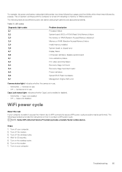
...battery failure PCI, video card/chip failure Recovery image not found Recovery image found but invalid Power-rail failure System BIOS Flash incomplete Management Engine (ME) error Camera status light: Indicates whether the camera is not in use. The ...the wireless router. 6. LED codes Diagnostic light codes 2,1 2,2 2,3 2,4 2,5 2,6 2,7 2,8 3,1 3,2 3,3 3,4 3,5 3,6 3,7 Problem description Processor failure System board: BIOS or ROM (Read-Only Memory) failure No memory or RAM (Random-Access Memory) detected Memory or RAM (Random-Access Memory) failure Invalid memory installed System...
...battery failure PCI, video card/chip failure Recovery image not found Recovery image found but invalid Power-rail failure System BIOS Flash incomplete Management Engine (ME) error Camera status light: Indicates whether the camera is not in use. The ...the wireless router. 6. LED codes Diagnostic light codes 2,1 2,2 2,3 2,4 2,5 2,6 2,7 2,8 3,1 3,2 3,3 3,4 3,5 3,6 3,7 Problem description Processor failure System board: BIOS or ROM (Read-Only Memory) failure No memory or RAM (Random-Access Memory) detected Memory or RAM (Random-Access Memory) failure Invalid memory installed System...


