
Latitude 5350/Latitude 5350 2-in-1 Owners Manual
Page 3
... Chapter 1: Views of Latitude 5350/Latitude 5350 2-in-1 7 Right...7 Left...8 Top...9 Front view of Latitude 5350 laptop...10 Front view of Latitude 5350 2-in-1...11 Bottom...12 Service Tag...12 Modes...13 Battery charge and status light ...15 Chapter 2: Set up your Latitude 5350/Latitude 5350 2-in-1 16 Chapter 3: Specifications of Latitude 5350/Latitude 5350 2-in-1 18 Dimensions and...reader...33 Contactless smart-card reader...33 Contacted smart-card reader...36 Operating and storage environment...37 Dell support policy...38 ComfortView Plus...38 Using the privacy shutter...38 Contents 3
... Chapter 1: Views of Latitude 5350/Latitude 5350 2-in-1 7 Right...7 Left...8 Top...9 Front view of Latitude 5350 laptop...10 Front view of Latitude 5350 2-in-1...11 Bottom...12 Service Tag...12 Modes...13 Battery charge and status light ...15 Chapter 2: Set up your Latitude 5350/Latitude 5350 2-in-1 16 Chapter 3: Specifications of Latitude 5350/Latitude 5350 2-in-1 18 Dimensions and...reader...33 Contactless smart-card reader...33 Contacted smart-card reader...36 Operating and storage environment...37 Dell support policy...38 ComfortView Plus...38 Using the privacy shutter...38 Contents 3
Latitude 5350/Latitude 5350 2-in-1 Owners Manual
Page 10
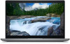
Camera shutter Slide the privacy shutter to the left to video chat, capture photos, and record videos. 3. Left microphone Provides digital sound input for audio recording and voice calls. 10 Views of Latitude 5350/Latitude 5350 2-in use. 5. Camera-status light Turns on when the camera is in -1 Front view of Latitude 5350 laptop Figure 4. Camera Enables you to access the camera lens. 4. Right microphone Provides digital sound input for audio recording and voice calls. 2. Front view of Latitude 5350 laptop 1.
Camera shutter Slide the privacy shutter to the left to video chat, capture photos, and record videos. 3. Left microphone Provides digital sound input for audio recording and voice calls. 10 Views of Latitude 5350/Latitude 5350 2-in use. 5. Camera-status light Turns on when the camera is in -1 Front view of Latitude 5350 laptop Figure 4. Camera Enables you to access the camera lens. 4. Right microphone Provides digital sound input for audio recording and voice calls. 2. Front view of Latitude 5350 laptop 1.
Latitude 5350/Latitude 5350 2-in-1 Owners Manual
Page 16
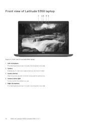
Figure 12. NOTE: Ubuntu is supported only on Latitude 5350 laptop and not on for the first time. 2. When setting up, Dell Technologies recommends that the power adapter is turned on 2-in-1 configuration. Locate and use Dell apps from your computer depending on the configuration you : ● ... For more information about installing and configuring Ubuntu, search in the Knowledge Base Resource at www.dell.com/support. Finish the operating system setup. 2 Set up your Latitude 5350/Latitude 5350 2in-1 About this task NOTE: The images in this document may go into power-saving mode ...
Figure 12. NOTE: Ubuntu is supported only on Latitude 5350 laptop and not on for the first time. 2. When setting up, Dell Technologies recommends that the power adapter is turned on 2-in-1 configuration. Locate and use Dell apps from your computer depending on the configuration you : ● ... For more information about installing and configuring Ubuntu, search in the Knowledge Base Resource at www.dell.com/support. Finish the operating system setup. 2 Set up your Latitude 5350/Latitude 5350 2in-1 About this task NOTE: The images in this document may go into power-saving mode ...
Latitude 5350/Latitude 5350 2-in-1 Owners Manual
Page 18
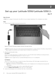
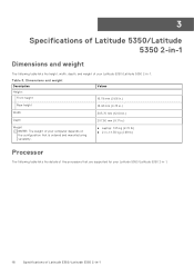
... depends on the configuration that are supported for your Latitude 5350/Latitude 5350 2-in -1 Table 3. 3 Specifications of Latitude 5350/Latitude 5350 2-in-1 Dimensions and weight The following table lists the height, width, depth, and weight of your Latitude 5350/Latitude 5350 2-in-1. 18 Specifications of the processors that is ordered and manufacturing variability. ● Laptop: 1.23 kg (2.72 lb) ● 2-in-1: 1.35 kg...
... depends on the configuration that are supported for your Latitude 5350/Latitude 5350 2-in -1 Table 3. 3 Specifications of Latitude 5350/Latitude 5350 2-in-1 Dimensions and weight The following table lists the height, width, depth, and weight of your Latitude 5350/Latitude 5350 2-in-1. 18 Specifications of the processors that is ordered and manufacturing variability. ● Laptop: 1.23 kg (2.72 lb) ● 2-in-1: 1.35 kg...
Latitude 5350/Latitude 5350 2-in-1 Owners Manual
Page 21
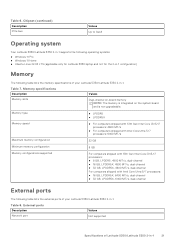
...9679; Windows 11 Home ● Ubuntu Linux 22.04 LTS (applicable only for Latitude 5350 laptop and not for the 2-in-1 configuration) Memory The following table lists the external ports of your Latitude 5350/Latitude 5350 2-in -1. Memory type ● LPDDR5 ● LPDDR5X Memory speed ●... dual-channel ● 32 GB, LPDDR5X, 6400 MT/s, dual-channel External ports The following table lists the memory specifications of Latitude 5350/Latitude 5350 2-in-1 21 Table 8. Table 7. Table 6. Memory specifications Description Memory slots Values Dual-channel on-board memory NOTE: The...
...9679; Windows 11 Home ● Ubuntu Linux 22.04 LTS (applicable only for Latitude 5350 laptop and not for the 2-in-1 configuration) Memory The following table lists the external ports of your Latitude 5350/Latitude 5350 2-in -1. Memory type ● LPDDR5 ● LPDDR5X Memory speed ●... dual-channel ● 32 GB, LPDDR5X, 6400 MT/s, dual-channel External ports The following table lists the memory specifications of Latitude 5350/Latitude 5350 2-in-1 21 Table 8. Table 7. Table 6. Memory specifications Description Memory slots Values Dual-channel on-board memory NOTE: The...
Latitude 5350/Latitude 5350 2-in-1 Owners Manual
Page 32
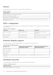
... Latitude 5350/Latitude 5350 2-in-1. Table 25. Hardware security The following table lists the hardware security of your Latitude 5350/Latitude 5350 2-in-1. External display support Graphics card Supported external displays with laptop display enabled Supported external displays with Proximity/ALS/IR camera and 100% attached on www.dell.com/ support. Sensor The following table lists the sensor of your Latitude 5350/ Latitude 5350...
... Latitude 5350/Latitude 5350 2-in-1. Table 25. Hardware security The following table lists the hardware security of your Latitude 5350/Latitude 5350 2-in-1. External display support Graphics card Supported external displays with laptop display enabled Supported external displays with Proximity/ALS/IR camera and 100% attached on www.dell.com/ support. Sensor The following table lists the sensor of your Latitude 5350/ Latitude 5350...
Latitude 5350/Latitude 5350 2-in-1 Owners Manual
Page 96
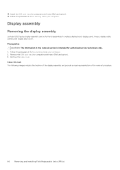
... intended for computers with nano-SIM card option). 14. Remove the SIM card tray (for authorized service technicians only. 1. Display assembly Removing the display assembly Latitude 5350 laptop display assembly can be further disassembled to replace display bezel, display panel, hinges, display cable, camera, and display back cover.
... intended for computers with nano-SIM card option). 14. Remove the SIM card tray (for authorized service technicians only. 1. Display assembly Removing the display assembly Latitude 5350 laptop display assembly can be further disassembled to replace display bezel, display panel, hinges, display cable, camera, and display back cover.
Latitude 5350/Latitude 5350 2-in-1 Owners Manual
Page 101
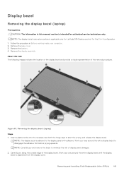
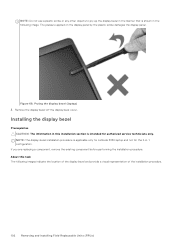
... 1. Remove the display assembly. Work your way around the entire display bezel until the display bezel is applicable only for Latitude 5350 laptop and not for authorized service technicians only. Work your computer. 2. Removing and installing Field Replaceable Units (FRUs) 101 Carefully ... pry and remove the bezel to start the prying, and release the display bezel. Figure 67. Display bezel Removing the display bezel (laptop) Prerequisites CAUTION: The information in this task The following images indicate the location of the display bezel and provide a visual representation of ...
... 1. Remove the display assembly. Work your way around the entire display bezel until the display bezel is applicable only for Latitude 5350 laptop and not for authorized service technicians only. Work your computer. 2. Removing and installing Field Replaceable Units (FRUs) 101 Carefully ... pry and remove the bezel to start the prying, and release the display bezel. Figure 67. Display bezel Removing the display bezel (laptop) Prerequisites CAUTION: The information in this task The following images indicate the location of the display bezel and provide a visual representation of ...
Latitude 5350/Latitude 5350 2-in-1 Owners Manual
Page 102
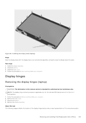
... cover. Figure 68. If you are replacing a component, remove the existing component before performing the installation procedure. About this installation section is applicable only for Latitude 5350 laptop and not for authorized service technicians only. NOTE: The display-bezel installation procedure is intended for the 2-in the following images indicate the location of...
... cover. Figure 68. If you are replacing a component, remove the existing component before performing the installation procedure. About this installation section is applicable only for Latitude 5350 laptop and not for authorized service technicians only. NOTE: The display-bezel installation procedure is intended for the 2-in the following images indicate the location of...
Latitude 5350/Latitude 5350 2-in-1 Owners Manual
Page 103
... CAUTION: The information in -1 configuration. 1. About this removal section is applicable only for the Latitude 5350 laptop and not for authorized service technicians only. Install the display assembly. 2. Follow the procedure in Before working inside your computer. Remove ...the location of the display hinges and provide a visual representation of the removal procedure. Install the base cover. 4. Installing the display bezel (laptop) Steps Align the display bezel with the display back cover and antenna assembly, and gently snap the display bezel into place. Install the battery....
... CAUTION: The information in -1 configuration. 1. About this removal section is applicable only for the Latitude 5350 laptop and not for authorized service technicians only. Install the display assembly. 2. Follow the procedure in Before working inside your computer. Remove ...the location of the display hinges and provide a visual representation of the removal procedure. Install the base cover. 4. Installing the display bezel (laptop) Steps Align the display bezel with the display back cover and antenna assembly, and gently snap the display bezel into place. Install the battery....
Latitude 5350/Latitude 5350 2-in-1 Owners Manual
Page 104
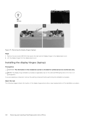
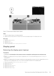
Removing the display hinges (laptop) Steps 1. If you are replacing a component, remove the existing component before performing the installation procedure. Remove the six screws (M2.5x3) that secure the ...the display back cover. 2. Lift the display hinges from the display back cover. Installing the display hinges (laptop) Prerequisites CAUTION: The information in -1 configuration. About this installation section is applicable only for the Latitude 5350 laptop and not for authorized service technicians only. NOTE: The display-hinge installation procedure is intended for the 2-...
Removing the display hinges (laptop) Steps 1. If you are replacing a component, remove the existing component before performing the installation procedure. Remove the six screws (M2.5x3) that secure the ...the display back cover. 2. Lift the display hinges from the display back cover. Installing the display hinges (laptop) Prerequisites CAUTION: The information in -1 configuration. About this installation section is applicable only for the Latitude 5350 laptop and not for authorized service technicians only. NOTE: The display-hinge installation procedure is intended for the 2-...
Latitude 5350/Latitude 5350 2-in-1 Owners Manual
Page 105
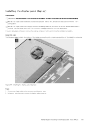
... assembly. 2. Remove the battery. 4. Install the battery. 3. NOTE: The display-panel removal procedure is applicable only for the Latitude 5350 laptop and not for authorized service technicians only. NOTE: The display panel and its support brackets are a single assembly and cannot be ... configuration. Follow the procedure in this removal section is removed from the display panel. 1. Display panel Removing the display panel (laptop) Prerequisites CAUTION: The information in After working inside your computer. 2. Do not remove the support brackets from the display back cover...
... assembly. 2. Remove the battery. 4. Install the battery. 3. NOTE: The display-panel removal procedure is applicable only for the Latitude 5350 laptop and not for authorized service technicians only. NOTE: The display panel and its support brackets are a single assembly and cannot be ... configuration. Follow the procedure in this removal section is removed from the display panel. 1. Display panel Removing the display panel (laptop) Prerequisites CAUTION: The information in After working inside your computer. 2. Do not remove the support brackets from the display back cover...
Latitude 5350/Latitude 5350 2-in-1 Owners Manual
Page 109
Installing the display panel (laptop) Steps 1. NOTE: The display panel and its support brackets are replacing a component, remove the existing component before performing the installation procedure. If you are a single ... images indicate the location of the display panel and provide a visual representation of the installation procedure. About this installation section is applicable only for the Latitude 5350 laptop and not for authorized service technicians only. Figure 77. Do not remove the support brackets from the display back cover. Installing the display panel...
Installing the display panel (laptop) Steps 1. NOTE: The display panel and its support brackets are replacing a component, remove the existing component before performing the installation procedure. If you are a single ... images indicate the location of the display panel and provide a visual representation of the installation procedure. About this installation section is applicable only for the Latitude 5350 laptop and not for authorized service technicians only. Figure 77. Do not remove the support brackets from the display back cover. Installing the display panel...
Latitude 5350/Latitude 5350 2-in-1 Owners Manual
Page 112
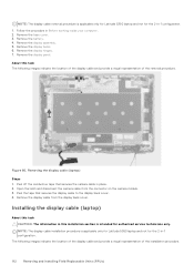
... the display back cover. 4. Remove the base cover. 3. About this installation section is applicable only for Latitude 5350 laptop and not for the 2-in place. 2. Remove the display assembly. 5. Removing the display cable (laptop) Steps 1. Follow the procedure in -1 configuration. 1. Open the latch and disconnect the camera cable from... is intended for the 2-in Before working inside your computer. 2. NOTE: The display cable removal procedure is applicable only for Latitude 5350 laptop and not for authorized service technicians only. Remove the display bezel. 6.
... the display back cover. 4. Remove the base cover. 3. About this installation section is applicable only for Latitude 5350 laptop and not for the 2-in place. 2. Remove the display assembly. 5. Removing the display cable (laptop) Steps 1. Follow the procedure in -1 configuration. 1. Open the latch and disconnect the camera cable from... is intended for the 2-in Before working inside your computer. 2. NOTE: The display cable removal procedure is applicable only for Latitude 5350 laptop and not for authorized service technicians only. Remove the display bezel. 6.
Latitude 5350/Latitude 5350 2-in-1 Owners Manual
Page 113
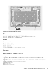
...the camera cable in place. 2. Install the base cover. 7. Follow the procedure in this removal section is applicable only for Latitude 5350 laptop and not for authorized service technicians only. Remove the base cover. 3. Removing and installing Field Replaceable Units (FRUs) 113 Install...the display panel. 2. Install the battery. 6. Camera Removing the camera (laptop) Prerequisites CAUTION: The information in Before working inside your computer. Remove the display assembly. Installing the display cable (laptop) Steps 1. Connect the camera cable from the connector on the camera ...
...the camera cable in place. 2. Install the base cover. 7. Follow the procedure in this removal section is applicable only for Latitude 5350 laptop and not for authorized service technicians only. Remove the base cover. 3. Removing and installing Field Replaceable Units (FRUs) 113 Install...the display panel. 2. Install the battery. 6. Camera Removing the camera (laptop) Prerequisites CAUTION: The information in Before working inside your computer. Remove the display assembly. Installing the display cable (laptop) Steps 1. Connect the camera cable from the connector on the camera ...
Latitude 5350/Latitude 5350 2-in-1 Owners Manual
Page 115
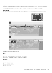
... connector on the display back cover. 2. Install the display assembly. 5. NOTE: The camera installation procedure is applicable only for Latitude 5350 laptop and not for the 2-in-1 configuration. Install the display bezel. 4. Installing the camera (laptop) Steps 1. Install the display panel. 2. Insert the camera into the slot on the camera. Install the battery. Figure...
... connector on the display back cover. 2. Install the display assembly. 5. NOTE: The camera installation procedure is applicable only for Latitude 5350 laptop and not for the 2-in-1 configuration. Install the display bezel. 4. Installing the camera (laptop) Steps 1. Install the display panel. 2. Insert the camera into the slot on the camera. Install the battery. Figure...
Latitude 5350/Latitude 5350 2-in-1 Owners Manual
Page 116
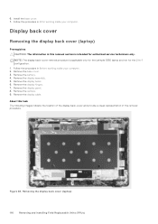
... the procedure in Before working inside your computer. Remove the display bezel. 6. Remove the display cable. About this removal section is applicable only for the Latitude 5350 laptop and not for authorized service technicians only. Install the base cover. 7. 6. Remove the display assembly. 5. Remove the display hinges. 7. Removing the display back cover...
... the procedure in Before working inside your computer. Remove the display bezel. 6. Remove the display cable. About this removal section is applicable only for the Latitude 5350 laptop and not for authorized service technicians only. Install the base cover. 7. 6. Remove the display assembly. 5. Remove the display hinges. 7. Removing the display back cover...
Latitude 5350/Latitude 5350 2-in-1 Owners Manual
Page 117
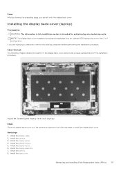
...camera. 3. Steps After performing the preceding steps, you are left with the display back cover. About this installation section is applicable only for Latitude 5350 laptop and not for authorized service technicians only. Install the display cable. 2. Install the display panel. 4. Install the display assembly. 7. Install.... 8. NOTE: The display back-cover installation procedure is intended for the 2-in-1 configuration. Installing the display back-cover (laptop) Prerequisites CAUTION: The information in this task The following steps to install the display back cover.
...camera. 3. Steps After performing the preceding steps, you are left with the display back cover. About this installation section is applicable only for Latitude 5350 laptop and not for authorized service technicians only. Install the display cable. 2. Install the display panel. 4. Install the display assembly. 7. Install.... 8. NOTE: The display back-cover installation procedure is intended for the 2-in-1 configuration. Installing the display back-cover (laptop) Prerequisites CAUTION: The information in this task The following steps to install the display back cover.
Latitude 5350/Latitude 5350 2-in-1 Owners Manual
Page 118
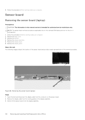
...on the sensor board. 2. Follow the procedure in -1 configuration. 1. About this removal section is applicable only for the Latitude 5340 laptop and not for authorized service technicians only. Remove the display panel. Open the latch and disconnect the display cable from ... representation of the removal procedure. Sensor board Removing the sensor board (laptop) Prerequisites CAUTION: The information in After working inside your computer. 2. Remove the display assembly. 5. Removing the sensor board (laptop) Steps 1. Remove the display cable from the display assembly. 118 ...
...on the sensor board. 2. Follow the procedure in -1 configuration. 1. About this removal section is applicable only for the Latitude 5340 laptop and not for authorized service technicians only. Remove the display panel. Open the latch and disconnect the display cable from ... representation of the removal procedure. Sensor board Removing the sensor board (laptop) Prerequisites CAUTION: The information in After working inside your computer. 2. Remove the display assembly. 5. Removing the sensor board (laptop) Steps 1. Remove the display cable from the display assembly. 118 ...
Latitude 5350/Latitude 5350 2-in-1 Owners Manual
Page 119
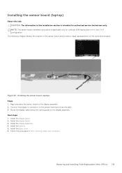
... this task CAUTION: The information in this installation section is applicable only for Latitude 5340 laptop and not for authorized service technicians only. Figure 87. Install the display assembly. 4. Follow the procedure in -1 configuration. Removing and installing Field Replaceable Units (FRUs) ... After working inside your computer. Install the battery. 5. Install the base cover. 6. Connect the display to connector on the display assembly. Installing the sensor board (laptop) Steps 1. Next steps 1. Align and place the sensor board on the display assembly. 2.
... this task CAUTION: The information in this installation section is applicable only for Latitude 5340 laptop and not for authorized service technicians only. Figure 87. Install the display assembly. 4. Follow the procedure in -1 configuration. Removing and installing Field Replaceable Units (FRUs) ... After working inside your computer. Install the battery. 5. Install the base cover. 6. Connect the display to connector on the display assembly. Installing the sensor board (laptop) Steps 1. Next steps 1. Align and place the sensor board on the display assembly. 2.


