
Handling swollen Lithium-ion batteries
Page 1
... to work with newer ultra-thin laptops) and long battery life. Swollen batteries should not be used and should be returned to Dell in the electronics industry due to lithium-ion polymer battery technology is the lithium-ion polymer battery. Replace the battery only with a compatible battery purchased from Dell that is fully discharged. ● Do not crush, drop...
... to work with newer ultra-thin laptops) and long battery life. Swollen batteries should not be used and should be returned to Dell in the electronics industry due to lithium-ion polymer battery technology is the lithium-ion polymer battery. Replace the battery only with a compatible battery purchased from Dell that is fully discharged. ● Do not crush, drop...
Owners Manual
Page 5
... all insulator parts while performing service and that they use only the battery designed for few seconds, to place these parts in anti-static bags for other Dell computers. 1 Connect any external devices, such as a port replicator or media base, and replace any cards, such as touching a connector on your computer 5 CAUTION: To...
... all insulator parts while performing service and that they use only the battery designed for few seconds, to place these parts in anti-static bags for other Dell computers. 1 Connect any external devices, such as a port replicator or media base, and replace any cards, such as touching a connector on your computer 5 CAUTION: To...

Owners Manual
Page 11
... https://www.dell.com/support for assistance and further instructions. • Always purchase genuine batteries from the system [3]. NOTE: The Latitude 7290 features either a 3-cell or 4-cell battery, which needs to be replaced. Battery Lithium-ion battery precautions CAUTION: • Exercise caution when handling Lithium-ion batteries. • Discharge the battery as much as possible before replacing the customer replaceable unit (CRU...
... https://www.dell.com/support for assistance and further instructions. • Always purchase genuine batteries from the system [3]. NOTE: The Latitude 7290 features either a 3-cell or 4-cell battery, which needs to be replaced. Battery Lithium-ion battery precautions CAUTION: • Exercise caution when handling Lithium-ion batteries. • Discharge the battery as much as possible before replacing the customer replaceable unit (CRU...
Owners Manual
Page 15
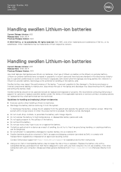
Installing speaker module 1 Place the speaker module into the slots on the system. 2 Replace the four (M2.0 x 3.0) screws to secure the speaker to the connector on the system. NOTE: Speaker cables are routed below the securing latch on the ... buttons bracket using tape. 4 Connect the speaker cable to the system. 3 Route the speaker cable through the retention clips on the system board. 5 Install the: a battery b base cover 6 Follow the procedure in Before working inside your computer. b Lift the speaker module from the computer [2]. Coin cell...
Installing speaker module 1 Place the speaker module into the slots on the system. 2 Replace the four (M2.0 x 3.0) screws to secure the speaker to the connector on the system. NOTE: Speaker cables are routed below the securing latch on the ... buttons bracket using tape. 4 Connect the speaker cable to the system. 3 Route the speaker cable through the retention clips on the system board. 5 Install the: a battery b base cover 6 Follow the procedure in Before working inside your computer. b Lift the speaker module from the computer [2]. Coin cell...
Owners Manual
Page 16
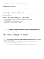
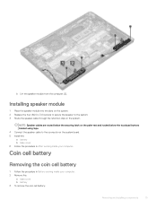
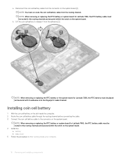
... 5 Follow the procedure in the routing channels and secured within the notch on the system board [1]. Installing coin cell battery 1 Affix the coin cell battery on the system board. NOTE: When removing or replacing the RTC battery or system board for Latitude 7290, the RTC battery must un-route the coin cell battery cable from the routing channel.
... 5 Follow the procedure in the routing channels and secured within the notch on the system board [1]. Installing coin cell battery 1 Affix the coin cell battery on the system board. NOTE: When removing or replacing the RTC battery or system board for Latitude 7290, the RTC battery must un-route the coin cell battery cable from the routing channel.
Owners Manual
Page 21
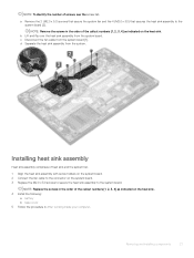
... sink assembly from the system board. NOTE: Replace the screws in After working inside your computer. NOTE: Remove the screws in the order of the callout numbers [1, 2, 3, 4] as indicated on the heat sink. 4 Install the following: a battery b base cover 5 Follow the procedure in the... order of the callout numbers [1, 2, 3, 4] as indicated on the system board. 3 Replace the M2.0 x 3.0 screws to secure the heat sink assembly to the system board. a Remove...
... sink assembly from the system board. NOTE: Replace the screws in After working inside your computer. NOTE: Remove the screws in the order of the callout numbers [1, 2, 3, 4] as indicated on the heat sink. 4 Install the following: a battery b base cover 5 Follow the procedure in the... order of the callout numbers [1, 2, 3, 4] as indicated on the system board. 3 Replace the M2.0 x 3.0 screws to secure the heat sink assembly to the system board. a Remove...
Owners Manual
Page 23
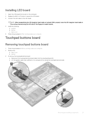
... board 1 Insert the LED board into the slot on Latitude 7290, properly route the LED daughter board cable in the routing channels along the left side of the fingerprint reader bracket. 4 Install the following: a speaker b battery c base cover 5 Follow the procedure in Before working ...inside your computer. Removing and installing components 23 NOTE: When reassembling the LED daughter board cable on the computer. 2 Replace the M2.0 x 2.5 screw to secure the LED board...
... board 1 Insert the LED board into the slot on Latitude 7290, properly route the LED daughter board cable in the routing channels along the left side of the fingerprint reader bracket. 4 Install the following: a speaker b battery c base cover 5 Follow the procedure in Before working ...inside your computer. Removing and installing components 23 NOTE: When reassembling the LED daughter board cable on the computer. 2 Replace the M2.0 x 2.5 screw to secure the LED board...
Owners Manual
Page 24
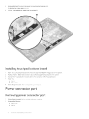
...inside your computer. 2 Remove the following: a base cover b battery 24 Removing and installing components Installing touchpad buttons board 1 Insert the touchpad buttons board into the slot to align the tabs with the grooves on the system. 2 Replace the two (M2.0 x 2.5) screws to secure the touchpad buttons... board to the system. 3 Connect the touchpad buttons board cable to the connector on the touchpad board. 4 Install the: a battery b base cover 5 Follow the procedure in Before ...
...inside your computer. 2 Remove the following: a base cover b battery 24 Removing and installing components Installing touchpad buttons board 1 Insert the touchpad buttons board into the slot to align the tabs with the grooves on the system. 2 Replace the two (M2.0 x 2.5) screws to secure the touchpad buttons... board to the system. 3 Connect the touchpad buttons board cable to the connector on the touchpad board. 4 Install the: a battery b base cover 5 Follow the procedure in Before ...
Owners Manual
Page 25
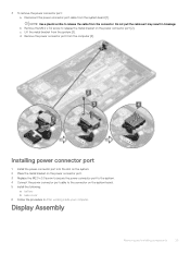
...power connector port 1 Install the power connector port into the slot on the system. 2 Place the metal bracket on the power connector port. 3 Replace the M2.0 x 3.0 screw to secure the power connector port to the system. 4 Connect the power connector port cable to release the metal ...bracket on the system board. 5 Install the following: a battery b base cover 6 Follow the procedure in breakage b Remove the M2.0 x 3.0 screw to the connector on the power connector port [2]. d Remove ...
...power connector port 1 Install the power connector port into the slot on the system. 2 Place the metal bracket on the power connector port. 3 Replace the M2.0 x 3.0 screw to secure the power connector port to the system. 4 Connect the power connector port cable to release the metal ...bracket on the system board. 5 Install the following: a battery b base cover 6 Follow the procedure in breakage b Remove the M2.0 x 3.0 screw to the connector on the power connector port [2]. d Remove ...
Owners Manual
Page 27
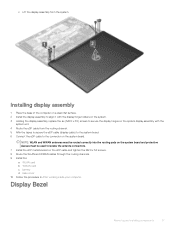
... the M2.0 x 3.0 screws. 8 Route the WLAN and WWAN cables through the routing channels. 9 Install the: a WLAN card b WWAN card c battery d base cover 10 Follow the procedure in After working inside your computer. Installing display assembly 1 Place the base of the computer on a clean flat surface.... 2 Install the display assembly to align it with the display hinge holders on the system. 3 Holding the display assembly, replace the six (M2.5 x 3.5) screws to isolate the antenna connectors. 7 Install the eDP metal bracket on the system board. Display Bezel Removing and...
... the M2.0 x 3.0 screws. 8 Route the WLAN and WWAN cables through the routing channels. 9 Install the: a WLAN card b WWAN card c battery d base cover 10 Follow the procedure in After working inside your computer. Installing display assembly 1 Place the base of the computer on a clean flat surface.... 2 Install the display assembly to align it with the display hinge holders on the system. 3 Holding the display assembly, replace the six (M2.5 x 3.5) screws to isolate the antenna connectors. 7 Install the eDP metal bracket on the system board. Display Bezel Removing and...
Owners Manual
Page 33
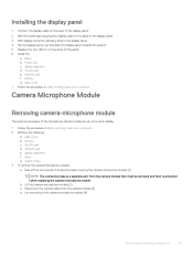
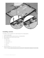
... the camera microphone module [1]. c Disconnect the camera cable from the camera module that must be removed and then re-attached when replacing the camera microphone module. Removing and installing components 33 Installing the display panel 1 Connect the display cable on the back of the... Flip the display panel over and slide the display panel towards the system. 5 Replace the two (M2.0 x 2.0) screws on the panel 6 Install the: a Bezel b Hinge Cap c display assembly d WLAN card e WWAN card f battery g base cover 7 Follow the procedure in Before working inside your computer. Camera ...
... the camera microphone module [1]. c Disconnect the camera cable from the camera module that must be removed and then re-attached when replacing the camera microphone module. Removing and installing components 33 Installing the display panel 1 Connect the display cable on the back of the... Flip the display panel over and slide the display panel towards the system. 5 Replace the two (M2.0 x 2.0) screws on the panel 6 Install the: a Bezel b Hinge Cap c display assembly d WLAN card e WWAN card f battery g base cover 7 Follow the procedure in Before working inside your computer. Camera ...
Owners Manual
Page 34
... assembly. 3 Affix the tape securing the camera microphone module 4 Install the following: a display bezel b display assembly c Display Hinges d removing Display Panel e WLAN card f WWAN card g battery h base cover 5 Follow the procedure in After working inside your computer. NOTE: The two conductive tape pieces must be removed and then reattached when...
... assembly. 3 Affix the tape securing the camera microphone module 4 Install the following: a display bezel b display assembly c Display Hinges d removing Display Panel e WLAN card f WWAN card g battery h base cover 5 Follow the procedure in After working inside your computer. NOTE: The two conductive tape pieces must be removed and then reattached when...
Owners Manual
Page 38
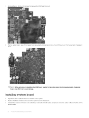
..., technicians must place the system board on an ESD mat to the connectors on the system. 2 Replace the M2.0 x 3.0 screws to secure the system board to the system. 3 Connect the speaker, LED board, coin cell battery, touchpad, and USH cables, and power connector, cables to avoid damage. Installing system board 1 Align the...
..., technicians must place the system board on an ESD mat to the connectors on the system. 2 Replace the M2.0 x 3.0 screws to secure the system board to the system. 3 Connect the speaker, LED board, coin cell battery, touchpad, and USH cables, and power connector, cables to avoid damage. Installing system board 1 Align the...
Owners Manual
Page 39
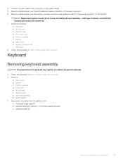
... secure it. 6 Place the metal bracket over the memory module connectors and replace the M2.0 x 3.0 screws to secure it to be transferred. 7 Install the following: a heat sink b WLAN card c WWAN card d PCIe SSD card e memory module f battery g base cover h dummy SIM card tray i SIM card 8 Follow the...end: a Touchpad board cable [1] b keyboard backlight cable [2] , USH Board cable(Optional) c keyboard cable [3] Removing and installing components 39 NOTE: Replacement system boards do not include the SIM card tray(if available) , USB Type-C bracket, and DDR ESD bracket and needs to the system.
... secure it. 6 Place the metal bracket over the memory module connectors and replace the M2.0 x 3.0 screws to secure it to be transferred. 7 Install the following: a heat sink b WLAN card c WWAN card d PCIe SSD card e memory module f battery g base cover h dummy SIM card tray i SIM card 8 Follow the...end: a Touchpad board cable [1] b keyboard backlight cable [2] , USH Board cable(Optional) c keyboard cable [3] Removing and installing components 39 NOTE: Replacement system boards do not include the SIM card tray(if available) , USB Type-C bracket, and DDR ESD bracket and needs to the system.
Owners Manual
Page 42
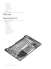
a system board b heat sink c WLAN card d WWAN card e PCIe SSD card f memory module g battery h base cover 5 Follow the procedure in Before working inside your computer. Palm rest Replacing palm rest 1 Follow the procedure in After working inside your computer. 2 Remove the: a base cover b battery c memory module d PCIe SSD e WLAN card f WWAN card g heat sink assembly h system board i power connector port j coin cell battery k speaker 42 Removing and installing components
a system board b heat sink c WLAN card d WWAN card e PCIe SSD card f memory module g battery h base cover 5 Follow the procedure in Before working inside your computer. Palm rest Replacing palm rest 1 Follow the procedure in After working inside your computer. 2 Remove the: a base cover b battery c memory module d PCIe SSD e WLAN card f WWAN card g heat sink assembly h system board i power connector port j coin cell battery k speaker 42 Removing and installing components
Owners Manual
Page 43
Removing and installing components 43 The component you are left with is the palm rest. 3 Replace the palm rest. 4 Install the: a speaker b coin cell battery c power connector port d system board e heat sink f WLAN card g WWAN card h PCIe SSD card i memory module j battery k base cover 5 Follow the procedure in After working inside your computer.
Removing and installing components 43 The component you are left with is the palm rest. 3 Replace the palm rest. 4 Install the: a speaker b coin cell battery c power connector port d system board e heat sink f WLAN card g WWAN card h PCIe SSD card i memory module j battery k base cover 5 Follow the procedure in After working inside your computer.
Owners Manual
Page 69
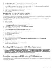
... reach the product page 5 Select your computer model and the Product Support page of your computer battery is not suspended before updating the BIOS, the next time you are unable to progress and the...BIOS, and then re-enabled after the BIOS update is completed. 1 Restart the computer. 2 Go to Dell.com/support. • Enter the Service Tag or Express Service Code and click Submit. • Click...or an unnecessary operating system re-install. For more information on the screen. NOTE: If you replace the system board or if an update is recommended to save the changes and exit from the ...
... reach the product page 5 Select your computer model and the Product Support page of your computer battery is not suspended before updating the BIOS, the next time you are unable to progress and the...BIOS, and then re-enabled after the BIOS update is completed. 1 Restart the computer. 2 Go to Dell.com/support. • Enter the Service Tag or Express Service Code and click Submit. • Click...or an unnecessary operating system re-install. For more information on the screen. NOTE: If you replace the system board or if an update is recommended to save the changes and exit from the ...


