Service Manual
Page 9
Unless otherwise noted, each procedure in your Dell Latitude portable computer. The angle of the display assembly with respect to the bottom case should never be replaced by performing the removal procedure in Figure 1 ... attached peripherals are turned off, and the peripherals are as shown in reverse order. back of computer left side right side front of computer support.dell.com Dell Latitude CPt V-Series/CPx H-Series Service Manual 1
Unless otherwise noted, each procedure in your Dell Latitude portable computer. The angle of the display assembly with respect to the bottom case should never be replaced by performing the removal procedure in Figure 1 ... attached peripherals are turned off, and the peripherals are as shown in reverse order. back of computer left side right side front of computer support.dell.com Dell Latitude CPt V-Series/CPx H-Series Service Manual 1
Service Manual
Page 10
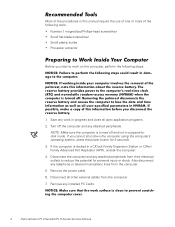
... of the procedures in a C/Dock Family Expansion Station or C/Port Family Advanced Port Replicator (APR), undock the computer. 4. Also disconnect any installed PC Cards. 2 Dell Latitude CPt V-Series/CPx H-Series Service Manual Remove the power cable. 6. Disconnect all open application programs. 2. If you start to reduce the potential for 4 seconds. 3. If the computer is turned...
... of the procedures in a C/Dock Family Expansion Station or C/Port Family Advanced Port Replicator (APR), undock the computer. 4. Also disconnect any installed PC Cards. 2 Dell Latitude CPt V-Series/CPx H-Series Service Manual Remove the power cable. 6. Disconnect all open application programs. 2. If you start to reduce the potential for 4 seconds. 3. If the computer is turned...
Service Manual
Page 11
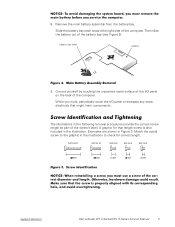
... following removal procedures provide the correct screw length as part of the computer. M2.5x20 M2.5x10 M3.0x5 M2.5x4 M2.0x3 support.dell.com Dell Latitude CPt V-Series/CPx H-Series Service Manual 3 battery bay latch battery 9. Match the actual screw to the graphic in the illustration to dissipate any static electricity that length screw...
... following removal procedures provide the correct screw length as part of the computer. M2.5x20 M2.5x10 M3.0x5 M2.5x4 M2.0x3 support.dell.com Dell Latitude CPt V-Series/CPx H-Series Service Manual 3 battery bay latch battery 9. Match the actual screw to the graphic in the illustration to dissipate any static electricity that length screw...

Service Manual
Page 12
... x 3 (3 each) Palmrest Assembly: M2.5 x 20 (5 each) System Board: M2.5 x 4 (2 each) Microprocessor Shield: 3 captive and 2 removable screws M2 x 3 (2 each) TCA and Exhaust Fan: M2.5 x 4 (2 each) 4 Dell Latitude CPt V-Series/CPx H-Series Service Manual Hard-Disk Drive: M3 x 5 (1 each) Keyboard Assembly: M2.5 x 10 (7 each) Display Assembly: M2.5 x 4 (3 each) Display Assembly Bezel: Rubber Screw Covers (4 each) Plastic Screw...
... x 3 (3 each) Palmrest Assembly: M2.5 x 20 (5 each) System Board: M2.5 x 4 (2 each) Microprocessor Shield: 3 captive and 2 removable screws M2 x 3 (2 each) TCA and Exhaust Fan: M2.5 x 4 (2 each) 4 Dell Latitude CPt V-Series/CPx H-Series Service Manual Hard-Disk Drive: M3 x 5 (1 each) Keyboard Assembly: M2.5 x 10 (7 each) Display Assembly: M2.5 x 4 (3 each) Display Assembly Bezel: Rubber Screw Covers (4 each) Plastic Screw...
Service Manual
Page 13
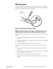
... the cable into the connector. 3. Orient the end of the interface cable with the ZIF connector, and insert the end of the connector. 2. support.dell.com Dell Latitude CPt V-Series/CPx H-Series Service Manual 5 Push gently sideways on the movable part of the connector until it out of the connector. To ensure a firm connection, make sure...
... the cable into the connector. 3. Orient the end of the interface cable with the ZIF connector, and insert the end of the connector. 2. support.dell.com Dell Latitude CPt V-Series/CPx H-Series Service Manual 5 Push gently sideways on the movable part of the connector until it out of the connector. To ensure a firm connection, make sure...
Service Manual
Page 14
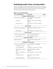
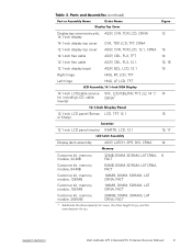
..., NBK, 24X, TSHBA PWA, INTERCONN, CD/DVD, OMAHA ASSY, BTM/BZL, CD, 24X, TSHBA ASSY, HSG, PLSTC, CD/DVD, OMHA LBL, CD, MEDIA BAY, TSHB 6 Dell Latitude CPt V-Series/CPx H-Series Service Manual
..., NBK, 24X, TSHBA PWA, INTERCONN, CD/DVD, OMAHA ASSY, BTM/BZL, CD, 24X, TSHBA ASSY, HSG, PLSTC, CD/DVD, OMHA LBL, CD, MEDIA BAY, TSHB 6 Dell Latitude CPt V-Series/CPx H-Series Service Manual
Service Manual
Page 15
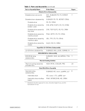
...-disk drive interface PWA, INTERCONN, HD, CRNA board * Substitute the drive capacity for xxxxx, the drive height for yy, and the manufacturer for zzz. support.dell.com Dell Latitude CPt V-Series/CPx H-Series Service Manual 7
...-disk drive interface PWA, INTERCONN, HD, CRNA board * Substitute the drive capacity for xxxxx, the drive height for yy, and the manufacturer for zzz. support.dell.com Dell Latitude CPt V-Series/CPx H-Series Service Manual 7
Service Manual
Page 16
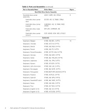
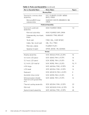
..., D-PTG Keyboard, Swiss KYBD, 88, SWI, D-PTG Keyboard, Thai KYBD, 87, THAI, D-PTG Keyboard, English (U.K.) KYBD, 88, UK, D-PTG Keyboard, English (U.S.) KYBD, 87, DOM, D-PTG 8 Dell Latitude CPt V-Series/CPx H-Series Service Manual
..., D-PTG Keyboard, Swiss KYBD, 88, SWI, D-PTG Keyboard, Thai KYBD, 87, THAI, D-PTG Keyboard, English (U.K.) KYBD, 88, UK, D-PTG Keyboard, English (U.S.) KYBD, 87, DOM, D-PTG 8 Dell Latitude CPt V-Series/CPx H-Series Service Manual
Service Manual
Page 17
..., 256-MB 256MB, DIMM, SDRAM, LAT CRNA, FACT * Substitute the drive capacity for xxxxx, the drive height for yy, and the manufacturer for zzz. support.dell.com Dell Latitude CPt V-Series/CPx H-Series Service Manual 9
..., 256-MB 256MB, DIMM, SDRAM, LAT CRNA, FACT * Substitute the drive capacity for xxxxx, the drive height for yy, and the manufacturer for zzz. support.dell.com Dell Latitude CPt V-Series/CPx H-Series Service Manual 9
Service Manual
Page 18
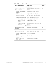
..., ZPS SCR, M2.5X20, PHH, LP, ZPS SCR, M2.5X4, PHH, LP, ZPS 13 14 15 15, 17 13 14 9 6 12 23 19 22 10 Dell Latitude CPt V-Series/CPx H-Series Service Manual
..., ZPS SCR, M2.5X20, PHH, LP, ZPS SCR, M2.5X4, PHH, LP, ZPS 13 14 15 15, 17 13 14 9 6 12 23 19 22 10 Dell Latitude CPt V-Series/CPx H-Series Service Manual
Service Manual
Page 19
... Kit, latch, slider, LTCH, BTN, Module Button Foot, Rubber, Black (4 each) Foot, Rbr, Blk Foot, Rubber, Strike Zone, Black Foot, Rbr, Strike Zone, Blk support.dell.com Dell Latitude CPt V-Series/CPx H-Series Service Manual 11
... Kit, latch, slider, LTCH, BTN, Module Button Foot, Rubber, Black (4 each) Foot, Rbr, Blk Foot, Rubber, Strike Zone, Black Foot, Rbr, Strike Zone, Blk support.dell.com Dell Latitude CPt V-Series/CPx H-Series Service Manual 11

Service Manual
Page 20
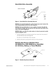
display assembly keyboard palmrest assembly hard-disk drive system board main battery bottom case assembly modular bay device The following subsections provide instructions for removing and replacing field-replaceable parts and assemblies. 12 Dell Latitude CPt V-Series/CPx H-Series Service Manual
display assembly keyboard palmrest assembly hard-disk drive system board main battery bottom case assembly modular bay device The following subsections provide instructions for removing and replacing field-replaceable parts and assemblies. 12 Dell Latitude CPt V-Series/CPx H-Series Service Manual
Service Manual
Page 21
latch lock support.dell.com Dell Latitude CPt V-Series/CPx H-Series Service Manual 13 bottom of the computer. 2. The drive is on the left side of computer 5-mm screw M3.0x5 hard-disk drive door 1. Slide the drive door up and pull the drive out of the hard-disk drive door (see Figure 6). Turn the computer over, and remove the 5-mm screw from the center of the computer.
latch lock support.dell.com Dell Latitude CPt V-Series/CPx H-Series Service Manual 13 bottom of the computer. 2. The drive is on the left side of computer 5-mm screw M3.0x5 hard-disk drive door 1. Slide the drive door up and pull the drive out of the hard-disk drive door (see Figure 6). Turn the computer over, and remove the 5-mm screw from the center of the computer.

Service Manual
Page 22
... turn the computer over. 2. inner tabs (2 per socket) DIMM A DIMM B memory module sockets (2) 1. Release the memory module cover. 1. Remove the memory module cover. 14 Dell Latitude CPt V-Series/CPx H-Series Service Manual Keep holding the latch open while pulling the device out of the modular bay with the other hand (see Figure 7). 1. Close the display...
... turn the computer over. 2. inner tabs (2 per socket) DIMM A DIMM B memory module sockets (2) 1. Release the memory module cover. 1. Remove the memory module cover. 14 Dell Latitude CPt V-Series/CPx H-Series Service Manual Keep holding the latch open while pulling the device out of the modular bay with the other hand (see Figure 7). 1. Close the display...
Service Manual
Page 23
...: 192-MB memory modules are notched so that the memory module is inserted with the double-stacked memory chips facing down until it . support.dell.com Dell Latitude CPt V-Series/CPx H-Series Service Manual 15 To release a memory module from the socket (it in the socket. If you only have one direction. Memory modules are not...
...: 192-MB memory modules are notched so that the memory module is inserted with the double-stacked memory chips facing down until it . support.dell.com Dell Latitude CPt V-Series/CPx H-Series Service Manual 15 To release a memory module from the socket (it in the socket. If you only have one direction. Memory modules are not...

Service Manual
Page 24
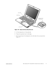
Release the keyboard from the palmrest assembly by inserting a small flat-blade screwdriver under the edge of the keyboard. 16 Dell Latitude CPt V-Series/CPx H-Series Service Manual 10-mm screws (7) M2.5x10 2. Turn the computer right-side up and open the display. 4. Remove the seven 10-mm screws, labeled with a "circle K," that secure the keyboard to the computer (see Figure 10), and lift the right edge of the blank key (see Figure 9). 3.
Release the keyboard from the palmrest assembly by inserting a small flat-blade screwdriver under the edge of the keyboard. 16 Dell Latitude CPt V-Series/CPx H-Series Service Manual 10-mm screws (7) M2.5x10 2. Turn the computer right-side up and open the display. 4. Remove the seven 10-mm screws, labeled with a "circle K," that secure the keyboard to the computer (see Figure 10), and lift the right edge of the blank key (see Figure 9). 3.
Service Manual
Page 25
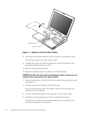
support.dell.com Dell Latitude CPt V-Series/CPx H-Series Service Manual 17 track stick keyboard scalloped edge of the palmrest. 6. Rest the key face of the computer (see Figure 11). Rotate the keyboard over its left side of the keyboard on the left edge. 7. Lift the keyboard out of blank key palmrest 5.
support.dell.com Dell Latitude CPt V-Series/CPx H-Series Service Manual 17 track stick keyboard scalloped edge of the palmrest. 6. Rest the key face of the computer (see Figure 11). Rotate the keyboard over its left side of the keyboard on the left edge. 7. Lift the keyboard out of blank key palmrest 5.
Service Manual
Page 26
... the system board. 4. Ensure that the contact side of the computer with its key face down when you lower the keyboard into the palmrest. 18 Dell Latitude CPt V-Series/CPx H-Series Service Manual
... the system board. 4. Ensure that the contact side of the computer with its key face down when you lower the keyboard into the palmrest. 18 Dell Latitude CPt V-Series/CPx H-Series Service Manual
Service Manual
Page 27
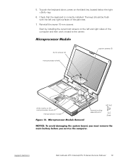
... right sides of the palmrest. 7. 5. To push the keyboard down, press on the microprocessor board (2) microprocessor module M2.0x3 thermal cooling assembly arm support.dell.com Dell Latitude CPt V-Series/CPx H-Series Service Manual 19 Start by installing the outermost screws on the left and right surfaces of the computer and then work inward to the...
... right sides of the palmrest. 7. 5. To push the keyboard down, press on the microprocessor board (2) microprocessor module M2.0x3 thermal cooling assembly arm support.dell.com Dell Latitude CPt V-Series/CPx H-Series Service Manual 19 Start by installing the outermost screws on the left and right surfaces of the computer and then work inward to the...

Service Manual
Page 28
... of the shield to the microprocessor module. 5. Loosen the three captive screws securing the microprocessor shield to secure the microprocessor module and shield. 20 Dell Latitude CPt V-Series/CPx H-Series Service Manual When you reinstall the microprocessor module in the system board, make sure that you align the microprocessor connector on the left side of...
... of the shield to the microprocessor module. 5. Loosen the three captive screws securing the microprocessor shield to secure the microprocessor module and shield. 20 Dell Latitude CPt V-Series/CPx H-Series Service Manual When you reinstall the microprocessor module in the system board, make sure that you align the microprocessor connector on the left side of...


