
Owner's Manual
Page 3
......12 Installing the Base Cover...14 Removing the mSATA SSD Card...14 Installing the mSATA SSD Card...14 Removing the Keyboard Trim...14 Installing the Keyboard Trim...15 Removing the Keyboard...15 Installing the Keyboard...16 Removing the Palmrest...16 Installing the Palmrest...17 Removing the Wi‐Fi Switch Board...17 Installing the...
......12 Installing the Base Cover...14 Removing the mSATA SSD Card...14 Installing the mSATA SSD Card...14 Removing the Keyboard Trim...14 Installing the Keyboard Trim...15 Removing the Keyboard...15 Installing the Keyboard...16 Removing the Palmrest...16 Installing the Palmrest...17 Removing the Wi‐Fi Switch Board...17 Installing the...
Owner's Manual
Page 14
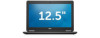
...card and remove the mSATA SSD card from the computer. Tighten the screw to secure the mSATA SSD card to remove the keyboard trim from the computer. 14 Removing the Keyboard Trim 1. Install battery. 4. Remove: a) battery b) SD card c) base cover 3. Follow the procedures in After Working Inside... the screws to secure the base cover to release it from the computer. Installing the mSATA SSD Card 1. Using a plastic scribe, pry the keyboard trim to the computer. 3. Follow the procedures in Before Working Inside Your Computer. 2. Installing the Base Cover 1. Place the base cover to ...
...card and remove the mSATA SSD card from the computer. Tighten the screw to secure the mSATA SSD card to remove the keyboard trim from the computer. 14 Removing the Keyboard Trim 1. Install battery. 4. Remove: a) battery b) SD card c) base cover 3. Follow the procedures in After Working Inside... the screws to secure the base cover to release it from the computer. Installing the mSATA SSD Card 1. Using a plastic scribe, pry the keyboard trim to the computer. 3. Follow the procedures in Before Working Inside Your Computer. 2. Installing the Base Cover 1. Place the base cover to ...

Owner's Manual
Page 15
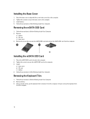
... as shown in the illustration: a) Lift the latch that secure the keyboard cable to the computer. 4. b) Disconnect the keyboard cable the computer [2]. 5. b) Lift the keyboard from the computer [1]. Install battery. 4. Removing the Keyboard 1. Perform the following steps as shown in the illustration: a) Slide the keyboard from the computer [2]. 15 Press along the sides of the...
... as shown in the illustration: a) Lift the latch that secure the keyboard cable to the computer. 4. b) Disconnect the keyboard cable the computer [2]. 5. b) Lift the keyboard from the computer [1]. Install battery. 4. Removing the Keyboard 1. Perform the following steps as shown in the illustration: a) Slide the keyboard from the computer [2]. 15 Press along the sides of the...

Owner's Manual
Page 16
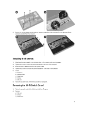
... the cable from the computer. Remove the screws that secures the keyboard cable to the computer. 4. d) Disconnect the touch cable from the slot [4]. 16 Remove: a) SD card b) battery c) base cover d) keyboard trim e) keyboard 3. Removing the Palmrest 1. e) Unroute the cables from the computer [3]. Install: a) keyboard trim b) base cover c) battery 5. b) Lift the latch that secure the...
... the cable from the computer. Remove the screws that secures the keyboard cable to the computer. 4. d) Disconnect the touch cable from the slot [4]. 16 Remove: a) SD card b) battery c) base cover d) keyboard trim e) keyboard 3. Removing the Palmrest 1. e) Unroute the cables from the computer [3]. Install: a) keyboard trim b) base cover c) battery 5. b) Lift the latch that secure the...
Owner's Manual
Page 17
Install: a) keyboard b) keyboard trim c) base cover d) battery e) SD card 6. Tighten the screws to secure the palmrest assembly to the system board. 4. Removing the Wi‐Fi Switch Board 1. ...
Install: a) keyboard b) keyboard trim c) base cover d) battery e) SD card 6. Tighten the screws to secure the palmrest assembly to the system board. 4. Removing the Wi‐Fi Switch Board 1. ...

Owner's Manual
Page 18
Installing the Wi‐Fi Switch Board 1. Follow the procedures in After Working Inside Your Computer. Install: a) palmrest b) keyboard c) keyboard trim d) base cover e) battery f) SD card 5. Follow the procedures in Before Working Inside Your Computer. 2. Removing the Memory Module 1. Insert the ...screw that secures the wi-fi swtich board to the computer. Remove the memory module from the memory module until it pops up. d) keyboard trim e) keyboard f) palmrest 3. Disconnect the wi-fi switch board cable from the system board and remove the screw that secures the wi-fi switch ...
Installing the Wi‐Fi Switch Board 1. Follow the procedures in After Working Inside Your Computer. Install: a) palmrest b) keyboard c) keyboard trim d) base cover e) battery f) SD card 5. Follow the procedures in Before Working Inside Your Computer. 2. Removing the Memory Module 1. Insert the ...screw that secures the wi-fi swtich board to the computer. Remove the memory module from the memory module until it pops up. d) keyboard trim e) keyboard f) palmrest 3. Disconnect the wi-fi switch board cable from the system board and remove the screw that secures the wi-fi switch ...

Owner's Manual
Page 22
...Follow the procedures in After Working Inside Your Computer. 22 b) Disconnect the I/O cables from the system board. Install: a) palmrest b) keyboard c) keyboard trim d) base cover e) battery f) SD card 5. Disconnect from the system board [2]. 5. Follow the procedures in Before Working Inside Your... Computer. 2. Remove: a) SD card b) battery c) base cover d) keyboard trim e) keyboard f) palmrest 3. Installing the Coin-Cell Battery 1. Follow the procedures in its slot. 2. Perform the following steps as shown in...
...Follow the procedures in After Working Inside Your Computer. 22 b) Disconnect the I/O cables from the system board. Install: a) palmrest b) keyboard c) keyboard trim d) base cover e) battery f) SD card 5. Disconnect from the system board [2]. 5. Follow the procedures in Before Working Inside Your... Computer. 2. Remove: a) SD card b) battery c) base cover d) keyboard trim e) keyboard f) palmrest 3. Installing the Coin-Cell Battery 1. Follow the procedures in its slot. 2. Perform the following steps as shown in...
Owner's Manual
Page 23
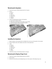
... in Before Working Inside Your Computer. 2. Installing the Speakers 1. d) Remove the speakers from the system board [2]. Install: a) palmrest b) keyboard c) keyboard trim d) base cover e) battery f) SD card 4. Remove: a) SD card b) battery c) base cover d) keyboard trim e) keyboard f) palmrest 3. Removing the Speakers 1. Follow the procedures in the illustration: a) Disconnect the speaker cable [1]. c) Unroute the speaker cable from...
... in Before Working Inside Your Computer. 2. Installing the Speakers 1. d) Remove the speakers from the system board [2]. Install: a) palmrest b) keyboard c) keyboard trim d) base cover e) battery f) SD card 4. Remove: a) SD card b) battery c) base cover d) keyboard trim e) keyboard f) palmrest 3. Removing the Speakers 1. Follow the procedures in the illustration: a) Disconnect the speaker cable [1]. c) Unroute the speaker cable from...

Owner's Manual
Page 24
Remove: a) SD card b) battery c) base cover d) mSATA e) keyboard trim f) keyboard g) palmrest h) display-hinge cover i) display assembly 3. Remove the screws that secure the heatsink to the computer. 2. b) Remove the heatsink from the computer [1]. Place the display-...
Remove: a) SD card b) battery c) base cover d) mSATA e) keyboard trim f) keyboard g) palmrest h) display-hinge cover i) display assembly 3. Remove the screws that secure the heatsink to the computer. 2. b) Remove the heatsink from the computer [1]. Place the display-...

Owner's Manual
Page 25
Install: a) display assembly b) display-hinge cover c) palmrest d) keyboard e) keyboard trim f) mSATA g) base cover h) battery i) SD card 4. b) Unroute the WLAN cables from the wireless solution. Perform the following steps as shown in the illustration: a) Disconnect .... 4. Perform the following steps as shown in the illustration: Disconnect the antenna cables from the slot [2]. Installing the Heatsink 1. Remove: a) battery b) SD card c) base cover d) keyboard e) palmrest 3. c) Remove the screws and pull the antenna cables from the system board [1].
Install: a) display assembly b) display-hinge cover c) palmrest d) keyboard e) keyboard trim f) mSATA g) base cover h) battery i) SD card 4. b) Unroute the WLAN cables from the wireless solution. Perform the following steps as shown in the illustration: a) Disconnect .... 4. Perform the following steps as shown in the illustration: Disconnect the antenna cables from the slot [2]. Installing the Heatsink 1. Remove: a) battery b) SD card c) base cover d) keyboard e) palmrest 3. c) Remove the screws and pull the antenna cables from the system board [1].

Owner's Manual
Page 26
... the computer and lift the display assembly from the computer. Removing the System Fan 1. Follow the procedures in After Working Inside Your Computer. Install: a) palmrest b) keyboard c) base cover d) SD card e) battery 8. Follow the procedures in Before Working Inside Your Computer. 2. Place the display assembly onto the computer. 3. Tighten the screw that...
... the computer and lift the display assembly from the computer. Removing the System Fan 1. Follow the procedures in After Working Inside Your Computer. Install: a) palmrest b) keyboard c) base cover d) SD card e) battery 8. Follow the procedures in Before Working Inside Your Computer. 2. Place the display assembly onto the computer. 3. Tighten the screw that...

Owner's Manual
Page 27
... the screws that secure the system fan to the computer and lift the system fan. Install: a) display-hinge cover b) palmrest c) keyboard d) keyboard trim e) base cover f) SD card g) battery 5. Remove: a) SD card b) battery c) base cover d) mSATA e) keyboard trim f) keyboard g) palmrest h) speaker 27 Follow the procedures in Before Working Inside Your Computer. 2. b) SD card c) base cover...
... the screws that secure the system fan to the computer and lift the system fan. Install: a) display-hinge cover b) palmrest c) keyboard d) keyboard trim e) base cover f) SD card g) battery 5. Remove: a) SD card b) battery c) base cover d) mSATA e) keyboard trim f) keyboard g) palmrest h) speaker 27 Follow the procedures in Before Working Inside Your Computer. 2. b) SD card c) base cover...
Owner's Manual
Page 29
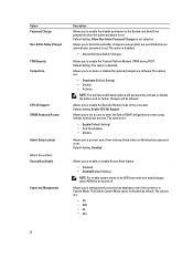
...Insert the power connector in Before Working Inside Your Computer. 2. Install: a) system fan b) palmrest c) keyboard d) base cover 29 Remove: a) SD card b) battery c) base cover d) keyboard e) palmrest f) system fan 3. Disconnect the power-connector cable from the computer. Remove the power connector ... procedures in its slot. 2. b) heat sink c) display assembly d) display-hinge cover e) speaker f) palmrest g) keyboard h) keyboard trim i) mSATA j) base cover k) battery l) SD card 5. Follow the procedures in After Working Inside Your Computer. Removing the Power Connector 1.
...Insert the power connector in Before Working Inside Your Computer. 2. Install: a) system fan b) palmrest c) keyboard d) base cover 29 Remove: a) SD card b) battery c) base cover d) keyboard e) palmrest f) system fan 3. Disconnect the power-connector cable from the computer. Remove the power connector ... procedures in its slot. 2. b) heat sink c) display assembly d) display-hinge cover e) speaker f) palmrest g) keyboard h) keyboard trim i) mSATA j) base cover k) battery l) SD card 5. Follow the procedures in After Working Inside Your Computer. Removing the Power Connector 1.

Owner's Manual
Page 36
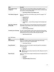
Allows you to choose the operating mode of the keyboard illumination feature. The option is part of the USB PowerShare feature. Allows you to set the mode that will turn off all the options are ...; Level is 25% • Level is 50% • Level is 75% • Level is disabled by default. Option SMART Reporting USB Configuration USB PowerShare Audio Keyboard Illumination Unobtrusive Mode Miscellaneous Devices 36 Description • SATA-0 • SATA-1 • SATA-2 • SATA-3 Default Setting: All drives are : The option is disabled by...
Allows you to choose the operating mode of the keyboard illumination feature. The option is part of the USB PowerShare feature. Allows you to set the mode that will turn off all the options are ...; Level is 25% • Level is 50% • Level is 75% • Level is disabled by default. Option SMART Reporting USB Configuration USB PowerShare Audio Keyboard Illumination Unobtrusive Mode Miscellaneous Devices 36 Description • SATA-0 • SATA-1 • SATA-2 • SATA-3 Default Setting: All drives are : The option is disabled by...
Owner's Manual
Page 38
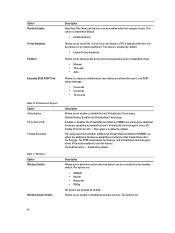
... prevent users from entering Setup when an Administrator password is set . Option Password Change Non-Admin Setup Changes TPM Security Computrace CPU XD Support OROM Keyboard Access Admin Setup Lockout Table 6. Default Setting: The option is disabled by default. The options are : • Deactivate (Default Setting) • Disable • Activate NOTE...
... prevent users from entering Setup when an Administrator password is set . Option Password Change Non-Admin Setup Changes TPM Security Computrace CPU XD Support OROM Keyboard Access Admin Setup Lockout Table 6. Default Setting: The option is disabled by default. The options are : • Deactivate (Default Setting) • Disable • Activate NOTE...
Owner's Manual
Page 41
you to enable this option has no effect, Setup works in the internal keyboard. • Fn Key Only • By Numlock NOTE: When setup is running, this option. If option enables will synchronize emails or social media application that ... messages when certain power adapters are : • Adaptive(Enabled) • Standard Charge • Express Charge • Primary AC Use • Custom Charge - Battery Slice Configuration (Latitude 7240) Allows you to define how to use the battery charge, when AC is disabled by default. • Enable Adapter Warnings Allows you to charge...
you to enable this option has no effect, Setup works in the internal keyboard. • Fn Key Only • By Numlock NOTE: When setup is running, this option. If option enables will synchronize emails or social media application that ... messages when certain power adapters are : • Adaptive(Enabled) • Standard Charge • Express Charge • Primary AC Use • Custom Charge - Battery Slice Configuration (Latitude 7240) Allows you to define how to use the battery charge, when AC is disabled by default. • Enable Adapter Warnings Allows you to charge...
Owner's Manual
Page 42
... virtualization Technology, and Virtualization technology for Direct I /O Trusted Execution Table 11. Description Allows you to match the key feature of PS-2 keyboard with the key feature in an internal keyboard. Trusted Execution - disabled by the wireless switch. The options are enabled by Intel Trusted Execution Technology. Wireless Option Wireless Switch Wireless Device...
... virtualization Technology, and Virtualization technology for Direct I /O Trusted Execution Table 11. Description Allows you to match the key feature of PS-2 keyboard with the key feature in an internal keyboard. Trusted Execution - disabled by the wireless switch. The options are enabled by Intel Trusted Execution Technology. Wireless Option Wireless Switch Wireless Device...
Owner's Manual
Page 48
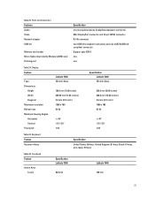
They are usually located either on the top or left side of the keyboard. Solid Blinking Solid The memory modules are installed/detected. Solid Blinking Blinking No memory modules are detected but has encountered an error. Off Blinking Blinking ... and white light Alternately blinking amber light with steady white light Constantly blinking amber light Light off White light on An unauthenticated or unsupported non-Dell AC adapter is enabled. The following table lists how to your laptop. LED Lights Storage LED Power LED Wireless LED Fault Description Blinking Solid Solid...
They are usually located either on the top or left side of the keyboard. Solid Blinking Solid The memory modules are installed/detected. Solid Blinking Blinking No memory modules are detected but has encountered an error. Off Blinking Blinking ... and white light Alternately blinking amber light with steady white light Constantly blinking amber light Light off White light on An unauthenticated or unsupported non-Dell AC adapter is enabled. The following table lists how to your laptop. LED Lights Storage LED Power LED Wireless LED Fault Description Blinking Solid Solid...
Owner's Manual
Page 51
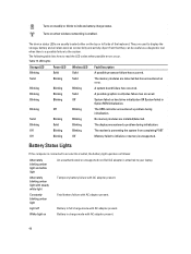
... Support upto SD4.0 one one Table 24. Display Feature Type Dimensions: Height Width Diagonal Maximum resolution Refresh rate Minimum Viewing Angles: Horizontal Vertical Pixel pitch Latitude 7240 HD Anti-Glare 180.0 mm (7.08 inches) 300.90 mm (11.84 inches) 3.6 mm (0.14 inch) 1366 x 768 60 Hz +/-...x 768 60 Hz +/-40° +15°/-30° 1.05 Table 25. Touchpad Feature Active Area: X-axis Specification Latitude 7240 98.8 mm Latitude 7440 100 mm 51 Table 23. Keyboard Feature Number of keys Specification United States: 86 keys, United Kingdom: 87 keys, Brazil: 87 keys, and Japan: 90 ...
... Support upto SD4.0 one one Table 24. Display Feature Type Dimensions: Height Width Diagonal Maximum resolution Refresh rate Minimum Viewing Angles: Horizontal Vertical Pixel pitch Latitude 7240 HD Anti-Glare 180.0 mm (7.08 inches) 300.90 mm (11.84 inches) 3.6 mm (0.14 inch) 1366 x 768 60 Hz +/-...x 768 60 Hz +/-40° +15°/-30° 1.05 Table 25. Touchpad Feature Active Area: X-axis Specification Latitude 7240 98.8 mm Latitude 7440 100 mm 51 Table 23. Keyboard Feature Number of keys Specification United States: 86 keys, United Kingdom: 87 keys, Brazil: 87 keys, and Japan: 90 ...
Setup and Features Information Tech Sheet
Page 1
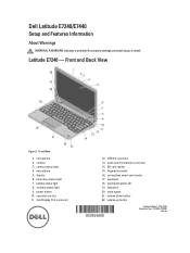
.... keyboard 20. volume up button Regulatory Model: : P22S, P40G Regulatory Type: : P22S001, P40G001 2013- 04 camera 3. wireless status light 9. SD card reader 15. contactless smart-card reader 17. microphone 5. volume down button 22. Latitude E7240 - audio and microphone connector 14. touchpad 18. Front View 1. fingerprint reader 16. mini Display Port connector 12. microphone 2. Dell Latitude E7240...
.... keyboard 20. volume up button Regulatory Model: : P22S, P40G Regulatory Type: : P22S001, P40G001 2013- 04 camera 3. wireless status light 9. SD card reader 15. contactless smart-card reader 17. microphone 5. volume down button 22. Latitude E7240 - audio and microphone connector 14. touchpad 18. Front View 1. fingerprint reader 16. mini Display Port connector 12. microphone 2. Dell Latitude E7240...


